RU2402396C2 - Method of continuous forming of bent or twisted profiles and production line to this end - Google Patents
Method of continuous forming of bent or twisted profiles and production line to this end Download PDFInfo
- Publication number
- RU2402396C2 RU2402396C2 RU2007137019/02A RU2007137019A RU2402396C2 RU 2402396 C2 RU2402396 C2 RU 2402396C2 RU 2007137019/02 A RU2007137019/02 A RU 2007137019/02A RU 2007137019 A RU2007137019 A RU 2007137019A RU 2402396 C2 RU2402396 C2 RU 2402396C2
- Authority
- RU
- Russia
- Prior art keywords
- profile
- rolls
- bending
- tape
- devices
- Prior art date
Links
Images


Classifications
-
- B—PERFORMING OPERATIONS; TRANSPORTING
- B21—MECHANICAL METAL-WORKING WITHOUT ESSENTIALLY REMOVING MATERIAL; PUNCHING METAL
- B21D—WORKING OR PROCESSING OF SHEET METAL OR METAL TUBES, RODS OR PROFILES WITHOUT ESSENTIALLY REMOVING MATERIAL; PUNCHING METAL
- B21D5/00—Bending sheet metal along straight lines, e.g. to form simple curves
- B21D5/14—Bending sheet metal along straight lines, e.g. to form simple curves by passing between rollers
-
- B—PERFORMING OPERATIONS; TRANSPORTING
- B21—MECHANICAL METAL-WORKING WITHOUT ESSENTIALLY REMOVING MATERIAL; PUNCHING METAL
- B21D—WORKING OR PROCESSING OF SHEET METAL OR METAL TUBES, RODS OR PROFILES WITHOUT ESSENTIALLY REMOVING MATERIAL; PUNCHING METAL
- B21D5/00—Bending sheet metal along straight lines, e.g. to form simple curves
- B21D5/06—Bending sheet metal along straight lines, e.g. to form simple curves by drawing procedure making use of dies or forming-rollers, e.g. making profiles
- B21D5/08—Bending sheet metal along straight lines, e.g. to form simple curves by drawing procedure making use of dies or forming-rollers, e.g. making profiles making use of forming-rollers
- B21D5/083—Bending sheet metal along straight lines, e.g. to form simple curves by drawing procedure making use of dies or forming-rollers, e.g. making profiles making use of forming-rollers for obtaining profiles with changing cross-sectional configuration
-
- B—PERFORMING OPERATIONS; TRANSPORTING
- B21—MECHANICAL METAL-WORKING WITHOUT ESSENTIALLY REMOVING MATERIAL; PUNCHING METAL
- B21D—WORKING OR PROCESSING OF SHEET METAL OR METAL TUBES, RODS OR PROFILES WITHOUT ESSENTIALLY REMOVING MATERIAL; PUNCHING METAL
- B21D11/00—Bending not restricted to forms of material mentioned in only one of groups B21D5/00, B21D7/00, B21D9/00; Bending not provided for in groups B21D5/00 - B21D9/00; Twisting
- B21D11/08—Bending by altering the thickness of part of the cross-section of the work
-
- B—PERFORMING OPERATIONS; TRANSPORTING
- B21—MECHANICAL METAL-WORKING WITHOUT ESSENTIALLY REMOVING MATERIAL; PUNCHING METAL
- B21D—WORKING OR PROCESSING OF SHEET METAL OR METAL TUBES, RODS OR PROFILES WITHOUT ESSENTIALLY REMOVING MATERIAL; PUNCHING METAL
- B21D5/00—Bending sheet metal along straight lines, e.g. to form simple curves
- B21D5/06—Bending sheet metal along straight lines, e.g. to form simple curves by drawing procedure making use of dies or forming-rollers, e.g. making profiles
- B21D5/08—Bending sheet metal along straight lines, e.g. to form simple curves by drawing procedure making use of dies or forming-rollers, e.g. making profiles making use of forming-rollers
Abstract
Description
ОБЛАСТЬ ТЕХНИКИFIELD OF TECHNOLOGY
Настоящее изобретение относится к способам формирования из плоской металлической ленты профилей, поперечное сечение которых может изменяться по их длине, и формирования изгиба этих профилей. Изобретение также относится к производственной линии (профилегибочный стан) для непрерывного формирования гнутых профилей, имеющих изменяющуюся форму поперечного сечения по их длине, из плоской металлической ленты, которая разматывается с катушки, причем производственная линия содержит размоточную машину, роликовую правильную машину, штамп для выполнения поперечного выреза в ленте и устройства для отрезания краев ленты, после которых установлен листогибочный роликовый агрегат, состоящий из листогибочных роликовых устройств, причем устройства для отрезания краев ленты и листогибочные роликовые устройства могут независимо перемещаться и направляться в поперечном направлении для непрерывного изменения окончательной формы изготавливаемого профиля.The present invention relates to methods for forming profiles from a flat metal strip, the cross section of which can vary along their length, and forming a bend of these profiles. The invention also relates to a production line (roll forming mill) for the continuous formation of bent profiles having a varying cross-sectional shape along their length, from a flat metal strip that is unwound from a reel, the production line comprising an unwinding machine, a straightening roller machine, a stamp for performing a transverse a cutout in the tape and a device for cutting off the edges of the tape, after which a sheet bending roller assembly consisting of sheet bending roller devices is installed, wherein devices for cutting the edges of the tape and bending roller devices can independently move and be directed in the transverse direction to continuously change the final shape of the manufactured profile.
ПРЕДПОСЫЛКИ СОЗДАНИЯ ИЗОБРЕТЕНИЯBACKGROUND OF THE INVENTION
В публикации WO 02/43886 А1 описывается листогибочная роликовая машина, которая используется для гибки и формирования краев кровельного листа типа "стоячий фальц". Ширина кровельного листа может меняться по его длине, а вертикальные края имеют одинаковую форму по всей длине.Publication WO 02/43886 A1 describes a sheet bending roller machine which is used for bending and forming the edges of a standing seam roof sheet. The width of the roofing sheet can vary along its length, and the vertical edges have the same shape along the entire length.
ЦЕЛЬ ИЗОБРЕТЕНИЯOBJECT OF THE INVENTION
Одной из целей изобретения является обеспечение экономичного производства изогнутых металлических листовых профилей, поперечное сечение которых изменяется по их длине, причем высокая точность выполнения изгиба обеспечивается с низким уровнем внутренних напряжений.One of the objectives of the invention is the provision of economical production of curved metal sheet profiles, the cross section of which varies along their length, and high accuracy of bending is ensured with a low level of internal stresses.
В соответствии с предлагаемым в изобретении способом эта цель достигается путем отрезания края ленты для получения листовой заготовки, сгибом стенок заготовки в нескольких листогибочных роликовых устройствах, которые могут быть независимо друг от друга смещены в поперечном направлении и могут быть повернуты, и прокатом стенок сформированного профиля через пару валков для утончения на одной стороне, так что профиль становится изогнутым, при этом пара валков управляется той же самой программой, которая используется для управления поперечными перемещениями и угловым положением листогибочных роликовых устройств, причем осуществляется это таким образом, что пара валков отслеживает стенки профиля и линия между осями валков всегда удерживается перпендикулярной прокатываемой поверхности.In accordance with the method of the invention, this goal is achieved by cutting off the edges of the tape to obtain a sheet blank, by bending the walls of the blank in several bending roller devices that can be independently displaced in the transverse direction and can be rotated, and by rolling the walls of the formed profile through a pair of rolls for thinning on one side, so that the profile becomes curved, while the pair of rolls is controlled by the same program that is used to control by finite displacements and the angular position of the bending roller devices, this being done in such a way that a pair of rolls tracks the profile walls and the line between the roll axes is always kept perpendicular to the rolled surface.
Предлагаемый в изобретении профилегибочный стан содержит после листогибочного роликового агрегата секцию формирования изгиба профиля, содержащую пару валков, которыми можно управлять так, чтобы они отслеживали стенки профиля и прокатывали части этих стенок для их утончения таким образом, чтобы профиль становился изогнутым или скрученным в процессе его формирования, причем пары валков поддерживаются держателями, которые могут поворачиваться для обеспечения поворота пар валков таким образом, чтобы линия между осями валков в одной паре всегда удерживалась перпендикулярной прокатываемой стенке.The roll-forming mill according to the invention comprises, after the sheet-bending roller assembly, a section for forming a profile bend containing a pair of rolls that can be controlled so that they track the walls of the profile and roll parts of these walls to thin them so that the profile becomes curved or twisted during its formation moreover, the pairs of rolls are supported by holders that can be rotated to ensure rotation of the pairs of rolls so that the line between the axes of the rolls in one pair Always hold the rolled perpendicular to the wall.
Объем изобретения определяется прилагаемой формулой.The scope of the invention is determined by the attached claims.
Ниже приводится краткое описание чертежей, иллюстрирующих пример оборудования, на котором может быть осуществлен предлагаемый в изобретении способ.The following is a brief description of the drawings illustrating an example of equipment on which the inventive method can be implemented.
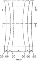
Фигура 1 - схематический вид сбоку предлагаемой в изобретении производственной линии.Figure 1 is a schematic side view of a production line of the invention.
Фигура 2 - вид сверху производственной линии фигуры 1.Figure 2 is a top view of the production line of figure 1.
Фигура 3 - увеличенный вид сечения по линии 3-3 фигуры 2, на котором схематически показан перфорирующий штамп.Figure 3 is an enlarged sectional view along the line 3-3 of figure 2, which schematically shows a perforating stamp.
Фигура 4 - увеличенный вид сечения по линии 4-4 фигуры 2, на котором схематически показано первое устройство для формирования изгиба профиля.Figure 4 is an enlarged sectional view taken along line 4-4 of Figure 2, which schematically shows a first device for forming a profile bend.
Фигура 5 - увеличенный вид сечения по линии 5-5 фигуры 2, на котором схематически показано второе устройство для формирования изгиба профиля.Figure 5 is an enlarged sectional view taken along line 5-5 of Figure 2, which schematically shows a second device for forming a profile bend.
Фигуры 6 и 7 - виды поперечного сечения профиля, сформированного оборудованием, изображенным на предыдущих фигурах, на которых изображенные поперечные сечения соответствуют линиям 6-6 и 7-7 фигуры 8.Figures 6 and 7 are cross-sectional views of a profile formed by the equipment depicted in the previous figures, in which the depicted cross sections correspond to lines 6-6 and 7-7 of figure 8.
Фигура 8 - вид заготовки ленты для формирования профиля, сечения которого показаны на фигурах 6 и 7.Figure 8 is a view of the tape blank for forming a profile, sections of which are shown in figures 6 and 7.
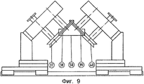
Фигура 9 - иллюстрация конечной стадии гибки на производственной линии для формирования С-образного профиля.Figure 9 is an illustration of the final stage of bending on the production line to form a C-shaped profile.
Фигура 10 - вид пробитой полосы с отрезанными краями перед осуществлением гибки для формирования заданного профиля.Figure 10 is a view of a punched strip with cut edges before bending to form a given profile.
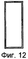
Фигуры 11 и 12 - виды сечений профиля перед трубоформовочным агрегатом и после него (в соответствии с линиями 11-11 и 12-12 фигур 13 и 2).Figures 11 and 12 are views of profile sections in front of and after the pipe forming unit (in accordance with lines 11-11 and 12-12 of figures 13 and 2).
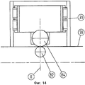
Фигура 13 - увеличенный схематический вид сверху трубоформовочного агрегата.Figure 13 is an enlarged schematic top view of a pipe forming unit.
Фигура 14 - схематический вид сверху части фигуры 4 в процессе проката плоской стенки профиля.Figure 14 is a schematic top view of a portion of Figure 4 during the rolling of a flat profile wall.
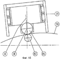
Фигура 15 - вид, соответствующий виду фигуры 14, но для случая формирования криволинейной стенки профиля.Figure 15 is a view corresponding to the view of figure 14, but for the case of the formation of a curved wall of the profile.
ОПИСАНИЕ ПРЕДПОЧТИТЕЛЬНЫХ ВАРИАНТОВ ОСУЩЕСТВЛЕНИЯ ИЗОБРЕТЕНИЯDESCRIPTION OF THE PREFERRED EMBODIMENTS OF THE INVENTION
На фигурах 1 и 2 приведены схематические виды профилегибочного стана, в состав которого входят: размоточная машина 1 для размотки металлической ленты 10 с катушки 9, роликовая правильная машина 12 для правки (выравнивания) металлической ленты 10, штамп 13 первичной обработки, устройства 14, 15 для обрезания краев ленты 10, измельчитель 16 для измельчения отрезанных краев ленты, четыре листогибочных роликовых устройства 17-20 и 21-24 с каждой стороны профиля, агрегат 25 формирования изгиба сформированного профиля, содержащий два устройства 26, 27 формирования изгиба, трубоформовочный агрегат 28 для закрытия сформированного профиля, сварочная установка 29 для сваривания шва закрытого профиля, оконечное отрезное устройство 30 для отрезания готового профиля.Figures 1 and 2 show schematic views of a roll forming mill, which includes: an unwinding machine 1 for unwinding a
На фигуре 3 приведен вид перфорирующего штампа 13 с угловым резцом 31, который начинает просечку в центре ленты, и длина хода определяет длину выполненного выреза.The figure 3 shows a view of a
Устройства 14, 15 для обрезания краев ленты могут независимо друг от друга перемещаться вбок, то есть поперек направления движения ленты. Листогибочные роликовые устройства 17-24 имеют одинаковую конструкцию, и они могут смещаться независимо друг от друга. В их состав входит опорная конструкция, которая, как показано на листогибочном модуле 17, поддерживает две пары валиков 35, 36, работающих в тандеме, и эти ролики могут смещаться в поперечном направлении и поворачиваться вокруг вертикальной оси. Фигура 9 иллюстрирует заключительную стадию формирования профиля с каждой стороны ленты для получения С-образного профиля 50 с помощью двух пар формирующих валиков 37, 38 и 39, 40.The
На фигурах 6 и 7 представлены виды двух поперечных сечений готового С-образного профиля 50, причем сечения асимметричны и изменяются по длине профиля. Края профиля обозначены ссылочными номерами 51, 52, а его углы обозначены ссылочными номерами 53-56. Часть ленты до ее сгибания в заданный профиль показана на фигуре 8. Части ленты, которые после формирования профиля становятся его углами, показаны пунктирными линиями на фигуре 8 до формирования профиля, сечения которого показаны на фигурах 6 и 7. С-образный профиль состоит из центральной стенки 76 между углами 54, 55, двух боковых стенок 77, 78 между углами 53, 54 и 55, 56 и двух полок 79, 80, которые расположены между углами 53, 56 и краями 51, 52 и направлены внутрь.In figures 6 and 7 presents views of two cross sections of the finished C-
Ниже приводится описание изготовления С-образного профиля с изменяющимся поперечным сечением.The following is a description of the manufacture of a C-shaped profile with a varying cross section.
Роликовая правильная машина 12 выравнивает ленту, размотанную с катушки 9, и подает ленту вперед по направлению профилегибочного стана. Подача приостанавливается, когда часть ленты, которая должна быть концом отрезка профиля (готового изделия), достигает перфорационного штампа 13, и в ней вырубается поперечное отверстие. Если задний конец одного отрезка профиля и передний конец следующего отрезка имеют разную ширину, например передний конец шире, чем задний конец предыдущего отрезка профиля, как показано на фигуре 10, то сначала выполняется вырез 60 для заднего конца и затем выполняется вырез 61 для переднего конца после того, как лента подается вперед на некоторое расстояние. Часть ленты, находящаяся между вырезами, уходит в отходы, когда два соседних отрезка профиля отрезаются, как это описано ниже. На фигуре 10 показана лента, как она выглядит после формирования вырезов и отрезания краев. Длины вырезов выбираются таким образом, чтобы углы 53, 56 готового профиля удалялись при выполнении вырезов и оставались только плоские части между углами 53, 56 и концами 51, 52. Вырезы имеют ширину, достаточную для того, чтобы позже можно было отрезать готовый профиль с помощью инструментов, которые вводятся через вырезы снизу.The
Края ленты могут отрезаться после выполнения вырезов, как это делается в описываемом варианте осуществления изобретения, или перед выполнением вырезов. Если полки готового профиля должны быть отогнуты наружу, то необязательно отрезать края перед формированием профиля. В этом случае можно отрезать края после формирования профиля, но перед формированием продольного изгиба. Однако отрезание краев перед формированием профиля, как это делается в описываемом варианте осуществления изобретения, является предпочтительным, в частности, потому что описываемый профилегибочный стан может быть универсальным.The edges of the tape can be cut after making cuts, as is done in the described embodiment of the invention, or before making cuts. If the shelves of the finished profile must be bent outward, then it is not necessary to cut off the edges before forming the profile. In this case, it is possible to cut off the edges after forming a profile, but before forming a longitudinal bend. However, cutting off the edges before forming the profile, as is done in the described embodiment of the invention, is preferred, in particular, because the described roll forming mill can be universal.
Управление работой двух листогибочных устройств 17, 18 и 21, 22 с каждой стороны ленты осуществляется таким образом, что их формирующие ролики следуют по линиям 53, 56, показанным на фигуре 8, то есть они обеспечивают формирование углов 53, 56 (см. фигуры 6, 7). Формирование этих углов осуществляется в две стадии с помощью пар формирующих роликов, работающих в тандеме в каждом листогибочном устройстве, и поэтому каждая пара роликов не следует точно по линии, указанной на фигуре 8. Однако кривизна линий невелика, и поэтому ошибка будет настолько мала, что не будет иметь практического значения. Также во многих случаях могут обеспечиваться три стадии формирования углов каждым из листогибочных устройств 17-24. Также при необходимости можно использовать несколько листогибочных устройств, установленных одно за другим, так что можно формировать каждый угол за несколько стадий и можно формировать более четырех углов, используемых в описываемом варианте осуществления изобретения. Термин "угол" используется для обозначения не только заостренных углов, как показано на фигурах, но также и углов с закруглением. Также не является обязательным формирование профиля симметрично с двух сторон ленты, как показано на прилагаемых фигурах.The operation of the two
При прохождении некоторой точки ленты через листогибочные устройства 18 и 22 углы 53 и 56 полностью формируются, и после этого начинается формирование углов 54, 55. После того как лента пройдет последнее листогибочное устройство, заданный профиль окончательно сформирован, и в случае когда профиль является незамкнутым С-образным профилем, он проходит через секцию 25 формирования изгиба, трубоформовочный агрегат 28 и сварочную установку 29 без дополнительной обработки или формирования. Когда первый вырез 60 достигает оконечного отрезного устройства 30, подача ленты приостанавливается и режущий инструмент входит в вырез и полностью разрезает профиль. Затем лента снова подается вперед и останавливается, когда вырез 61 достигает оконечного отрезного устройства 30. Профиль разрезается в этом месте, и промежуточная секция профиля уходит в отходы. В принципе, в качестве альтернативного варианта можно полностью отрезать ленту до стадии формирования профиля, однако вариант с формированием профиля неразрезанной ленты является предпочтительным. Также, естественно, можно формировать другие профили кроме С-образного профиля, формируемого в описываемом варианте осуществления изобретения, например корытные гнутые профили. При использовании большего количества листогибочных устройств можно формировать профили, имеющие большее число углов, чем показано на прилагаемых фигурах. Для каждого вида профиля можно определить количество листогибочных роликовых устройств, которые должны использоваться для формирования каждого угла, поскольку листогибочные устройства могут управляться независимо друг от друга.When some point of the tape passes through the
Когда должен формироваться замкнутый С-образный профиль, то он не может быть полностью сформирован роликами, поскольку формирующие ролики необходимо вводить внутрь профиля, как показано на фигуре 9. Поэтому формирование с помощью роликов заканчивается формированием профиля, показанного на фигуре 11, и затем в роликовом листогибочном устройстве 28 с использованием одной или нескольких стадий осуществляется обжим профиля вертикальными роликами 65-68, причем нижняя часть профиля опирается при этом на горизонтальные ролики 69, 70, как показано на фигурах 1 и 2 и в увеличенном виде на фигуре 13. После этого профиль приобретает замкнутую форму, показанную на фигуре 12, и затем непосредственно выполняется сварка шва сварочной установкой 29, которая размещается сразу же за листогибочным устройством 28 так, чтобы профиль не мог раскрыться под действием сил упругости.When a closed C-shaped profile is to be formed, it cannot be completely formed by the rollers, since the forming rollers must be introduced into the profile, as shown in figure 9. Therefore, the formation using the rollers ends with the formation of the profile shown in figure 11, and then in the roller the
На фигурах 4 и 5 показаны два устройства 26, 27 формирования изгиба, которые используются, когда необходимо придать профилю изгиб или скрутить его. На профиле 50 указаны те же ссылочные номера, что и на фигуре 6, хотя не все номера присутствуют на фигуре 4.In figures 4 and 5 shows two
Устройство 26 формирования изгиба, показанное на фигуре 4, описывается ниже более подробно. Оно состоит из двух независимых рам 26А и 26В, каждая из которых поддерживает пары валков 82, 84 и 83, 85 соответственно. Каждая пара валков содержит опорные валки 82, 83 внутри профиля 50, и положение этих опорных валков может регулироваться так, чтобы они соприкасались с верхними частями боковых стенок профиля 50, который установлен вертикально. Валки 84, 85 соприкасаются с внешними поверхностями боковых стенок. Таким образом, устройство 26 формирования изгиба содержит одну пару валков 82, 84 с одной стороны профиля 50 и еще одну пару валков 83, 85 с другой стороны профиля. Эти пары валков установлены таким образом, что они могут смещаться независимо друг от друга. Рамы 26А и 26В поддерживаются опорными рамами 31, 32, которые могут поворачиваться на некоторый угол вокруг опорных осей 33, 34, поддерживаемых рамой устройства. Рамы 26А и 26В могут смещаться по вертикали вдоль направляющих 86, 87 в опорных рамах 31, 32. Опорные валки поддерживаются устройствами 90, 91, которые могут скользить в боковом направлении вдоль направляющих 92А и 92В, а ролики 84, 85 поддерживаются устройствами 93, 94, которые могут скользить по направляющим 95А и 95В. Положение опорных валков и валков 82-85 может быть подогнано под форму профиля, поскольку углы, под которыми они установлены, могут регулироваться в некотором ограниченном секторе внутри соответствующих устройств 90, 91, 93, 94 вдоль поверхности круга, показанного пунктирными линиями 96, и их положение может быть отрегулировано таким образом, что зазор между ними должен становиться меньше для обеспечения непрерывного утончения прокатываемого металла в одном направлении. Различные силовые приводы, осуществляющие регулировку и приложение сил, на чертеже не показаны. Для этого могут использоваться, например, гидравлические устройства.The
Профиль будет иметь изгиб по направлению вниз, если валки прижимаются с большой силой и с некоторым наклоном по отношению к боковым стенкам профиля для их постепенного утончения в направлении вверх. Валки дополняются поддерживающими и направляющими роликами, размещенными за валками для придания профилю точной формы по всем трем измерениям. На фигурах эти поддерживающие и направляющие ролики не показаны.The profile will have a downward bend if the rolls are pressed with great force and with some inclination with respect to the side walls of the profile for their gradual thinning in the upward direction. The rollers are complemented by support and guide rollers located behind the rollers to give the profile an exact shape in all three dimensions. In the figures, these support and guide rollers are not shown.
Устройство 27, показанное на фигуре 5, имеет такую же конструкцию, что и устройство 26, описанное выше со ссылками на фигуру 4. Поэтому подробное описание устройства, показанного на фигуре 5, не приводится. Эквивалентные части и элементы на фигуре 5 имеют такие же ссылочные номера, что и на фигуре 4. Валки 84, 85 предназначены для проката боковых стенок профиля для их утончения по сравнению с центральной стенкой профиля 50, так что профиль изгибается по направлению вверх.The
Для того чтобы придать профилю изгиб в боковом направлении, используются валки обоих устройств на одной и той же стороне, так что вся боковая стенка с одной стороны профиля утончается и профиль изгибается в противоположном направлении. Для того чтобы скрутить профиль, используется валок устройства 26 на одной боковой стенке профиля, а валок устройства 27 используется на второй боковой стороне профиля.In order to give the profile a bend in the lateral direction, the rolls of both devices are used on the same side, so that the entire side wall on one side of the profile is thinned and the profile bends in the opposite direction. In order to twist the profile, the roll of the
На фигурах 14 и 15 показаны виды сверху одной боковой стороны 78 профиля 50 (см. фигуры 6 и 7) в процессе проката с использованием одной из пар изгибающих валков 82, 84. Стенка 78 на фигуре 14 плоская, в то время как на фигуре 15 она имеет изгиб. Опорная рама 31, то есть держатель пары валков 82, 84, может поворачиваться вокруг своей опорной оси 33, то есть вокруг оси III, которая, как показано, проходит через центр валка 84, так что линия II между осями пары валков 82, 84 всегда будет перпендикулярна стенке 78. Поворот опорной рамы 31 соответствует повороту листогибочных роликовых устройств.Figures 14 and 15 show top views of one
Таким образом, можно изгибать профиль в произвольно выбранном направлении путем управления силой, приложенной к валкам 84, 85, а также можно скручивать профиль в заданном направлении. Кроме того, можно управлять всеми четырьмя валками одновременно, так что профиль может одновременно иметь кривизну и быть скрученным.Thus, it is possible to bend the profile in an arbitrarily selected direction by controlling the force exerted on the
Также необходимо обеспечивать возможность смещения устройств, которые находятся после устройства формирования изгиба, а именно трубоформовочного агрегата 28, сварочной установки 29 и оконечной отрезной установки 30 как в вертикальном, так и в горизонтальном направлениях, и необходимо обеспечивать возможность поворота этих устройств, если они должны использоваться для изогнутых или скрученных профилей.It is also necessary to provide the possibility of displacement of devices that are located after the device for forming a bend, namely, the
Не все устройства, используемые на профилегибочном стане для скручивания, смещения и т.п., показаны на чертежах. Все эти устройства управляются программируемой компьютерной системой, так что они работают согласованно для получения нужного результата. Листогибочные устройства 17, 18 или 21, 22 с одной стороны и ролики 82, 84 или 83, 85 для формирования кривизны, находящиеся с этой же стороны, управляются одной и той же компьютерной программой, так что листогибочные устройства, предназначенные для сгиба стенок профиля 50 и формирования углов 54, 58, и пары валков, предназначенные для проката этих стенок, будут перемещаться согласованно как в отношении их смещения в боковом направлении, так и в отношении их углового перемещения в процессе изготовления профиля 50 и во время придания ему изгиба. Также желательно, чтобы управление движением частей 26А и 26В устройства формирования изгиба по направляющим 86, 87 осуществлялось компьютером. Это движение не является обязательным, если стенки профиля имеют постоянную высоту.Not all devices used on a roll forming mill for twisting, displacing, etc., are shown in the drawings. All of these devices are controlled by a programmable computer system, so that they work in concert to obtain the desired result. The
Вышеописанный профилегибочный стан является техническим комплексом, обеспечивающим формирование профиля и его изгиб, и такое решение часто является предпочтительным. Однако можно использовать отдельные машины для формирования профиля и для изгиба, и в этом случае одна и та же программа используется для управления листогибочными устройствами для осуществления гибки стенок и для управления валками формирования изгиба для того, чтобы они отслеживали стенки вышеописанным образом.The above bending mill is a technical complex that provides the formation of the profile and its bending, and such a solution is often preferred. However, separate machines for forming the profile and for bending can be used, in which case the same program is used to control the bending devices for bending the walls and to control the bending rolls so that they track the walls in the manner described above.
Claims (7)
Applications Claiming Priority (2)
| Application Number | Priority Date | Filing Date | Title |
|---|---|---|---|
| SE0500954A SE0500954L (en) | 2005-04-28 | 2005-04-28 | Production line and way of forming profiles |
| SE0500954-3 | 2005-04-28 |
Publications (2)
| Publication Number | Publication Date |
|---|---|
| RU2007137019A RU2007137019A (en) | 2009-06-10 |
| RU2402396C2 true RU2402396C2 (en) | 2010-10-27 |
Family
ID=35788952
Family Applications (1)
| Application Number | Title | Priority Date | Filing Date |
|---|---|---|---|
| RU2007137019/02A RU2402396C2 (en) | 2005-04-28 | 2006-04-24 | Method of continuous forming of bent or twisted profiles and production line to this end |
Country Status (16)
| Country | Link |
|---|---|
| US (1) | US8650923B2 (en) |
| EP (1) | EP1877205B1 (en) |
| JP (1) | JP5033120B2 (en) |
| KR (1) | KR101470884B1 (en) |
| CN (1) | CN101166586B (en) |
| BR (1) | BRPI0610981B1 (en) |
| CA (1) | CA2604626C (en) |
| CY (1) | CY1115881T1 (en) |
| DK (1) | DK1877205T3 (en) |
| ES (1) | ES2526615T3 (en) |
| PL (1) | PL1877205T3 (en) |
| PT (1) | PT1877205E (en) |
| RU (1) | RU2402396C2 (en) |
| SE (1) | SE0500954L (en) |
| SI (1) | SI1877205T1 (en) |
| WO (1) | WO2006115447A1 (en) |
Cited By (2)
| Publication number | Priority date | Publication date | Assignee | Title |
|---|---|---|---|---|
| RU2610375C2 (en) * | 2011-07-13 | 2017-02-09 | Хильти Акциенгезельшафт | Method for producing profile from sheet metal strip |
| RU209754U1 (en) * | 2021-08-18 | 2022-03-22 | Игорь Сергеевич Виноградов | Device for metal sheet profiling and straightening |
Families Citing this family (28)
| Publication number | Priority date | Publication date | Assignee | Title |
|---|---|---|---|---|
| CN101462133B (en) * | 2007-12-17 | 2011-06-29 | 上海中集冷藏箱有限公司 | Method and device for processing aluminium section bar board for refrigerating box |
| KR100867236B1 (en) * | 2007-12-21 | 2008-11-10 | 주원철 | Manufacturing apparatus for section shape steel |
| US8984923B2 (en) * | 2010-01-18 | 2015-03-24 | Metalforming, Inc. | Programmable roll former and angle cutter |
| KR101047074B1 (en) * | 2008-07-25 | 2011-07-06 | 장쌍권 | Embossing molding automatic control device |
| DE202008013876U1 (en) * | 2008-10-20 | 2010-03-18 | Walter Möck GmbH | Apparatus for roll forming sheet metal |
| DE202010001152U1 (en) * | 2010-01-15 | 2011-05-26 | Weber, Axel, 72138 | Device for roll forming profiling and crowning of metal strip sections |
| US20120103957A1 (en) * | 2010-11-01 | 2012-05-03 | Powers Iii John | Metal stud fabricator |
| CN101985140B (en) * | 2010-11-05 | 2012-07-18 | 安阳艾尔旺新能源环境有限公司 | Bending forming method and device for circular edge section |
| CN102271486A (en) * | 2011-07-21 | 2011-12-07 | 尹钟哲 | Radiating structure, and application, manufacturing device and manufacturing method thereof |
| DE102011121512A1 (en) * | 2011-12-16 | 2013-06-20 | Sms Meer Gmbh | angle rolls |
| JP5876723B2 (en) * | 2011-12-27 | 2016-03-02 | 日鐵住金建材株式会社 | Roll forming method |
| DE202012003769U1 (en) * | 2012-04-16 | 2013-01-22 | Axel Weber | Rollformvorrichtung for roll forming a roll of material strip |
| CN103510799A (en) * | 2012-06-20 | 2014-01-15 | 深圳天派门窗科技有限公司 | Aluminum alloy and wood plastic composite section material and corresponding manufacturing method and device |
| CN102814661A (en) * | 2012-08-08 | 2012-12-12 | 苏州海仑士科技有限公司 | Automatic production line for intelligent sheet metal |
| KR101472671B1 (en) * | 2013-04-24 | 2014-12-15 | 김형건 | Pressurizing roller frame of the door sheet forming device |
| KR200471873Y1 (en) * | 2013-10-17 | 2014-03-19 | 임흥순 | Apparatus for Manufacturing Roller Track |
| DE102014115426B4 (en) * | 2014-10-23 | 2018-07-26 | Thyssenkrupp Ag | Apparatus and method for continuously advancing metal bands to a profile of longitudinally variable cross-section |
| CN104858297B (en) * | 2015-04-07 | 2017-11-10 | 苏州金童机械制造股份有限公司 | Multi-functional plate flexible product line |
| CN106347964A (en) * | 2016-10-31 | 2017-01-25 | 上海前孟计算机科技有限公司 | Automatic sorting and conveying device used for suppository unit type independent forming mould |
| SE1700021A1 (en) | 2017-02-07 | 2018-05-29 | Ingvest Ab | Method and apparatus for rolling flat products of varying width |
| CA3054697C (en) | 2018-09-21 | 2023-09-19 | The Bradbury Company, Inc. | Machines to roll-form variable component geometries |
| WO2020078753A1 (en) * | 2018-10-15 | 2020-04-23 | Metal Envelope Gmbh | Device and method for the flexible roll forming of a semifinished product |
| EP3643419B1 (en) * | 2018-10-22 | 2021-05-26 | PROFILMETALL Engineering GmbH | Profiling installation with profiling installation module |
| CN110026736A (en) * | 2019-03-22 | 2019-07-19 | 厦门美舜机械设备有限公司 | A kind of forming method sheet material and device |
| CN113814317B (en) * | 2020-06-18 | 2023-12-12 | 宝山钢铁股份有限公司 | Plate rolling process and device thereof |
| KR102412105B1 (en) * | 2020-09-17 | 2022-06-22 | 주식회사 포스코 | Apparatus for roll stamping |
| DE102022101741A1 (en) | 2022-01-26 | 2023-07-27 | Schaeffler Technologies AG & Co. KG | punching device |
| CN116351929B (en) * | 2023-05-29 | 2023-08-01 | 四川华体照明科技股份有限公司 | Board bending device and bending method for manufacturing lamp post |
Family Cites Families (12)
| Publication number | Priority date | Publication date | Assignee | Title |
|---|---|---|---|---|
| JPS6032532B2 (en) * | 1978-03-08 | 1985-07-29 | 日立金属株式会社 | Cold roll forming method |
| US4418558A (en) * | 1981-07-27 | 1983-12-06 | Bantam Systems, Inc. | Method of manufacture of ventilated sheet metal floor members |
| DE3738566A1 (en) * | 1987-04-01 | 1988-10-13 | Spaeth Gmbh & Co Kg Stahlbau B | METHOD AND DEVICE FOR BENDING A SHEET |
| JPH04127924A (en) | 1990-09-17 | 1992-04-28 | Hitachi Ltd | Method for roll forming |
| JPH0790285B2 (en) | 1993-05-20 | 1995-10-04 | 中部エンジニアリング株式会社 | Metal plate forming equipment |
| JP2707217B2 (en) | 1994-09-05 | 1998-01-28 | 元旦ビューティ工業株式会社 | Forming machine and forming method for exterior thatch material |
| AU734061B2 (en) * | 1997-03-26 | 2001-05-31 | Bluescope Steel Limited | Tapering of sheet material |
| JPH1147836A (en) | 1997-07-28 | 1999-02-23 | Toyota Motor Corp | Method for roll bending and device therefor |
| US6820451B2 (en) * | 2000-01-14 | 2004-11-23 | Magna International Inc. | Sweep forming assembly and method |
| SE521076C2 (en) * | 2000-11-29 | 2003-09-30 | Ortic Ab | Roll forming machine with removable forming stations |
| SE521864C2 (en) | 2001-09-27 | 2003-12-16 | Ortic Ab | Curvature and ways of curving roof sheet |
| SE528078C2 (en) | 2004-02-27 | 2006-08-29 | Ortic Ab | Ways to shape profiles in a production line |
-
2005
- 2005-04-28 SE SE0500954A patent/SE0500954L/en unknown
-
2006
- 2006-04-24 PT PT67333120T patent/PT1877205E/en unknown
- 2006-04-24 US US11/918,705 patent/US8650923B2/en not_active Expired - Fee Related
- 2006-04-24 CA CA2604626A patent/CA2604626C/en not_active Expired - Fee Related
- 2006-04-24 ES ES06733312.0T patent/ES2526615T3/en active Active
- 2006-04-24 RU RU2007137019/02A patent/RU2402396C2/en not_active IP Right Cessation
- 2006-04-24 BR BRPI0610981-0A patent/BRPI0610981B1/en not_active IP Right Cessation
- 2006-04-24 PL PL06733312T patent/PL1877205T3/en unknown
- 2006-04-24 SI SI200631869T patent/SI1877205T1/en unknown
- 2006-04-24 WO PCT/SE2006/000456 patent/WO2006115447A1/en active Application Filing
- 2006-04-24 DK DK06733312.0T patent/DK1877205T3/en active
- 2006-04-24 EP EP06733312.0A patent/EP1877205B1/en active Active
- 2006-04-24 JP JP2008508790A patent/JP5033120B2/en not_active Expired - Fee Related
- 2006-04-24 CN CN200680014147XA patent/CN101166586B/en not_active Expired - Fee Related
-
2007
- 2007-11-16 KR KR1020077026708A patent/KR101470884B1/en not_active IP Right Cessation
-
2014
- 2014-12-29 CY CY20141101086T patent/CY1115881T1/en unknown
Cited By (2)
| Publication number | Priority date | Publication date | Assignee | Title |
|---|---|---|---|---|
| RU2610375C2 (en) * | 2011-07-13 | 2017-02-09 | Хильти Акциенгезельшафт | Method for producing profile from sheet metal strip |
| RU209754U1 (en) * | 2021-08-18 | 2022-03-22 | Игорь Сергеевич Виноградов | Device for metal sheet profiling and straightening |
Also Published As
| Publication number | Publication date |
|---|---|
| CY1115881T1 (en) | 2017-04-26 |
| EP1877205A4 (en) | 2013-08-28 |
| KR20080000653A (en) | 2008-01-02 |
| US20090025446A1 (en) | 2009-01-29 |
| PL1877205T3 (en) | 2015-03-31 |
| JP2008539083A (en) | 2008-11-13 |
| KR101470884B1 (en) | 2014-12-09 |
| SE527352C2 (en) | 2006-02-14 |
| PT1877205E (en) | 2015-01-05 |
| SI1877205T1 (en) | 2015-02-27 |
| CA2604626A1 (en) | 2006-11-02 |
| RU2007137019A (en) | 2009-06-10 |
| SE0500954L (en) | 2006-02-14 |
| CN101166586B (en) | 2012-08-08 |
| US8650923B2 (en) | 2014-02-18 |
| WO2006115447A1 (en) | 2006-11-02 |
| CA2604626C (en) | 2013-08-13 |
| DK1877205T3 (en) | 2015-01-12 |
| EP1877205A1 (en) | 2008-01-16 |
| BRPI0610981B1 (en) | 2019-04-24 |
| ES2526615T3 (en) | 2015-01-13 |
| EP1877205B1 (en) | 2014-10-01 |
| BRPI0610981A2 (en) | 2010-08-10 |
| CN101166586A (en) | 2008-04-23 |
| JP5033120B2 (en) | 2012-09-26 |
Similar Documents
| Publication | Publication Date | Title |
|---|---|---|
| RU2402396C2 (en) | Method of continuous forming of bent or twisted profiles and production line to this end | |
| RU2362644C2 (en) | Method for section bar shaping and process line for its realisation | |
| US6678938B2 (en) | System for fabricating muntin bars from sheet material | |
| RU2401710C2 (en) | Profile-iron bending machine and method of sheet shaping | |
| JP2008539083A5 (en) | ||
| CN111037368B (en) | Automatic production line for rolling profiles | |
| CA2550052C (en) | System for fabricating muntin bars from sheet material | |
| KR20210041205A (en) | Construction profile molding method | |
| KR20070021168A (en) | A production line and a method of forming profiles | |
| EP0623403B1 (en) | Method of forming welded pipe and forming stand therefor | |
| AU2008334969A1 (en) | Arching metallic profiles in continuous in-line process | |
| SE528077C2 (en) | Production line process for forming sheet metal profiles, uses individually controllable edge cutting devices and roller forming units to form profile corners | |
| EP0515190A1 (en) | Formation of flat metal strip into channel section |
Legal Events
| Date | Code | Title | Description |
|---|---|---|---|
| PC41 | Official registration of the transfer of exclusive right |
Effective date: 20170414 |
|
| MM4A | The patent is invalid due to non-payment of fees |
Effective date: 20200425 |