RU2397859C2 - Cutting and creasing disk unit and procedure for compressed material cutting and creasing - Google Patents
Cutting and creasing disk unit and procedure for compressed material cutting and creasing Download PDFInfo
- Publication number
- RU2397859C2 RU2397859C2 RU2007135344A RU2007135344A RU2397859C2 RU 2397859 C2 RU2397859 C2 RU 2397859C2 RU 2007135344 A RU2007135344 A RU 2007135344A RU 2007135344 A RU2007135344 A RU 2007135344A RU 2397859 C2 RU2397859 C2 RU 2397859C2
- Authority
- RU
- Russia
- Prior art keywords
- disk
- halves
- scoring
- cutting
- creasing
- Prior art date
Links
Images
Classifications
-
- B—PERFORMING OPERATIONS; TRANSPORTING
- B26—HAND CUTTING TOOLS; CUTTING; SEVERING
- B26D—CUTTING; DETAILS COMMON TO MACHINES FOR PERFORATING, PUNCHING, CUTTING-OUT, STAMPING-OUT OR SEVERING
- B26D1/00—Cutting through work characterised by the nature or movement of the cutting member or particular materials not otherwise provided for; Apparatus or machines therefor; Cutting members therefor
- B26D1/01—Cutting through work characterised by the nature or movement of the cutting member or particular materials not otherwise provided for; Apparatus or machines therefor; Cutting members therefor involving a cutting member which does not travel with the work
- B26D1/12—Cutting through work characterised by the nature or movement of the cutting member or particular materials not otherwise provided for; Apparatus or machines therefor; Cutting members therefor involving a cutting member which does not travel with the work having a cutting member moving about an axis
- B26D1/14—Cutting through work characterised by the nature or movement of the cutting member or particular materials not otherwise provided for; Apparatus or machines therefor; Cutting members therefor involving a cutting member which does not travel with the work having a cutting member moving about an axis with a circular cutting member, e.g. disc cutter
- B26D1/141—Cutting through work characterised by the nature or movement of the cutting member or particular materials not otherwise provided for; Apparatus or machines therefor; Cutting members therefor involving a cutting member which does not travel with the work having a cutting member moving about an axis with a circular cutting member, e.g. disc cutter for thin material, e.g. for sheets, strips or the like
-
- B—PERFORMING OPERATIONS; TRANSPORTING
- B26—HAND CUTTING TOOLS; CUTTING; SEVERING
- B26D—CUTTING; DETAILS COMMON TO MACHINES FOR PERFORATING, PUNCHING, CUTTING-OUT, STAMPING-OUT OR SEVERING
- B26D1/00—Cutting through work characterised by the nature or movement of the cutting member or particular materials not otherwise provided for; Apparatus or machines therefor; Cutting members therefor
- B26D1/01—Cutting through work characterised by the nature or movement of the cutting member or particular materials not otherwise provided for; Apparatus or machines therefor; Cutting members therefor involving a cutting member which does not travel with the work
- B26D1/12—Cutting through work characterised by the nature or movement of the cutting member or particular materials not otherwise provided for; Apparatus or machines therefor; Cutting members therefor involving a cutting member which does not travel with the work having a cutting member moving about an axis
- B26D1/14—Cutting through work characterised by the nature or movement of the cutting member or particular materials not otherwise provided for; Apparatus or machines therefor; Cutting members therefor involving a cutting member which does not travel with the work having a cutting member moving about an axis with a circular cutting member, e.g. disc cutter
- B26D1/22—Cutting through work characterised by the nature or movement of the cutting member or particular materials not otherwise provided for; Apparatus or machines therefor; Cutting members therefor involving a cutting member which does not travel with the work having a cutting member moving about an axis with a circular cutting member, e.g. disc cutter coacting with a movable member, e.g. a roller
- B26D1/225—Cutting through work characterised by the nature or movement of the cutting member or particular materials not otherwise provided for; Apparatus or machines therefor; Cutting members therefor involving a cutting member which does not travel with the work having a cutting member moving about an axis with a circular cutting member, e.g. disc cutter coacting with a movable member, e.g. a roller for thin material, e.g. for sheets, strips or the like
-
- B—PERFORMING OPERATIONS; TRANSPORTING
- B26—HAND CUTTING TOOLS; CUTTING; SEVERING
- B26D—CUTTING; DETAILS COMMON TO MACHINES FOR PERFORATING, PUNCHING, CUTTING-OUT, STAMPING-OUT OR SEVERING
- B26D7/00—Details of apparatus for cutting, cutting-out, stamping-out, punching, perforating, or severing by means other than cutting
- B26D7/01—Means for holding or positioning work
- B26D7/02—Means for holding or positioning work with clamping means
- B26D7/025—Means for holding or positioning work with clamping means acting upon planar surfaces
-
- B—PERFORMING OPERATIONS; TRANSPORTING
- B31—MAKING ARTICLES OF PAPER, CARDBOARD OR MATERIAL WORKED IN A MANNER ANALOGOUS TO PAPER; WORKING PAPER, CARDBOARD OR MATERIAL WORKED IN A MANNER ANALOGOUS TO PAPER
- B31F—MECHANICAL WORKING OR DEFORMATION OF PAPER, CARDBOARD OR MATERIAL WORKED IN A MANNER ANALOGOUS TO PAPER
- B31F1/00—Mechanical deformation without removing material, e.g. in combination with laminating
- B31F1/08—Creasing
- B31F1/10—Creasing by rotary tools
-
- Y—GENERAL TAGGING OF NEW TECHNOLOGICAL DEVELOPMENTS; GENERAL TAGGING OF CROSS-SECTIONAL TECHNOLOGIES SPANNING OVER SEVERAL SECTIONS OF THE IPC; TECHNICAL SUBJECTS COVERED BY FORMER USPC CROSS-REFERENCE ART COLLECTIONS [XRACs] AND DIGESTS
- Y10—TECHNICAL SUBJECTS COVERED BY FORMER USPC
- Y10T—TECHNICAL SUBJECTS COVERED BY FORMER US CLASSIFICATION
- Y10T83/00—Cutting
- Y10T83/02—Other than completely through work thickness
- Y10T83/0333—Scoring
- Y10T83/0348—Active means to control depth of score
-
- Y—GENERAL TAGGING OF NEW TECHNOLOGICAL DEVELOPMENTS; GENERAL TAGGING OF CROSS-SECTIONAL TECHNOLOGIES SPANNING OVER SEVERAL SECTIONS OF THE IPC; TECHNICAL SUBJECTS COVERED BY FORMER USPC CROSS-REFERENCE ART COLLECTIONS [XRACs] AND DIGESTS
- Y10—TECHNICAL SUBJECTS COVERED BY FORMER USPC
- Y10T—TECHNICAL SUBJECTS COVERED BY FORMER US CLASSIFICATION
- Y10T83/00—Cutting
- Y10T83/04—Processes
-
- Y—GENERAL TAGGING OF NEW TECHNOLOGICAL DEVELOPMENTS; GENERAL TAGGING OF CROSS-SECTIONAL TECHNOLOGIES SPANNING OVER SEVERAL SECTIONS OF THE IPC; TECHNICAL SUBJECTS COVERED BY FORMER USPC CROSS-REFERENCE ART COLLECTIONS [XRACs] AND DIGESTS
- Y10—TECHNICAL SUBJECTS COVERED BY FORMER USPC
- Y10T—TECHNICAL SUBJECTS COVERED BY FORMER US CLASSIFICATION
- Y10T83/00—Cutting
- Y10T83/364—By fluid blast and/or suction
-
- Y—GENERAL TAGGING OF NEW TECHNOLOGICAL DEVELOPMENTS; GENERAL TAGGING OF CROSS-SECTIONAL TECHNOLOGIES SPANNING OVER SEVERAL SECTIONS OF THE IPC; TECHNICAL SUBJECTS COVERED BY FORMER USPC CROSS-REFERENCE ART COLLECTIONS [XRACs] AND DIGESTS
- Y10—TECHNICAL SUBJECTS COVERED BY FORMER USPC
- Y10T—TECHNICAL SUBJECTS COVERED BY FORMER US CLASSIFICATION
- Y10T83/00—Cutting
- Y10T83/768—Rotatable disc tool pair or tool and carrier
- Y10T83/7809—Tool pair comprises rotatable tools
Abstract
Description
ОБЛАСТЬ ТЕХНИКИFIELD OF TECHNOLOGY
Настоящее изобретение относится к резальному и биговальному дисковому узлу, предназначенному для образования на материале прорезей и линий сгиба. Изобретение также относится к способу резки и биговки материала, например полотна или листов гофрированной или способной сжиматься за счет других свойств бумаги или пластмассы.The present invention relates to a cutting and creasing disk unit for forming slots and fold lines on the material. The invention also relates to a method for cutting and creasing a material, for example a web or sheets of corrugated or compressible due to other properties of paper or plastic.
УРОВЕНЬ ТЕХНИКИBACKGROUND
В процессе изготовления упаковочных заготовок листовой материал обычно подается к биговальным и режущим инструментам для выполнения линий сгиба и прорезей с заданным рисунком, соответствующим конфигурации будущей упаковки, например коробки. В известных машинах, в которых листовой материал перемещается с помощью подающих роликов, биговальные диски и ножевые диски установлены раздельно друг за другом. Известные ножевые диски и биговальные диски описаны, например, в US 5072641, US 5964686 и US 6840898.In the manufacturing process of packaging blanks, sheet material is usually fed to the scoring and cutting tools to make folding lines and slots with a given pattern that matches the configuration of future packaging, such as boxes. In known machines in which sheet material is conveyed by feed rollers, scoring discs and knife discs are mounted separately one after another. Known blade discs and scoring discs are described, for example, in US 5072641, US 5964686 and US 6840898.
Каждый контакт с материалом, проходящим через отдельные рабочие позиции, для биговки, резки и т.д. повышает риск заклинивания материала на этих позициях или между ними. Увеличение количества рабочих позиций означает также увеличение количества дорогостоящих элементов, таких как подающие ролики и опорные конструкции, и приводит к увеличению длины машин. В более длинных машинах возникают проблемы в отношении точности направления листового материала с боковых сторон, наблюдения за процессом и его контроля, и также в отношении доступа внутрь машины при ее обслуживании.Each contact with material passing through separate working positions for creasing, cutting, etc. increases the risk of material jamming at these positions or between them. An increase in the number of working positions also means an increase in the number of expensive elements, such as feed rollers and supporting structures, and leads to an increase in the length of the machines. In longer machines, problems arise regarding the accuracy of guiding the sheet material from the sides, monitoring and control of the process, and also regarding access to the inside of the machine during maintenance.
Другая проблема, возникающая при резке гофрированного картона, связана с толщиной материала, определяемой гофрированным слоем, разделяющим верхний и нижний плоские слои. Для резки гофрированного картона круглой режущей кромкой ножевого диска требуется большая длина реза через верхний плоский слой и гофрированный слой, что может привести к ослаблению полученной упаковки и образованию трещин, которые могут стать причиной разрыва. Очевидно, что эта проблема осложняется с увеличением радиальных размеров ножевого диска.Another problem that arises when cutting corrugated cardboard is related to the thickness of the material defined by the corrugated layer separating the upper and lower flat layers. For cutting corrugated cardboard with a round cutting edge of a knife disc, a large cut length is required through the upper flat layer and the corrugated layer, which can lead to weakening of the resulting packaging and the formation of cracks that can cause rupture. Obviously, this problem is complicated by an increase in the radial dimensions of the blade disc.
СУЩНОСТЬ ИЗОБРЕТЕНИЯSUMMARY OF THE INVENTION
Целью изобретения является решение указанных проблем путем создания резального и биговального дискового узла, а также способа, позволяющих повысить надежность и точность резки гофрированного или сжимаемого за счет других свойств материала.The aim of the invention is to solve these problems by creating a cutting and creasing disk unit, as well as a method to improve the reliability and accuracy of cutting corrugated or compressible due to other properties of the material.
Эта цель достигается в резальном и биговальном дисковом узле и в способе, определяемых в формуле изобретения.This goal is achieved in the cutting and scoring disk node and in the method defined in the claims.
В общих чертах, резальный и биговальный дисковый узел содержит режущий инструмент, расположенный между двумя половинами биговального диска, установленными с возможностью вращения и имеющими одинаковый радиальный размер. Режущий инструмент может под управлением перемещаться между половинами биговального круга для вхождения в контакт с материалом и выполнения в нем прорези, причем материал перемещается относительно резального и биговального дискового узла или наоборот.In general terms, the cutting and creasing disk unit comprises a cutting tool located between two halves of the creasing disk mounted rotatably and having the same radial size. The cutting tool can be moved between the halves of the scoring wheel under control to come into contact with the material and make a slot in it, the material moving relative to the cutting and creasing disk unit or vice versa.
В предпочтительном варианте осуществления изобретения резальный и биговальный дисковый узел содержит круглый диск с режущей кромкой. Круглый диск установлен с возможностью вращения и перемещения между двумя половинами биговального диска, установленными с возможностью вращения и имеющими одинаковый радиус. Круглый диск может перемещаться под управлением между половинами биговального диска нерабочего положения, в котором режущая кромка вдвинута внутрь относительно наружных окружностей половин биговального диска, в рабочее положение, в котором режущая кромка выступает в радиальном направлении наружу относительно указанных окружностей.In a preferred embodiment, the cutting and creasing disk unit comprises a circular disk with a cutting edge. The circular disk is mounted to rotate and move between the two halves of the scoring disk, mounted rotatably and having the same radius. The circular disk can be moved under control between the halves of the scoring disk of the idle position, in which the cutting edge is moved inward relative to the outer circles of the scoring disk halves, to the working position in which the cutting edge protrudes radially outward with respect to these circles.
Половины биговального диска имеют предпочтительно кольцевую форму и установлены на цапфах для вращения по роликам, направляющим кольцевые половины биговального диска их внутренними окружностями.The scoring disk halves are preferably ring-shaped and mounted on pins for rotation along the rollers guiding the ring scoring disk halves by their inner circles.
Также предпочтительно, чтобы радиус ножевого диска был меньше радиуса половин биговального диска и чтобы ось вращения ножевого диска была смещена от общей оси вращения половин биговального диска. В этом предпочтительном варианте ножевой диск направляется и управляется при его линейном перемещении в радиальном направлении относительно половин биговального диска, причем направление этого перемещения по существу перпендикулярно к основной плоскости материала, обрабатываемого резальным и биговальным дисковым узлом.It is also preferred that the radius of the blade disc is less than the radius of the halves of the creasing disc and that the axis of rotation of the blade disc is offset from the common axis of rotation of the halves of the creasing disc. In this preferred embodiment, the blade disk is guided and controlled by its linear movement in the radial direction relative to the halves of the scoring disk, and the direction of this movement is essentially perpendicular to the main plane of the material processed by the cutting and creasing disk unit.
В общих чертах, способ резки и биговки гофрированного или сжимаемого за счет других свойств материала включает управление режущим инструментом, расположенным между двумя половинами биговального диска, установленными с возможностью вращения и имеющими одинаковый радиус. Режущий инструмент предпочтительно представляет собой круглый диск с режущей кромкой, установленный с возможностью вращения и перемещения между двумя половинами биговального диска. В процессе резки круглым диском управляют для выдвигания указанной кромки в радиальном направлении наружу относительно окружностей половин биговального диска для введения в контакт с материалом и выполнения в нем прорези, причем материал перемещается относительно резального и биговального дискового узла или наоборот.In general terms, the method of cutting and creasing corrugated or compressible due to other properties of the material includes controlling a cutting tool located between two halves of the creasing disk, mounted for rotation and having the same radius. The cutting tool is preferably a circular disk with a cutting edge mounted for rotation and movement between the two halves of the creasing disk. In the process of cutting, a circular disk is controlled to extend the specified edge radially outward relative to the circumferences of the halves of the scoring disk for contacting the material and making a slot in it, the material moving relative to the cutting and creasing disk unit or vice versa.
Половины биговального круга предпочтительно приводят в действие и управляют ими для сжатия материала с одновременным управлением режущим инструментом для введения в контакт с материалом и выполнения в нем прорези, в результате чего достигается лучшее управление резкой, более высокая точность и меньший риск образования трещин. В предпочтительном варианте осуществления изобретения половины биговального диска круга и прорезной инструмент расположены так, что их вводят в контакт с материалом в точках, расположенных по существу на одной линии, параллельной оси вращения половин биговального диска.The scoring wheel halves are preferably actuated and controlled to compress the material while simultaneously controlling the cutting tool to bring the material into contact with and cut through it, resulting in better cutting control, higher accuracy and less risk of cracking. In a preferred embodiment of the invention, the half of the scoring disk of the circle and the slotting tool are arranged so that they are brought into contact with the material at points located essentially on one line parallel to the axis of rotation of the scoring disk halves.
ОПИСАНИЕ ЧЕРТЕЖЕЙDESCRIPTION OF DRAWINGS
Далее изобретение будет описано подробно со ссылками на прилагаемые схематичные чертежи, изображающие один вариант осуществления изобретения, на которых:The invention will now be described in detail with reference to the accompanying schematic drawings depicting one embodiment of the invention, in which:
фиг.1 изображает сбоку резальный и биговальный дисковый узел во время биговки,figure 1 depicts a side of the cutting and scoring disk unit during scoring,
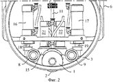
фиг.2 - частичный вид сбоку узла согласно фиг.1 во время резки и биговки,figure 2 is a partial side view of the node according to figure 1 during cutting and scoring,
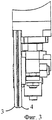
Фиг.3 - вид с торца фрагмента резального и биговального дискового узла во время биговки, иFigure 3 is an end view of a fragment of a cutting and scoring disk unit during scoring, and
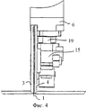
фиг.4 - вид, аналогичный фиг.3, изображающий резальный и биговальный дисковый узел во время резки и биговки гофрированного листового материала.figure 4 is a view similar to figure 3, depicting a cutting and creasing disk unit during cutting and creasing of corrugated sheet material.
ПОДРОБНОЕ ОПИСАНИЕ ВАРИАНТА ОСУЩЕСТВЛЕНИЯ ИЗОБРЕТЕНИЯDETAILED DESCRIPTION OF EMBODIMENTS OF THE INVENTION
Резальный и биговальный дисковый узел согласно предпочтительному варианту осуществления изобретения содержит круглый диск 1, имеющий режущую кромку 2, которая может быть выполнена ровной по всей окружности диска или зубчатой. Диск 1 установлен с возможностью вращения и перемещения между двумя половинами 3 и 4 биговального диска, установленными с возможностью вращения и имеющими одинаковый радиальный размер. В данном контексте выражение «половины биговального диска» относится к конструкции биговального диска, с помощью которой линия сгиба создается путем придавливания гофрированного материала или материала, сжимаемого за счет иных свойств, между двумя параллельными линиями, расположенными так близко друг от друга, что материал между ними сжимается и получается практически одна линия сгиба, позволяющая складывать материал на следующей завершающей операции. Круглым диском можно управлять для его перемещения между нерабочим положением (фиг.1 и 3), в котором режущая кромка вдвинута в радиальном направлении внутрь относительно наружных окружностей 5 половин биговального диска, и рабочим положением (фиг.2 и 4), в котором режущая кромка 2 выступает в радиальном направлении наружу относительно указанных окружностей 5.The cutting and creasing disk unit according to a preferred embodiment of the invention comprises a
При использовании резальный и биговальный дисковый узел устанавливается в машину для изготовления упаковочных заготовок из гофрированного или иного сжимаемого листового материала. Кронштейн, конструкция которого может быть приспособлена для бокового перемещения резального и биговального узла относительно машины, позиционирует узел относительно движущегося в машине листового материала так, что он входит в контакт с резальным и биговальным узлом, который выполняет в материале прорези и биговку в продольном и/или поперечном направлениях относительно направления движения материала. При необходимости, могут выполняться кривые или диагональные линии реза и сгиба благодаря соответствующим конструкции и управлению опорной конструкции. Как правило, резальный и биговальный узел связан с роликами, создающими противодавление (не показаны), несущими листовой материал с противоположной стороны и помогающими работе резального и биговального узла в направлении подачи, или с поперечным опорным элементом (не показан), движущимся поперек направления подачи и помогающим работе узла в поперечном направлении. На кронштейне закреплен или выполнен за одно целое с ним держатель 6, в котором, как будет описано ниже, находятся подшипники и приводное средство для управления вращением и перемещением половин 3, 4 биговального диска и режущего инструмента или диска 1.When using a cutting and scoring disk unit is installed in a machine for the manufacture of packaging blanks from corrugated or other compressible sheet material. An arm, the design of which can be adapted for lateral movement of the cutting and creasing unit relative to the machine, positions the unit relative to the sheet material moving in the machine so that it comes into contact with the cutting and creasing unit, which performs slotting and creasing in the material in the longitudinal and / or transverse directions relative to the direction of movement of the material. If necessary, curves or diagonal cut and bend lines can be made due to the appropriate design and control of the support structure. Typically, the cutting and scoring unit is associated with rollers that create back pressure (not shown), carrying sheet material from the opposite side and assisting the cutting and scoring unit in the feed direction, or with a transverse support element (not shown) moving across the feed direction and helping the operation of the node in the transverse direction. A
Биговальный диск в резальном и биговальном дисковом узле согласно изобретению содержит два кольца 3 и 4, каждое из которых имеет наружную и внутреннюю окружности. Кольца 3 и 4 имеют одинаковый наружный радиальный размер и, как правило, одинаковый внутренний радиальный размер. Кольца 3 и 4 направляются своими внутренними окружностями по роликам 7, 8 и 9, позволяющим кольцам свободно вращаться вокруг их центров, расположенных на общей оси вращения. Внутренние окружности обоих колец имеют фаски и входят в соответствующие канавки, образованные по окружности роликов. Наружные окружности колец 3, 4 скруглены к боковым сторонам, обращенным наружу от биговального диска, а их боковые стороны, обращенные друг к другу, могут составлять с наружными окружностями более острый угол. Кольца установлены с помощью цапф на роликах с осевым смещением, образуя достаточный зазор для перемещения диска 1 между кольцами в рабочее положение, как описано ниже.The scoring disk in the cutting and scoring disk unit according to the invention contains two
Ролики 7, 8 и 9 установлены с возможностью вращения на цапфах в подшипниках, расположенных на подъемном механизме 10, который направляется в держателе 6 с целью линейного перемещения по существу перпендикулярно к листовому материалу, т.е. в вертикальном направлении, когда листовой материал движется горизонтально под резальным и биговальным дисковым узлом. Подъемный механизм 10 содержит вертикальный шток 11, проходящий через держатель 6 и направляемый в нем с помощью отверстия, образованного в нижнем элементе держателя. На верхнем конце шток 11 несет ползун 12, в котором на цапфах установлен ролик 7 для половин 3, 4 биговального диска. Ползун 12 направляется по стойкам 13, 14, связанным с верхним элементом держателя 6, которые обеспечивают движение подъемного механизма без заклинивания. Нижний конец штока 11 соединен с горизонтальной балкой 15, на которой с помощью цапф установлены два ролика 8 и 9 для половин 3, 4 биговального диска.The
Управление рабочими положениями резального и биговального узла осуществляет силовой блок, действующий между держателем 6 и горизонтальной балкой 15. В данном варианте осуществления изобретения к держателю 6 прикреплены два пневмоцилиндра 16 и 17, а поршни 18, 19 цилиндров соединены с соответствующими концами горизонтальной балки 15. Длина поршней перекрывает расстояние, в пределах которого находятся подъемный механизм 10, горизонтальная балка 15, ролики 7, 8 и 9 и кольца или половины 3 и 4 биговального диска. Силовой блок может быть гидравлическим или электрическим.The operating positions of the cutting and scoring unit are controlled by a power unit acting between the
Режущий инструмент, т.е. диск 1, установлен на горизонтальной балке 15, говоря точнее, установлен с помощью цапф для свободного вращения в шарнирной опоре 20, соединенной с концами поршней двух цилиндровых блоков 21 и 22, установленных на горизонтальной балке 15. Посредством цилиндров 21 и 22, в данном случае пневматических, осуществляется управление перемещениями диска 1 между половинами биговального диска и относительно них из нерабочего положения, показанного на фиг.3, в котором режущая кромка 2 вдвинута внутрь относительно наружных окружностей 5 половин 3 и 4 биговального диска, в рабочее положение, показанное на фиг.4, в котором режущая кромка выступает радиально наружу относительно этих окружностей для контакта с материалом и выполнения в нем прорези.Cutting tool i.e. the
На практике предпочтительно, чтобы режущий инструмент или диск 1 выдвигался с помощью цилиндров 21, 22 для выполнения прорези в сжимаемом материале и одновременно приводились в действие половины 3, 4 биговального диска для сжатия материала, уменьшая тем самым его толщину, что исключает необходимость выполнять рез чрезмерной длины, например через верхний плоский слой и гофрированный слой гофрированного материала. Благодаря тому, что ножевой диск режет материал в зазоре между половинами "расщепленного" биговального диска, точки контакта материала с половинами биговального диска и ножевым диском расположены по существу на одной линии, параллельной оси вращения резального и биговального узла. Так как резка выполняется на материале с уменьшенной толщиной, можно использовать ножевые диски меньшего диаметра. Уменьшение диаметра позволяет уменьшить толщину диска и сделать минимальным зазор между половинами биговального диска. Иначе говоря, поскольку сжатие и резка выполняются одновременно в более или менее одном месте с использованием ножевого диска малых размеров, то согласно изобретению в машине для изготовления упаковочных заготовок можно существенно повысить точность выполнения прорезей в гофрированном или ином сжимаемом материале.In practice, it is preferable that the cutting tool or
Установка режущего инструмента с возможностью одновременной работы практически в одном месте с биговальным инструментом позволяет упростить проектирование конструкции упаковки и повысить производительность машины, производительность повышается потому, что обычно резку выполняют после биговки, чтобы избежать появление трещин. Для этого могут потребоваться холостой обратный ход инструмента или установка последовательно нескольких инструментов. Изобретение позволяет избежать и того и другого.The installation of a cutting tool with the possibility of simultaneous work in almost the same place with the scoring tool allows you to simplify the design of the packaging design and increase the productivity of the machine, productivity is increased because usually cutting is performed after scoring to avoid cracks. This may require a single tool reverse gear or the installation of several tools in series. The invention avoids both.
Кроме того, прохождение режущего инструмента через гофрированный материал занимает больше времени, чем время его прохождения через гофрированный материал в сжатом состоянии, когда инструмент должен выдвигаться всего на пару миллиметров. Эта разница в длине хода позволяет повысить производительность машины с сохранением точности резки, особенно когда при работе инструментов материал перемещается относительно узла или наоборот. Этот особенно важно, когда в гофрированном материале нужно сделать короткие прорези.In addition, the passage of the cutting tool through the corrugated material takes longer than the time of its passage through the corrugated material in a compressed state, when the tool should extend only a couple of millimeters. This difference in the length of the stroke allows you to increase the productivity of the machine while maintaining cutting accuracy, especially when the material moves relative to the assembly when working with tools or vice versa. This is especially important when short cuts need to be made in corrugated material.
Предпочтительный вариант осуществления изобретения является эффективным решением в отношении веса, что позволяет использовать биговальные диски большего радиуса, так как для получения линий сгиба, по которым материал легче складывать, посредством больших биговальных дисков можно приложить большее давление без растрескивания плоского бумажного слоя в гофрированном картоне.A preferred embodiment of the invention is an effective solution in terms of weight, which allows the use of scoring discs with a larger radius, since in order to obtain folding lines that make the material easier to fold, larger scoring discs can be applied with greater pressure without cracking the flat paper layer in the corrugated cardboard.
В данном варианте осуществления изобретения режущий инструмент представляет собой круглый диск, использование которого для гофрированного картона является предпочтительным. Однако между половинами биговального диска можно установить другие режущие инструменты и управлять ими для введения в контакт с материалом в одном месте с биговальным диском, состоящим из двух половин. Для достижения более точной резки сжатого участка сжимаемого материала в сочетании с биговальным диском, состоящим из двух половин, могут использоваться такие альтернативные инструменты, как лазерные резаки, водоструйные резаки, абразивные водоструйные резаки и недисковые ножи.In this embodiment, the cutting tool is a circular disc, the use of which for corrugated board is preferred. However, other cutting tools can be installed between the halves of the scoring disc and manipulated to bring them into contact with the material in one place with the scoring disc consisting of two halves. Alternative cutting tools such as laser cutters, water jet cutters, abrasive water jet cutters, and non-blade knives can be used to achieve more accurate cutting of a compressed portion of a compressible material in combination with a two-half scoring disc.
Хотя изобретение было описано на примере машины для изготовления упаковочных заготовок из движущегося листового материала, компактная конструкция резального и биговального дискового узла может использоваться в машинах, где неподвижно закрепленный материал обрабатывается одним или несколькими такими узлами, которые движутся относительно материала.Although the invention has been described with an example of a machine for manufacturing packaging blanks from a moving sheet material, the compact design of the cutting and creasing disk assembly can be used in machines where the fixed material is processed by one or more such assemblies that move relative to the material.
Claims (14)
Applications Claiming Priority (2)
| Application Number | Priority Date | Filing Date | Title |
|---|---|---|---|
| SE0500431-2 | 2005-02-25 | ||
| SE0500431 | 2005-02-25 |
Publications (2)
| Publication Number | Publication Date |
|---|---|
| RU2007135344A RU2007135344A (en) | 2009-03-27 |
| RU2397859C2 true RU2397859C2 (en) | 2010-08-27 |
Family
ID=36927691
Family Applications (1)
| Application Number | Title | Priority Date | Filing Date |
|---|---|---|---|
| RU2007135344A RU2397859C2 (en) | 2005-02-25 | 2006-02-22 | Cutting and creasing disk unit and procedure for compressed material cutting and creasing |
Country Status (14)
| Country | Link |
|---|---|
| US (1) | US7736289B2 (en) |
| EP (1) | EP1853410B1 (en) |
| JP (1) | JP4936396B2 (en) |
| CN (1) | CN101163577B (en) |
| AT (1) | ATE519572T1 (en) |
| AU (1) | AU2006217120B2 (en) |
| BR (1) | BRPI0607598B1 (en) |
| CA (1) | CA2598965C (en) |
| DK (1) | DK1853410T3 (en) |
| ES (1) | ES2371102T3 (en) |
| MX (1) | MX2007010425A (en) |
| PL (1) | PL1853410T3 (en) |
| RU (1) | RU2397859C2 (en) |
| WO (1) | WO2006091149A1 (en) |
Families Citing this family (29)
| Publication number | Priority date | Publication date | Assignee | Title |
|---|---|---|---|---|
| GB2460261B (en) * | 2008-05-22 | 2012-02-15 | Morgana Systems Ltd | Creasing machine |
| IT1392753B1 (en) * | 2009-01-27 | 2012-03-16 | Panotec Srl | TOOL TO CARRY OUT AT LEAST ONE CORDONATURE ON A RELATIVELY RIGID MATERIAL, SUCH AS A CARDBOARD EXAMPLE |
| CN102248300A (en) * | 2010-05-22 | 2011-11-23 | 武汉金运激光股份有限公司 | Laser cutting machine and laser processing method for packaging box |
| EP2474397B1 (en) | 2011-01-07 | 2013-07-03 | Ligmatech Automationssysteme GmbH | Cutting and grooving device and method for cutting and/or grooving |
| PL3243615T3 (en) * | 2011-11-10 | 2020-08-24 | Packsize Llc | Elevated converting machine for converting material into packaging templates |
| EP2802448B1 (en) | 2012-01-09 | 2016-10-26 | Packsize LLC | Converting machine with an upward outfeed guide |
| DE102012220233B4 (en) | 2012-11-07 | 2019-03-28 | Ligmatech Automationssysteme Gmbh | Processing device with a rotatable tool receiver |
| US10245803B2 (en) * | 2013-03-13 | 2019-04-02 | Xerox Corporation | Apparatus, system and method for cutting and creasing media |
| US10093438B2 (en) | 2014-12-29 | 2018-10-09 | Packsize Llc | Converting machine |
| CN104960245B (en) * | 2015-07-22 | 2017-08-01 | 青岛澳邦量器有限责任公司 | A kind of cardboard line ball cutting combination knife |
| DE102015011399B4 (en) | 2015-08-31 | 2020-01-23 | G. Kraft Maschinenbau Gmbh | Device and method for scoring, perforating, cutting and scoring flat elements |
| DE202015006139U1 (en) | 2015-08-31 | 2015-10-15 | G. Kraft Maschinenbau Gmbh | Device for scoring, perforating, cutting and scoring flat objects |
| CN109195783A (en) * | 2016-05-30 | 2019-01-11 | 海克恩系统有限公司 | System and method for forming fold line in the substrate |
| ES2848561T3 (en) | 2016-06-16 | 2021-08-10 | Packsize Llc | A box template production procedure and system |
| US10850469B2 (en) | 2016-06-16 | 2020-12-01 | Packsize Llc | Box forming machine |
| US11242214B2 (en) | 2017-01-18 | 2022-02-08 | Packsize Llc | Converting machine with fold sensing mechanism |
| SE541921C2 (en) | 2017-03-06 | 2020-01-07 | Packsize Llc | A box erecting method and system |
| SE540672C2 (en) | 2017-06-08 | 2018-10-09 | Packsize Llc | Tool head positioning mechanism for a converting machine, and method for positioning a plurality of tool heads in a converting machine |
| KR102021975B1 (en) * | 2017-11-28 | 2019-09-17 | 나승옥 | the improved packing paper cuttingmachine structure with possibility opening and shutting |
| US11173685B2 (en) | 2017-12-18 | 2021-11-16 | Packsize Llc | Method for erecting boxes |
| US11247427B2 (en) | 2018-04-05 | 2022-02-15 | Avercon BVBA | Packaging machine infeed, separation, and creasing mechanisms |
| US11305903B2 (en) | 2018-04-05 | 2022-04-19 | Avercon BVBA | Box template folding process and mechanisms |
| DE112019003075T5 (en) | 2018-06-21 | 2021-03-25 | Packsize Llc | PACKAGING DEVICE AND SYSTEMS |
| SE543046C2 (en) | 2018-09-05 | 2020-09-29 | Packsize Llc | A box erecting method and system |
| US11524474B2 (en) | 2018-11-30 | 2022-12-13 | Packsize Llc | Adjustable cutting and creasing heads for creating angled cuts and creases |
| DE112020000348T5 (en) | 2019-01-07 | 2021-09-16 | Packsize Llc | Carton erecting machine |
| CN109702811B (en) * | 2019-01-22 | 2020-10-16 | 宁夏成峰包装印刷有限公司 | Ring-moving die-cutting machine capable of being manually intervened for operation |
| US11701854B2 (en) | 2019-03-14 | 2023-07-18 | Packsize Llc | Packaging machine and systems |
| CN110271039A (en) * | 2019-06-06 | 2019-09-24 | 美科新能源(苏州)有限公司 | A kind of soft-package battery shell aluminum plastic film cutter device |
Family Cites Families (24)
| Publication number | Priority date | Publication date | Assignee | Title |
|---|---|---|---|---|
| JPS5316944B2 (en) * | 1973-09-21 | 1978-06-05 | ||
| GB1538001A (en) * | 1976-06-16 | 1979-01-10 | Molins Machine Co Inc | Apparatus for processing box blanks |
| CA1076020A (en) * | 1977-10-20 | 1980-04-22 | Rengo Co. | Tool positioning apparatus |
| US4596541A (en) * | 1983-09-09 | 1986-06-24 | The Ward Machinery Company | Slit-score method and apparatus |
| JPH0294A (en) * | 1985-01-31 | 1990-01-05 | Ricoh Co Ltd | Display device for character or the like |
| JPS62159958A (en) * | 1986-01-09 | 1987-07-15 | Tamura Electric Works Ltd | Automatic answering telephone set |
| JPS6479598A (en) * | 1987-09-21 | 1989-03-24 | Yasushi Yui | Method of shooting up display ball with cartridge case |
| JPH0634960Y2 (en) * | 1987-11-11 | 1994-09-14 | 三菱重工業株式会社 | Winding sheet surface layer sheet cutting device |
| FR2628999B1 (en) * | 1988-03-22 | 1990-12-07 | Martin Sa | DEVICE FOR QUICK ASSEMBLY AND DISASSEMBLY OF CIRCULAR TOOLS OR BLADES ON A SHAFT-TOOL HOLDER |
| DE3809778A1 (en) * | 1988-03-23 | 1989-10-05 | Bayer Ag | PYRIMIDINYL THIONOPHOSPHORIC ACID ESTER |
| US5125258A (en) * | 1989-01-23 | 1992-06-30 | Warner Richard L | Method and tools for forming sheet metal |
| US5533956A (en) * | 1992-02-24 | 1996-07-09 | Hexacomb Corporation | Method and apparatus for manufacturing articles employing folded honeycomb panels |
| US5466211A (en) * | 1992-02-24 | 1995-11-14 | Hexacomb Corporation | Method and apparatus for manufacturing articles employing folded honeycomb panels |
| US6007470A (en) * | 1992-02-24 | 1999-12-28 | Tenneco Packaging Inc. | Method and apparatus for manufacturing articles employing folded honeycomb panels |
| DE4308044C1 (en) * | 1993-03-13 | 1994-10-06 | Roland Man Druckmasch | Longitudinal cutting device for webs |
| US5596918A (en) * | 1994-04-21 | 1997-01-28 | The Upper Deck Company | Sports card slitting device and method |
| US5540128A (en) * | 1995-01-27 | 1996-07-30 | Lawrence Paper Company | Selectively retractable slutter blade mechanism with remote activation/deactivation function |
| JPH11510442A (en) * | 1995-08-10 | 1999-09-14 | ローレンス ペーパー カンパニー | Cutting wheel mechanism with selectively rotatable cutting blade |
| DE19754799A1 (en) * | 1997-12-10 | 1999-06-17 | Bhs Corr Masch & Anlagenbau | Slitting and creasing machine for corrugated cardboard webs |
| JP3676066B2 (en) * | 1997-12-24 | 2005-07-27 | ショーダテクトロン株式会社 | Method for cutting plate material having decorative plate |
| SE514189C2 (en) * | 1998-04-29 | 2001-01-22 | Emba Machinery Ab | Cardboard blank manufacturing unit |
| JP2003025277A (en) * | 2001-07-17 | 2003-01-29 | Chiyoda Container Corp | Cutter for cutting work of corrugated fiberboard plate |
| AU2002953443A0 (en) * | 2002-12-19 | 2003-01-09 | Modra Family Trust | A laser cutting apparatus |
| JP4399193B2 (en) * | 2003-03-27 | 2010-01-13 | 武藤工業株式会社 | Paper cutting device for recording device |
-
2006
- 2006-02-22 ES ES06716923T patent/ES2371102T3/en active Active
- 2006-02-22 JP JP2007556997A patent/JP4936396B2/en active Active
- 2006-02-22 BR BRPI0607598-3A patent/BRPI0607598B1/en not_active IP Right Cessation
- 2006-02-22 CA CA 2598965 patent/CA2598965C/en active Active
- 2006-02-22 EP EP20060716923 patent/EP1853410B1/en active Active
- 2006-02-22 MX MX2007010425A patent/MX2007010425A/en active IP Right Grant
- 2006-02-22 DK DK06716923T patent/DK1853410T3/en active
- 2006-02-22 AT AT06716923T patent/ATE519572T1/en active
- 2006-02-22 PL PL06716923T patent/PL1853410T3/en unknown
- 2006-02-22 AU AU2006217120A patent/AU2006217120B2/en active Active
- 2006-02-22 WO PCT/SE2006/000233 patent/WO2006091149A1/en active Application Filing
- 2006-02-22 US US11/817,038 patent/US7736289B2/en active Active
- 2006-02-22 RU RU2007135344A patent/RU2397859C2/en active
- 2006-02-22 CN CN2006800136560A patent/CN101163577B/en active Active
Also Published As
| Publication number | Publication date |
|---|---|
| CN101163577B (en) | 2011-01-19 |
| ES2371102T3 (en) | 2011-12-27 |
| EP1853410A1 (en) | 2007-11-14 |
| CN101163577A (en) | 2008-04-16 |
| JP4936396B2 (en) | 2012-05-23 |
| RU2007135344A (en) | 2009-03-27 |
| AU2006217120B2 (en) | 2011-08-18 |
| CA2598965C (en) | 2012-07-24 |
| ATE519572T1 (en) | 2011-08-15 |
| CA2598965A1 (en) | 2006-08-31 |
| BRPI0607598A2 (en) | 2009-09-15 |
| EP1853410B1 (en) | 2011-08-10 |
| AU2006217120A1 (en) | 2006-08-31 |
| WO2006091149A1 (en) | 2006-08-31 |
| MX2007010425A (en) | 2008-02-12 |
| US7736289B2 (en) | 2010-06-15 |
| BRPI0607598B1 (en) | 2018-06-26 |
| JP2008531304A (en) | 2008-08-14 |
| DK1853410T3 (en) | 2011-11-21 |
| EP1853410A4 (en) | 2010-06-02 |
| US20080148917A1 (en) | 2008-06-26 |
| PL1853410T3 (en) | 2012-01-31 |
Similar Documents
| Publication | Publication Date | Title |
|---|---|---|
| RU2397859C2 (en) | Cutting and creasing disk unit and procedure for compressed material cutting and creasing | |
| JP4724319B2 (en) | Vertical processing machine for corrugated web | |
| JP6393456B2 (en) | Cutting unit | |
| CN102753318B (en) | Rotary working apparatus | |
| US20080066597A1 (en) | Rotary die cutter | |
| JPS591591B2 (en) | Slipper/scorer device | |
| US7789001B2 (en) | Core reduction method and apparatus | |
| JP6635344B2 (en) | Cutting equipment for cutting paper, corrugated cardboard, plastics, composites or such relatively rigid materials | |
| JP4544985B2 (en) | Corrugated sheet processing apparatus and corrugated sheet processing method | |
| CN101254598B (en) | Flimsy guillotining mechanism with spiral curve corner upper knife edge and knife edge structure | |
| JP5835901B2 (en) | Trimming method, corrugating machine and edge cutting device in corrugating machine | |
| WO2005095069A1 (en) | Severing machine with central sharpening system | |
| IT201800010637A1 (en) | PERFORATING DEVICE AND TRANSFORMATION MACHINE INCLUDING SAID DEVICE | |
| EP2095917B1 (en) | Tissue paper cutting mechanism having upper knife with variable spiral curve angle and upper knife structure therefor | |
| CN220429482U (en) | Grooving device for pressing line | |
| KR200345816Y1 (en) | Glasswool slitting machine | |
| JP2002036399A (en) | Slitter scorer | |
| EP3272688B1 (en) | Perforator assembly for rewinder of sheet material | |
| JPS6257480B2 (en) | ||
| KR20200000854A (en) | Die cutter | |
| KR20220036747A (en) | Multi working apparatus conduting cutiing and milling | |
| WO2003086720A1 (en) | Sheet cutter with inclined cutting edge | |
| RU2179514C1 (en) | Method of cross cutting of blanks of preset length from continuously moving material web | |
| JPH06335892A (en) | Slitting device | |
| JPS62120909A (en) | Shearing machine for shear line |