RU2391883C2 - Production of filters for tobacco smoke - Google Patents
Production of filters for tobacco smoke Download PDFInfo
- Publication number
- RU2391883C2 RU2391883C2 RU2007120343/12A RU2007120343A RU2391883C2 RU 2391883 C2 RU2391883 C2 RU 2391883C2 RU 2007120343/12 A RU2007120343/12 A RU 2007120343/12A RU 2007120343 A RU2007120343 A RU 2007120343A RU 2391883 C2 RU2391883 C2 RU 2391883C2
- Authority
- RU
- Russia
- Prior art keywords
- injection
- additive
- solid particles
- channel
- filter
- Prior art date
Links
Images


Classifications
-
- A—HUMAN NECESSITIES
- A24—TOBACCO; CIGARS; CIGARETTES; SIMULATED SMOKING DEVICES; SMOKERS' REQUISITES
- A24D—CIGARS; CIGARETTES; TOBACCO SMOKE FILTERS; MOUTHPIECES FOR CIGARS OR CIGARETTES; MANUFACTURE OF TOBACCO SMOKE FILTERS OR MOUTHPIECES
- A24D3/00—Tobacco smoke filters, e.g. filter-tips, filtering inserts; Filters specially adapted for simulated smoking devices; Mouthpieces for cigars or cigarettes
- A24D3/02—Manufacture of tobacco smoke filters
- A24D3/0204—Preliminary operations before the filter rod forming process, e.g. crimping, blooming
- A24D3/0212—Applying additives to filter materials
- A24D3/0225—Applying additives to filter materials with solid additives, e.g. incorporation of a granular product
-
- A—HUMAN NECESSITIES
- A24—TOBACCO; CIGARS; CIGARETTES; SIMULATED SMOKING DEVICES; SMOKERS' REQUISITES
- A24D—CIGARS; CIGARETTES; TOBACCO SMOKE FILTERS; MOUTHPIECES FOR CIGARS OR CIGARETTES; MANUFACTURE OF TOBACCO SMOKE FILTERS OR MOUTHPIECES
- A24D3/00—Tobacco smoke filters, e.g. filter-tips, filtering inserts; Filters specially adapted for simulated smoking devices; Mouthpieces for cigars or cigarettes
- A24D3/02—Manufacture of tobacco smoke filters
Abstract
Description
Изобретение относится к фильтрам для табачного дыма и предлагает способ производства фильтров для табачного дыма, в котором непрерывный материал, фильтрующий табачный дым, непрерывно продвигается вперед в продольном направлении и уплотняется до формы стержня; уплотненный, перемещающийся вперед фильтрующий материал формуется и закрепляется в виде стержня, а полученный непрерывно выпускаемый стержень фильтрующего материала может быть нарезан на отрезки конечной длины, причем в способе используется периодическая пневматическая инжекция добавки твердого вещества (например, через инжекционный цилиндр или канал, который предпочтительно является стационарным) сбоку в продвигающийся вперед уплотняющийся фильтрующий материал с образованием отдельных включений добавки твердых частиц, заделанных в непрерывно выпускаемом стержне и расположенных вдоль него с промежутками. В некоторых вариантах выполнения имеет место последовательная пневматическая инжекция отдельных включений добавки из твердых частиц (например, через неподвижно закрепленный инжекторный канал) сбоку в продвигающийся вперед уплотняющийся фильтрующий материал, так что заделывается в непрерывно выпускаемом стержне и располагается в нем продольно с промежутками.The invention relates to filters for tobacco smoke and provides a method for producing filters for tobacco smoke, in which a continuous material filtering tobacco smoke is continuously advanced in the longitudinal direction and compacted to form a rod; a sealed, moving forward filter material is molded and fixed in the form of a rod, and the resulting continuously produced filter material rod can be cut into segments of finite length, and the method uses periodic pneumatic injection of a solid additive (for example, through an injection cylinder or channel, which is preferably stationary) on the side of the compacting filtering material advancing forward with the formation of individual inclusions of the additive of solid particles embedded h is continuously discharged rod and arranged at intervals along it. In some embodiments, sequential pneumatic injection of individual particulate additives (for example, through a fixed injection channel) takes place laterally into the filter filter material advancing forward, so that it is sealed in the continuously discharged rod and is positioned longitudinally at intervals.
Предложенное устройство, предназначенное для производства фильтров для табачного дыма, содержит приспособление для непрерывного продвижения в продольном направлении последовательности материала, фильтрующего табачный дым, приспособление для уплотнения продвигающегося вперед фильтрующего материала, штранговый аппарат для формования и закрепления перемещающегося уплотненного фильтрующего материала в форме стержня, дополнительное ножевое устройство для резки в поперечном направлении непрерывно выпускаемого стержня на отрезки конечной длины, пневматический инжекторный канал (как правило, неподвижно закрепленный), выполненный с возможностью соединения с приспособлением, подающим в него добавки из твердых частиц, а также приспособление для пневматической инжекции, предназначенное для периодического впуска добавки из твердых частиц в инжекторный канал и перемещения ее вдоль него, при этом инжекторный канал проходит в боковом направлении к траектории движения фильтрующего материала для поперечной подачи внутри обжимного приспособления. В некоторых вариантах выполнения приспособление для пневматической инжекции последовательно перемещает отдельные включения добавки из твердых частиц из указанного подающего приспособления вдоль инжекторного канала (который обычно является стационарным).The proposed device designed for the production of filters for tobacco smoke, contains a device for continuously moving in longitudinal direction the sequence of material filtering tobacco smoke, a device for sealing a moving forward filter material, an extruder for forming and fixing a moving compacted filter material in the form of a rod, an additional knife device for cutting in the transverse direction of a continuously produced rod into of finite length, a pneumatic injection channel (usually fixedly mounted) made with the possibility of connection with a device supplying additives from it to solid particles, as well as a device for pneumatic injection, intended for periodic intake of an additive from solid particles into the injection channel and moving it along it, while the injection channel passes laterally to the trajectory of the filter material for lateral feed inside the crimping device. In some embodiments, the pneumatic injection device sequentially moves the individual particulate additive inclusions from said feed device along the injection channel (which is usually stationary).
Газ, используемый для пневматической инжекции частиц, можно удалить из уплотняющегося фильтрующего материала. Дополнительно или вместо этого некоторые, большинство или все газы, используемые для пневматической инжекции частиц, можно выпустить или вытянуть перед местом инжекции частиц. Во всех случаях импульс, толчок или кинетическая энергия, пневматически передаваемая частицам, предназначенным для образования включения (в отличие от ненужных мелких и/или других частиц), достаточна для обеспечения их перемещения к уплотняющемуся фильтрующему материалу и введения в него. Таким образом, должно быть понятно, что в данном документе все ссылки на выражения «пневматическое перемещение», «пневматическая инжекция», «пневматическое перемещение и инжекция» и подобные им относятся по смыслу не только к случаям, когда некоторые или все из указанных газов проходят в уплотняющийся фильтрующий материал вместе с частицами, но также к случаям, когда газа мало или нет вообще из-за того, что его основная часть выпущена или удалена перед этим. Уменьшение или отсутствие выпуска газа для пневматической инжекции в уплотняющийся фильтрующий материал может уменьшить или предотвратить распыление или рассеивание частиц, введенных в указанный материал, и таким образом улучшить точность формирования включения и интервалы между включениями в готовом стержне.The gas used for pneumatic injection of particles can be removed from the densified filter material. Additionally or instead, some, most or all of the gases used for pneumatic injection of particles can be discharged or extended in front of the particle injection site. In all cases, the impulse, impulse, or kinetic energy transmitted pneumatically to particles intended to form an inclusion (as opposed to unnecessary small and / or other particles) is sufficient to allow them to move to and be introduced into the densified filter material. Thus, it should be understood that in this document all references to the expressions “pneumatic displacement”, “pneumatic injection”, “pneumatic displacement and injection” and the like refer not only to the cases where some or all of these gases pass into a densified filter medium together with particles, but also to cases when there is little or no gas at all due to the fact that its main part is released or removed before that. Reducing or not releasing gas for pneumatic injection into the densified filter material can reduce or prevent atomization or dispersion of particles introduced into said material, and thus improve the accuracy of inclusion formation and the intervals between inclusions in the finished rod.
Прохождение и инжекция добавки из твердых частиц поперек (а не аксиально вдоль) и, главным образом, радиально траектории движения фильтрующего материала позволяет уменьшить или минимизировать время и расстояние пневматического перемещения добавки в фильтрующий материал и, следовательно, может обеспечить разделение окончательных включений добавок, а также оптимизировать точность, надежность и управляемость включениями добавок. Инжекция поперек, особенно радиально направлению работы оборудования, может минимизировать рассеивание введенных добавок из твердых частиц вдоль указанного стержня и таким образом уменьшить или исключить наличие нежелательных лишних инжектированных частиц между включениями или на концах (либо слишком близко к ним) отрезков разрезанного фильтра.The passage and injection of the additive from solid particles across (rather than axially along) and, mainly, radially the trajectory of the filter material allows to reduce or minimize the time and distance of pneumatic movement of the additive in the filter material and, therefore, can ensure the separation of the final inclusions of additives, as well as optimize accuracy, reliability and controllability of additives. Injection across, especially radially to the direction of operation of the equipment, can minimize the dispersion of the introduced additives from solid particles along the specified rod and thus reduce or eliminate the presence of undesirable excess injected particles between the inclusions or at the ends (or too close to them) of the cut filter sections.
Предпочтительно, чтобы пневматическое перемещение добавки из твердых частиц к месту инжекции было как можно короче и, следовательно, было соответственно прямолинейным или по сути таковым; например, длина указанной траектории может составлять 170 мм, более предпочтительно 150 мм или менее, для фильтров стандартного размера и содержания, которые описаны далее. В особо предпочтительных вариантах выполнения длина указанной траектории может составлять около 135 мм или даже менее; разумеется, использование инжекторного канала, проходящего от внешнего источника частиц к обжимному приспособлению, должно предполагать минимально возможную длину. Боковое пневматическое перемещение и инжекция добавки из твердых частиц могут быть, по существу, радиальными (то есть под прямым углом) относительно оси перемещающегося вперед уплотняющегося фильтрующего материала; в этом случае траектория пневматического перемещения добавки из твердых частиц будет проходить через стенку приспособления, используемого для уплотнения материала. В альтернативном варианте боковое пневматическое перемещение и инжекция добавки из твердых частиц могли бы быть не перпендикулярными оси траектории фильтрующего материала; если данное перемещение и инжекция проводятся в том же общем направлении, что и продвижение фильтрующего материала, то в таком случае траектория пневматического перемещения частиц могла бы проходить скорее наклонно через пространство перед входным отверстием обжимного приспособления, чем через его стенку.Preferably, the pneumatic movement of the additive from the solid particles to the injection site is as short as possible and, therefore, is accordingly rectilinear or essentially such; for example, the length of the specified path may be 170 mm, more preferably 150 mm or less, for filters of standard size and content, which are described below. In particularly preferred embodiments, the length of said path may be about 135 mm or even less; Of course, the use of an injection channel extending from an external source of particles to a crimping tool should assume the smallest possible length. Lateral pneumatic movement and injection of the particulate additive can be substantially radial (i.e., at right angles) relative to the axis of the forward moving filter material; in this case, the trajectory of the pneumatic movement of the additive from the solid particles will pass through the wall of the device used to seal the material. Alternatively, the lateral pneumatic movement and injection of the particulate additive might not be perpendicular to the axis of the path of the filter material; if this movement and injection are carried out in the same general direction as the advancement of the filter material, then in this case the trajectory of the pneumatic movement of the particles could pass obliquely through the space in front of the inlet of the crimping device rather than through its wall.
Для реализации и последующего использования исходный, непрерывно выпускаемый стержень, как правило, нужно нарезать на отрезки конечной длины, желательно в ходе непрерывного процесса или работы устройства. Чтобы обеспечить заданный интервал между резами вдоль непрерывно выпускаемого стержня, а также заданное общее позиционирование резов (например, чтобы линии отреза проходили между внедренными включениями добавки из твердых частиц, а не через них для того, чтобы концы отрезка фильтрового стержня имели четкие края), предпочтительно чтобы резак был согласован с количеством пропускаемого через установку фильтрующего материала (например, с машинным приводом), а процесс инжекции был синхронизирован с резаком - инжектор предпочтительно управляется резаком. Однако в рамках такой синхронизации процессы пневматического перемещения и инжекции можно отрегулировать для получения более характерного заданного расположения внедренных включений вдоль отрезков стержня, например, по направлению к их центрам или концам.For implementation and subsequent use, the initial, continuously produced rod, as a rule, needs to be cut into pieces of finite length, preferably during a continuous process or operation of the device. In order to ensure a predetermined spacing between cuts along a continuously discharged rod, as well as a predetermined overall positioning of the cuts (for example, so that cut lines extend between embedded particulate additives and not through them so that the ends of a length of the filter rod have clear edges), preferably so that the cutter is consistent with the amount of filter material passed through the installation (for example, with a machine drive), and the injection process is synchronized with the cutter - the injector is preferably controlled is a cutter. However, in the framework of such synchronization, the processes of pneumatic movement and injection can be adjusted to obtain a more characteristic predetermined location of the embedded inclusions along the segments of the rod, for example, in the direction of their centers or ends.
В фильтрах согласно изобретению внедренные включения добавок могут быть полностью включены в основу фильтрующего материала и иметь сжатую форму, а могут сужаться по направлению к одному или обоим концам, например, как правило, могут иметь форму эллипса. В начально выпускаемом стержне внедренные включения добавки могут иметь даже вытянутое расположение. Однако предпочтительными могут быть и иные расположения включения - например, сравнительно короткий продольный интервал чередуется с более длинным интервалом - такое расположение можно получить путем соответствующего регулирования времени и последовательности инжекции; это может способствовать получению конечных единичных фильтров с единичным включением добавки, расположенным ближе к одному концу (предпочтительно табачному концу в сигарете с фильтром) и дальше от другого конца (предпочтительно того конца, который находится ближе ко рту курильщика), как описано ниже со ссылкой на фиг.4. Каждый из индивидуальных фильтров согласно изобретению, как правило, имеет отдельно расположенное включение добавки из твердых частиц, но в альтернативном варианте в индивидуальном фильтре могло бы находиться несколько более мелких подобных включений, расположенных с интервалами в продольном направлении. Фильтр согласно изобретению может быть прикреплен торец в торец к обернутому табачному стержню (например, при помощи приклеивания ободка или приклеивания всей внешней обертки) в сигарете с фильтром согласно изобретению.In the filters according to the invention, the incorporated inclusions of additives can be fully incorporated into the base of the filter material and have a compressed shape, and can taper towards one or both ends, for example, as a rule, can be in the form of an ellipse. In the initial production rod, the incorporated additives inclusions can even have an elongated arrangement. However, other inclusion arrangements — for example, a relatively short longitudinal interval alternating with a longer interval — may be preferred — this arrangement can be obtained by appropriately adjusting the timing and injection sequence; this may facilitate the production of single end filters with a single inclusion of an additive located closer to one end (preferably the tobacco end in a filter cigarette) and further from the other end (preferably the end that is closer to the smoker's mouth), as described below with reference to figure 4. Each of the individual filters according to the invention, as a rule, has a separately located inclusion of an additive from solid particles, but in the alternative, an individual filter could contain several smaller such inclusions located at intervals in the longitudinal direction. The filter according to the invention can be attached end-to-end to a wrapped tobacco rod (for example, by gluing a rim or gluing the entire outer wrapper) in a filter cigarette according to the invention.
Любой фильтр или сигарету с фильтром согласно изобретению можно отперфорировать. Таким образом, если фильтр имеет собственную обертку, последняя может представлять собой, по сути, воздухопроницаемый материал и/или иметь перфорационные или более крупные отверстия, которые могут не перекрываться при использовании совместно с приклеенным ободком в сигарете с фильтром. Перфорационная, приклеенная по всей длине внешняя обертка может также быть воздухопроницаемой в своей основе и/или иметь перфорационные отверстия, а в перфорированных изделиях, которые имеют как обертку фильтра, так и приклеенную внешнюю обертку, перфорация через внешнюю обертку обычно будет совпадать с перфорацией через обертку фильтра. Перфорационные отверстия, проходящие через обертку фильтра, или через приклеенную внешнюю обертку, или через обе одновременно, могут быть выполнены лазерной перфорацией во время производства фильтров или сигарет с фильтром. Если перфорация в фильтре или в сигарете с фильтром согласно изобретению расположена продольно изделию, такое расположение предпочтительнее на одном или двух перечисленных ниже участках: перед включением добавки из твердых частиц, за ней, а также в совмещении с ней, в зависимости от заданных показателей перфорации и фильтрации; часто предпочтительной является перфорация перед включением добавки из твердых частиц и/или в совмещении с ней. При наличии двух или более включений между ними необходима перфорация. Возможна перфорация только в отрезке табачного стержня, только в фильтре или и в том и в другом. Плотность перфорации может составлять 50% или менее (например, 40%, или 30%, или ниже), но предпочтительно более 50% (например, 60%, или 70%, или выше), как определено соответствующим стандартом в этой области.Any filter or filter cigarette according to the invention can be perforated. Thus, if the filter has its own wrapper, the latter can be essentially breathable material and / or have perforation or larger holes that may not overlap when used together with the glued rim in a filter cigarette. Perforated, overlaid over the entire length of the outer wrapper can also be breathable at the core and / or have perforations, and in perforated products that have both a filter wrapper and a glued outer wrapper, perforation through the outer wrapper will usually coincide with perforation through the wrapper filter. Perforations passing through the filter wrapper, or through the glued outer wrapper, or both at the same time, can be laser perforated during the manufacture of filters or filter cigarettes. If the perforation in the filter or in the filter cigarette according to the invention is located longitudinally to the product, such an arrangement is preferable in one or two of the following areas: before switching on the particulate additive, behind it, as well as in combination with it, depending on the specified perforation and filtering; perforation is often preferred before incorporating the particulate additive and / or in combination with it. If there are two or more inclusions between them, perforation is necessary. Perforation is possible only in a segment of a tobacco rod, only in a filter, or both. The perforation density may be 50% or less (e.g., 40%, or 30%, or lower), but preferably more than 50% (e.g., 60%, or 70%, or higher), as defined by the relevant standard in this field.
Изобретение позволяет эффективное производство в промышленном масштабе в режиме однопроходного непрерывного процесса соответствующих комбинированных фильтров, имеющих участки обособленных частиц и фильтрующей основы.The invention allows efficient production on an industrial scale in a single-pass continuous process of the corresponding combined filters having sections of separate particles and a filter base.
Добавки из твердых частиц, используемые в изобретении, могут представлять собой любой подходящий для курения материал, но, как правило, будут состоять из материалов, обычно используемых в производстве фильтров табачного дыма, включающих сорбенты (например, из активированного угля, силикагеля, сепиолита, оксида алюминия, ионообменного материала и т.д.), модификаторы кислотности (например, щелочные вещества, такие как карбонат натрия, кислотные вещества) и ароматизаторы. Как правило, это будут сорбирующие частицы, предпочтительно частицы углерода - главным образом гранулы активированного угля. Могут использоваться смеси различных твердых частиц. Основа (например, сорбент) может содержать ароматизаторы, например ментол.The particulate additives used in the invention can be any smoking material, but will typically consist of materials commonly used in the manufacture of tobacco smoke filters, including sorbents (e.g., activated carbon, silica gel, sepiolite, oxide aluminum, ion exchange material, etc.), acidity modifiers (for example, alkaline substances such as sodium carbonate, acidic substances) and flavorings. As a rule, these will be sorbent particles, preferably carbon particles - mainly activated carbon granules. Mixtures of various solid particles may be used. The base (for example, sorbent) may contain flavorings, for example menthol.
Более того, в качестве фильтрующего материала, образующего основу стержня, внутрь которого внедрены включения добавки, может быть выбран любой из указанных материалов (обычно нитевидных, волокнистых, тканых или прессованных), традиционно используемых для производства фильтров табачного дыма. Предпочтительным материалом фильтрующей основы является натуральный или синтетический жгут, например, из хлопка или такого пластика, как полиэтилен или полипропилен, но главным образом ацетилцеллюлозный волокнистый жгут, но, кроме или вместо этого, можно использовать другие традиционные материалы, например натуральные или синтетические штапельные волокна, вату, тонколистовой материал, такой как бумага (обычно крепированная), а также синтетический нетканый и прессованный материал (например, крахмальные синтетические пенопласты). В процессе формования и закрепления фильтрующего материала в виде стержня может применяться обычная обертка для фильтра (которая может пропускать или не пропускать воздух), закрепленная обычным способом внахлестку клеевым швом; там, где фильтрующий материал включает клей, способный активироваться при нагревании, применение тепла в процессе формования стержня может скрепить фильтрующий материал вместе без использования обертки для фильтра, создавая стержень, который является плотным и не имеет отклонений по размерам - хотя, если оказывается предпочтение обертке для фильтра, она тем не менее может быть предусмотрена.Moreover, any of these materials (usually whisker, fibrous, woven or pressed) traditionally used for the manufacture of tobacco smoke filters can be selected as the filter material forming the core of the core into which the inclusions of the additive are embedded. The preferred material of the filter base is a natural or synthetic tow, for example, from cotton or plastic such as polyethylene or polypropylene, but mainly cellulose acetate tow, but other than traditional materials, for example natural or synthetic staple fibers, can be used, cotton, a sheet material such as paper (usually creped), and synthetic non-woven and extruded material (for example, starch synthetic foams). In the process of molding and fixing the filter material in the form of a rod, a conventional filter wrapper can be used (which may or may not allow air to pass), fixed in the usual way with an overlap with an adhesive seam; where the filter material includes an adhesive capable of being activated by heating, the use of heat during the formation of the rod can hold the filter material together without using a filter wrapper, creating a filter rod that is dense and deviates in size - although if wrapper is preferred for filter, it can nevertheless be provided.
Обычно добавка из твердых частиц хранится в резервуаре под давлением сжатого воздуха, который подает его в инжекторный канал или цилиндр. Хорошо, чтобы данный инжекторный канал или цилиндр проходил через резервуар; это обеспечивает компактную и рациональную систему и позволяет минимизировать расстояние и время пневматического перемещения добавки через инжектор в уплотняющийся фильтрующий материал.Typically, the particulate additive is stored in a tank under the pressure of compressed air, which feeds it into the injection channel or cylinder. It is good that the given injection channel or cylinder passes through the reservoir; this provides a compact and rational system and allows you to minimize the distance and time of pneumatic movement of the additive through the injector into the sealing filter material.
В некоторых предпочтительных вариантах выполнения добавка из твердых частиц постоянно проходит к пневматическому инжекторному каналу, в который подаются последовательные импульсы находящегося под давлением транспортирующего газа, необходимые для указанной периодической инжекции; таким образом, последовательные импульсы находящегося под давлением транспортирующего газа могут переносить последовательные, расположенные на определенном расстоянии включения добавок твердых частиц сбоку в уплотняющийся фильтрующий материал. Для данной скорости прохода фильтрующего материала размер и расположение добавок из твердых частиц, заделанных в указанном стержне, зависят от частоты импульсов и скорости подачи добавки из твердых частиц (например, из вышеописанного резервуара) в канал.In some preferred embodiments, the particulate additive continuously passes to a pneumatic injection channel into which successive pulses of a pressurized conveying gas are supplied necessary for said periodic injection; in this way, successive pulses of a pressurized conveying gas can carry sequential pulses of solid particles at a certain distance to turn on the side of the particulate admixture into the sealing filter material. For a given passage speed of filter material, the size and location of the additives from the solid particles embedded in the specified rod depend on the pulse frequency and the feed rate of the additive from the solid particles (for example, from the tank described above) into the channel.
В других вариантах выполнения добавка из твердых частиц периодически подается к пневматическому инжекторному каналу при помощи клапана, который циклически перемещается или переключается между открытым и закрытым положениями, а добавка из твердых частиц, поступающая в канал во время открытия клапана, перемещается вдоль канала потоком транспортирующего газа, предназначенного для указанных периодических боковых инжекций. Таким образом, частицы можно подавать из резервуара или другого подающего приспособления к инжекторному каналу посредством указанного клапана; поток высокоскоростного транспортирующего газа (и/или газа, имеющего высокую объемную скорость течения), непрерывно проходит по инжекторному каналу, так что, когда включение добавки из твердых частиц поступает во время открытого на мгновение клапана, она независимо перемещается вдоль инжекторного канала и вводится в уплотняющийся фильтрующий материал. Однако, несмотря на то, что клапан открыт лишь на мгновение, поток частиц может фактически непрерывно проходить через него сверх ограниченного времени его открытия (например, увеличиваясь, а затем уменьшаясь, если клапан открывается и закрывается постепенно), а скорость пневматического перемещения и инжекции может быть настолько высокой, что каждая частица по мере ее поступления в канал переносится фактически мгновенно в уплотняющийся фильтрующий материал, где происходит образование включения. Во всех случаях скорость пневматического перемещения и инжекции относительно более медленного продвижения фильтрующего материала обеспечивает образование готового стержня с компактными включениями из твердых частиц, имеющими четкие границы и расположенными с интервалами вдоль длины стержня. Работа клапана предпочтительно управляется резаком для предотвращения разрезания через включения, но точное позиционирование включений вдоль отрезков стержня можно получить путем регулировки режима синхронизированной работы клапана. Для данной скорости перемещения и инжекции размер внедренных включений зависит от скорости подачи к каналу добавок из твердых частиц (которая, в свою очередь, может в значительной степени зависеть от размера впускного отверстия открытого клапана), а также от продолжительности и быстродействия клапана (который может, например, приводиться в действие электрически или пневматически); расположение включений также зависит от продолжительности работы клапана.In other embodiments, the particulate additive is periodically supplied to the pneumatic injection channel by means of a valve that cyclically moves or switches between open and closed positions, and the particulate additive entering the channel during valve opening is moved along the channel by a flow of conveying gas, intended for said periodic lateral injections. Thus, particles can be supplied from a reservoir or other supply device to the injection channel by means of said valve; the flow of the high-speed carrier gas (and / or gas having a high volumetric flow rate) continuously passes through the injection channel, so that when the inclusion of the additive from the solid particles arrives during the momentarily open valve, it independently moves along the injection channel and is introduced into the sealing filter material. However, despite the fact that the valve is open only for a moment, the particle flow can actually continuously pass through it beyond the limited time of its opening (for example, increasing and then decreasing if the valve opens and closes gradually), and the speed of pneumatic movement and injection can be so high that each particle, as it enters the channel, is transferred almost instantly into the densified filter material, where inclusion is formed. In all cases, the speed of pneumatic movement and injection of a relatively slower advance of the filter material ensures the formation of a finished rod with compact inclusions of solid particles having clear boundaries and spaced at intervals along the length of the rod. The operation of the valve is preferably controlled by a torch to prevent cutting through the inclusions, but the precise positioning of the inclusions along the lengths of the shaft can be obtained by adjusting the synchronized operation of the valve. For a given speed of movement and injection, the size of the embedded inclusions depends on the feed rate of additives from the solid particles to the channel (which, in turn, can largely depend on the size of the inlet of the open valve), as well as on the duration and speed of the valve (which can, e.g. driven electrically or pneumatically); location of inclusions also depends on the duration of the valve.
Как отмечено в общих чертах выше, пневматический транспортирующий газ можно выпустить из фильтрующего материала до того, как последний сконцентрируется до формы стержня, например, при помощи выпускных отверстий, проходящих через стенку обжимного приспособления. Данный газ может дополнительно или вместо этого выпускаться в сторону из инжекционного канала или цилиндра перед его отверстием для выпуска частиц (и предпочтительно снаружи фильтрующего материала или снаружи обжимного приспособления) при прямом содействии внешнего всасывания или без него; если такой боковой выпуск осуществляется главным образом при помощи вакуума, скорость вытяжки газа может быть достаточно высокой, чтобы не позволить даже небольшому количеству транспортирующего газа достичь отверстия для выпуска частиц и выйти из него, и, следовательно, исключить необходимость выпуска газа из уплотняющегося фильтрующего материала; высокая объемная скорость такого вакуумного потока (например, выше, чем объемная скорость входного потока) перед инжекцией частиц может уменьшить или предотвратить нежелательную инжекцию пыли и мелких частиц добавки в уплотняющийся фильтрующий материал, тогда как более крупные частицы добавки, предназначенные для образования включения и за счет потока транспортирующего газа легко получившие ускорение до высоких скоростей (например, 100-200 м/с или выше), продолжают движение к инжекционному отверстию для выпуска частиц и через него, без особого снижения скорости.As outlined above, the pneumatic conveying gas can be discharged from the filter material before the latter is concentrated to the shape of the rod, for example, by means of outlets passing through the wall of the crimping device. This gas may additionally or instead be discharged to the side from the injection channel or cylinder in front of its particle outlet (and preferably outside the filter material or outside the crimping device) with or without direct external suction; if such lateral discharge is carried out mainly by means of vacuum, the gas extraction rate may be high enough to prevent even a small amount of conveying gas from reaching and leaving the particle outlet, and, therefore, eliminate the need for gas to escape from the sealing filter material; the high bulk velocity of such a vacuum flow (for example, higher than the bulk velocity of the inlet stream) before particle injection can reduce or prevent the unwanted injection of dust and small particles of the additive into the densified filter material, while larger particles of the additive intended to form an inclusion and due to the flow of the transporting gas, easily accelerated to high speeds (for example, 100-200 m / s or higher), continues to move to the injection hole to release particles through it, without God speed reduction.
Во всех случаях пневматическое перемещение и инжекция частиц радиально фильтрующему материалу имеет преимущества, описанные выше. Однако вышеописанная особенность по сути мгновенного пневматического перемещения последовательных частиц к фильтрующему материалу с образованием включения исключительно в фильтрующем материале и с завершением его только после инжекции также может быть успешно использована для периодической пневматической инжекции частиц и/или инжекции, не перпендикулярной (в том числе аксиальной) траектории перемещения фильтрующего материала. Аналогично выпуск или вытяжка пневматического транспортирующего газа перед инжекцией частиц также может быть успешно использована для периодической инжекции частиц с пневматическим переносом частиц и/или инжекции, не перпендикулярной (в том числе аксиальной) траектории перемещения фильтрующего материала; в этих случаях особенно важным может быть вакуумное удаление такого газа перед данной инжекцией частиц, главным образом при высокой объемной скорости выходного потока с целью получения высокого качества продукции. Согласно другому аспекту изобретения предложен способ и оборудование для изготовления фильтров табачного дыма с отдельными включениями добавки из твердых частиц, вытянутых вдоль фильтра; в данном способе последовательность материала, фильтрующего табачный дым, непрерывно перемещают вперед в продольном направлении, продвигающийся материал обжимают до формы стержня, добавку из твердых частиц пневматически вводят в продвигающийся уплотняющийся материал при помощи потока транспортирующего газа, а продвигающийся уплотняющийся материал с введенной добавкой формуют и закрепляют в виде стержня, причем добавку из твердых частиц периодически подают в поток транспортирующего газа при помощи, например, клапана, который перемещается или переключается между открытым и закрытым положениям и постоянно производит периодическую подачу добавки, и таким образом за каждый период подачи отдельные частицы для инжекции непосредственно на входе потока транспортирующего газа переносятся, по существу, мгновенно в продвигающийся уплотняющийся фильтрующий материал, где они сосредотачиваются, образуя соответствующее указанное отдельно сосредоточенное включение; а дополнительный аспект изобретения предлагает способ и устройство, в котором последовательность продольно перемещающегося материала, фильтрующего табачный дым, обжимают до формы стержня, а затем формуют и закрепляют в виде стержня, добавку из твердых частиц пневматически с перерывами вводят в уплотняющийся материал с образованием отдельных включений, заделанных через промежутки в продольном направлении в готовом стержне, при этом газ для пневматической инжекции выпускают или вытягивают перед местом инжекции частиц, как правило, за пределы уплотняющегося фильтрующего материала и предпочтительно за пределы приспособления, используемого для выполнения уплотнения. В каждом из данных аспектов изобретения любая другая особенность или все другие особенности описанных выше и в дальнейшем способа и устройства (например, имеющие отношение к переносу добавки и/или инжекции поперек направления работы оборудования, использование инжекторного канала, который может быть неподвижно закрепленным или стационарным, детали для выпуска и/или вытяжки транспортирующего/инжекторного газа, числовые значения, соответствующая добавка и фильтрующие материалы и так далее) могут быть использованы, если не противоречат определению главного аспекта.In all cases, the pneumatic movement and injection of particles into the radially filtering material has the advantages described above. However, the above-described feature of essentially instantaneous pneumatic movement of successive particles to the filter material with the formation of inclusion exclusively in the filter material and with its completion only after injection can also be successfully used for periodic pneumatic injection of particles and / or injection that is not perpendicular (including axial) trajectories of movement of the filter material. Similarly, the release or exhaust of a pneumatic conveying gas before particle injection can also be successfully used for periodic injection of particles with pneumatic particle transfer and / or injection that is not perpendicular (including axial) to the path of movement of the filter material; in these cases, vacuum removal of such a gas before a given injection of particles can be especially important, mainly at a high volumetric rate of the outlet stream in order to obtain high quality products. According to another aspect of the invention, there is provided a method and equipment for the manufacture of tobacco smoke filters with individual particulate additives extended along a filter; in this method, the sequence of the tobacco smoke filtering material is continuously moved forward in the longitudinal direction, the advancing material is squeezed to the shape of the rod, the particulate additive is pneumatically introduced into the advancing compacting material by means of a conveying gas flow, and the advancing compacting material with the added additive is formed and fixed in the form of a rod, and the additive from solid particles is periodically fed into the flow of conveying gas using, for example, a valve It switches or switches between open and closed positions and constantly makes a periodic supply of the additive, and thus, for each supply period, individual particles for injection directly at the inlet of the conveying gas stream are transferred essentially instantly to the advancing compacting filter material, where they concentrate, forming the corresponding specified separately concentrated inclusion; and an additional aspect of the invention provides a method and apparatus in which a sequence of longitudinally moving tobacco smoke filtering material is squeezed to the shape of a rod, and then molded and fixed in the form of a rod, the particulate additive is pneumatically introduced intermittently into the sealing material with interruption to form separate inclusions, sealed at intervals in the longitudinal direction in the finished rod, while the gas for pneumatic injection is released or pulled in front of the injection site of the particles, as a rule, for the range of the densified filter material, and preferably beyond the limits of the device used to perform the densification. In each of these aspects of the invention, any other feature or all other features of the method and device described above and hereinafter (for example, related to the transfer of additives and / or injection across the direction of operation of the equipment, the use of an injection channel, which can be fixed or stationary, parts for the release and / or extraction of the carrier / injection gas, numerical values, the corresponding additive and filter materials, etc.) can be used if they do not contradict definition of the main aspect.
Изобретение проиллюстрировано исключительно на примере путем приведенного ниже описания со ссылкой на прилагаемые чертежи, на которых одинаковые номера позиций обозначают одинаковые части, и на которых:The invention is illustrated solely by way of example by the description below with reference to the accompanying drawings, in which like reference numbers indicate like parts, and in which:
фиг.1 схематически изображает основные части обычной машины по производству стержней сигаретных фильтров.figure 1 schematically depicts the main parts of a conventional machine for the production of rods of cigarette filters.
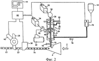
фиг.2 схематично иллюстрирует радиальную инжекцию добавки из твердых частиц в производстве стержня сигаретного фильтра согласно настоящему изобретению;2 schematically illustrates the radial injection of a particulate additive in the manufacture of a cigarette filter rod according to the present invention;
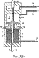
фиг.3(а) и фиг.3(b) более подробно схематически изображают вариант выполнения инжекционного приспособления для использования согласно изобретению, которое представлено на фиг.2;figure 3 (a) and figure 3 (b) in more detail schematically depict an embodiment of an injection device for use according to the invention, which is presented in figure 2;
фиг.4 схематически изображает варианты расположения включений добавок из твердых частиц в кратной длине фильтровых стержней согласно изобретению.figure 4 schematically depicts the location of inclusions of additives from solid particles in multiple lengths of filter rods according to the invention.
В обычной установке, изображенной на фиг.1, непрерывный жгут 2 из пластифицированного ацетилцеллюлозного волокна, который прошел обычные стадии предварительной обработки (не проиллюстрированы), обжимается воронками 27, 28, принимая стержневую форму по мере его продвижения вперед к аппарату 55 для изготовления фильтров, который образует из него непрерывный фильтровой стержень 57. Обертку 52 фильтра, движущуюся от подающей бобины 50, и жгут 2 протягивают через аппарат 55 по конвейеру 54, кроме того, при помощи конвейера 54 обертку 52 оборачивают вокруг стержня по мере его формования и закрепляются внахлестку клеевым швом. Стержень 57 сходит с конвейера 54 при помощи роликов 58, 59 в ножевое устройство 60, которое разрезает полученный стержень на отрезки 61 конечной длины.In the conventional apparatus shown in FIG. 1, a continuous bundle of plasticized cellulose acetate fiber 2, which has undergone the usual pretreatment steps (not illustrated), is crimped by
Обжимающие или уплотняющие приспособления 27, 28, представленные на фиг.1, можно было бы заменить единичной направляющей воронкой или подобным ей приспособлением. Такая единичная направляющая воронка 4 представлена на фиг.2, где номером 2 позиции обозначена подача жгута, как на фиг.1, но для ясности описания аппарат для изготовления фильтров не показан. На фиг.2 угольные гранулы 6 из расходного резервуара 8 порциями радиально вводятся к уплотняющемуся жгуту, находящемуся в воронке 4, через инжекторный цилиндр 10 при помощи инжекционного механизма 12, изображенного более подробно на фиг.3. Угольные гранулы сжатым воздухом перемещаются вдоль инжекторного цилиндра 10 и выходят из него с образованием включений 14, заделанных внутри непрерывно выпускаемого фильтрового стержня 57 и вытянутых вдоль него; несмотря на то что включения 14 изображены на фиг.2, в действительности они не видны в стержне. Подача угля в направлении 16 к резервуару 8 поддерживается под давлением сжатого воздуха из основного бака 18. Генератор 74 воздушного импульса, управляемый электродвигателем 34, получает воздух, находящийся под высоким давлением, от компрессора 22 и направляет часто повторяющиеся импульсы воздуха высокого давления к инжекционному механизму 12 в элемент, обозначенный на чертеже номером 24 позиции, чтобы соответственно вновь открыть клапан механизма 12, причем в промежутке между указанными импульсами давления клапан закрыт благодаря постоянному запирающему давлению воздуха, который поступает через впуск, обозначенный на чертеже номером 26 позиции. Таким образом, в процессе работы клапан очень быстро движется назад и вперед, многократно закрываясь и вновь открываясь. В то время когда клапан на мгновение откроется в местоположении, обозначенном на чертеже номером 46 позиции, и до тех пор, пока вскоре после этого он не закроется, угольные гранулы поступают в цилиндр 10 из резервуара 8; поступающие частицы сразу же быстро и разрозненно переносятся вдоль цилиндра 10 и высокоскоростным потоком нагнетаемого или транспортирующего воздуха (например, со скоростью 100-200 м/с или более), который постоянно проходит к цилиндру 10 из элемента, обозначенного на чертеже номером 20 позиции, вводятся радиально в уплотняющийся жгут, и по сути мгновенное перемещение и инжекция поступающих гранул продолжается до тех пор, пока клапан не закроется, чтобы на мгновение остановить подачу гранул; таким образом, угольные гранулы периодически вводятся радиально в проходящий жгут, образуя расположенные на расстоянии друг от друга аддитивные включения 14 в готовом фильтровом стержне; количество жгута, пропускаемого через установку, а также скорость и синхронность пневматической инжекции таковы, что во время каждой инжекции жгут перемещается вперед лишь на короткое расстояние, способствуя образованию готового стержня с включениями гранул, расположенными на точно определенном расстоянии. Ход или шаг открывания клапана инжекционного механизма 12 ограничен стопором 28, положение которого определяется кулачковым упором 33, настраиваемым электродвигателем 32, который управляется регулятором 76 скорости потока. Ножевое устройство 36 разрезает непрерывно выпускаемый стержень 57 на отрезки конечной длины, как показано номером 61 позиции, причем обычно они являются целым кратным (например 2- или 4- или 6-кратными) длине конечных единичных фильтров. Ножевое устройство 36 при помощи датчика 38 инфракрасного излучения, датчика 40 положения и устройства 42 управления вместе со средствами 44 взаимодействия пользователя синхронизировано с подачей жгута и управляет синхронной работой инжекционного механизма, чтобы обеспечить разрезание только между включениями, а не через них.Compression or
Даже если транспортирующий воздух, перемещающийся из элемента, обозначенного номером 20 позиции, поступает в воронку 4, его можно выпустить из фильтрующего материала до того, как последний окончательно сформуется в стержень; это можно выполнить, например, при помощи отверстия (не показано), проходящего сквозь стенку воронки 4. Дополнительно или вместо этого транспортирующий газ можно выпустить или осуществить его вытяжку в сторону от цилиндра 10 между отверстием клапана 46 и отверстием для выпуска инжекционных гранул. Соответственно, стрелка 19 обозначает данное дополнительное отведение или вытяжку газа за пределы уплотняющегося фильтрующего материала и воронки 4; этот процесс можно было бы выполнить при помощи выпускного отверстия или отверстий (не показаны), проходящих через стенку канала 10, либо через трубопровод (не показан), соединяющий внутреннее пространство канала 10 с источником вакуума; в последнем случае объемная скорость вытекающего потока может быть довольно высокой (например, больше чем объемная скорость потока, поступающего от элемента, обозначенного номером 20 позиции) для того, чтобы удалить лишние и мелкие частицы угля, но без чрезмерного влияния на инжекцию гранул большего размера, предназначенных для создания включения.Even if the transporting air moving from the element indicated by the
Инжекционное устройство 12, представленное на фиг.2, изображено более отчетливо на фиг.3(а) и 3(b), при этом клапан 13, 48 устройства показан соответственно открытым и закрытым в местоположении, обозначенном номером 46 позиции. На фиг.3(а) изображены угольные гранулы, поступающие в инжекторный цилиндр 10 через отверстие клапана 13, 48, находящееся внутри резервуара 8 в местоположении, обозначенном номером 46 позиции (смотри также фиг.2). Показано, что импульс воздуха высокого давления через вход 24 действует на поршень 48 клапана 13, толкая его обратно в камеру 70 пневматического амортизатора против запирающего давления воздуха, который поступает через впуск, обозначенный на чертеже номером 26 позиции, на мгновение открывая клапан в местоположении, обозначенном номером 46 позиции, в пределах, установленных ограничителем 28, пропуская угольные гранулы в цилиндр 10. На фиг.3(а) показано, что гранулы 6 распределены в сравнительно рассеянном потоке благодаря быстрому их удалению сжатым воздухом от впускного отверстия 46 клапана. Затем, как показано на фиг.3(b), в момент прекращения подачи импульса воздуха высокого давления через вход 24 запирающее давление воздуха, который поступает через впуск, обозначенный на чертеже номером 26 позиции, закрывает клапан, при этом воздух выходит через выход 72, а углеродные гранулы уносятся и радиально вводятся в уплотняющийся жгут через цилиндр 10 путем постоянной подачи воздуха, нагнетаемого из трубы 20. На фиг.3(b) показано незначительное количество гранул 6, которые последними попали в канал 10 непосредственно перед полным закрытием клапана в положении, обозначенном на чертеже номером 46 позиции. Нужно подчеркнуть, что изображение гранул 6 в канале 10, представленное на фиг.3(а) и 3(b), является чисто схематическим.The
Положение регулируемого ограничителя 28 определяет максимальный размер впускного отверстия 46 клапана; таким образом, для заданных рабочих параметров (давление в резервуаре, скорость перемещения клапана и время, в течение которого клапан полностью открыт) размер готового включения легко регулируется настройкой ограничителя 28.The position of the
В варианте выполнения и его модификациях, описанных выше со ссылкой на чертежи, цилиндр 10 проходит радиально оси прохода фильтрующего материала, но альтернативно цилиндр может и не быть перпендикулярным оси, например, может проходить наискось сквозь открытое пространство перед обжимным приспособлением внутрь уплотняющегося жгута.In the embodiment and its modifications described above with reference to the drawings, the
Можно получить различные образцы аддитивных включений в выпускаемом стержне путем регулирования последовательности импульсов воздуха через впуск 24 и, следовательно, последовательности открытия и закрытия клапана инжекционного механизма. На фиг.4 изображены три варианта расположения аддитивных включений в фильтровых стержнях согласно настоящему изобретению. Изображенные отрезки стержня четырехкратной длины, предназначенные для производства сигарет с фильтром, как правило, сначала разрезаются по линии В, чтобы получить два отрезка стержня двукратной длины; затем к каждому отрезку стержня двукратной длины прикрепляют два отрезка табачного стержня, по одному с каждого конца, после чего следует разрезание по линии А, чтобы получить две сигареты с фильтром. В варианте (а) включения 14, целиком находящиеся в стержне, расположены вдоль него одинаковым образом и на равном расстоянии, и в конечном единичном фильтре, входящем в сигарету с фильтром, включение 14 должно быть расположено по центру. В варианте (b) клапан инжекционного механизма работает в режиме варьируемого закрытия и получения широкого интервала между чередующимися включениями 14, а первоначальное отрезание отрезка стержня кратной длины от непрерывно выпускаемого изделия является таковым, что в сигарете с фильтром, произведенной вышеописанным способом, аддитивное включение единичного фильтра смещено к концу, находящемуся ближе ко рту курильщика. Предпочтительным является вариант (с), в котором непрерывно выпускаемый стержень имеет такой же образец включения, как в варианте (b), но первоначальное отрезание с целью получения отрезка стержня кратной длины таково, что аддитивное включение 14 конечного единичного фильтра смещено по направлению к табачному концу и удалено от рта курильщика; это уменьшает или исключает риск нагара, портящего внешний вид и вкусовые ощущения от сигареты с фильтром. Основа фильтрующего материала предпочтительных фильтровых стержней изобретения, которые проиллюстрированы, не содержит случайно инжектированных частиц, кроме того, и основа, и аддитивные включения по сути свободны от пыли и мелких частиц примесей. Изображение аддитивных включений на фиг.4 является схематичным; в действительности каждое включение предпочтительно имеет более изогнутую поверхность, как правило, в форме эллипса или мяча для игры в регби.You can get various samples of additive inclusions in the produced rod by regulating the sequence of pulses of air through the
Благодаря предложенным способу и устройству можно выпускать комбинированные фильтры, содержащие добавки, имеющие обычный размер, содержание угля и рабочие характеристики. Для примера, фильтры конечного изделия могут иметь стандартную длину окружности (например, 25 мм) и длину (например, до 27 или 25 мм), а также иметь стандартное содержание угля, примерно 15-35 мг или даже большее, вплоть до 60 мг; для более длинных мундштуков возможно большее содержание угля. Фильтрующие показатели фильтров аналогичны показателям обычных двойных фильтров, имеющих такое же содержание угля. Каждое отдельное аддитивное включение, находящееся в отрезке стержня длиной от 25 мм до 35 мм, может иметь длину, например, от 10 мм до 18 мм и диаметр от 3 мм до 4 мм, который может немного уменьшаться по направлению к каждому концу. Однопроходный непрерывный способ и устройство изобретения могут эффективно функционировать при эксплуатационной скорости (например, свыше 200 м/мин); поперечная, например радиальная пневматическая, подача и инжекция добавки из твердых частиц сохраняет интервал и максимизируют точное определение местоположения и локализацию включений, уменьшая или исключая таким образом брак или нестабильное качество продукции, обусловленное рассеиванием добавки или слиянием включений; это происходит вследствие того, что поперечная траектория пневматического перемещения может быть короче - например, в представленном приспособлении расстояние от впускного отверстия 46 клапана до точки инжекции может составлять всего лишь около 135 мм, и возможны даже более короткие расстояния.Thanks to the proposed method and device, it is possible to produce combined filters containing additives having a normal size, coal content and performance. For example, the filters of the final product can have a standard circumference (for example, 25 mm) and a length (for example, up to 27 or 25 mm), and also have a standard coal content of about 15-35 mg or even more, up to 60 mg; for longer mouthpieces, a higher coal content is possible. The filtering performance of filters is similar to that of conventional dual filters having the same coal content. Each individual additive inclusion located in a segment of the rod with a length of 25 mm to 35 mm may have a length of, for example, from 10 mm to 18 mm and a diameter of 3 mm to 4 mm, which may slightly decrease towards each end. The one-pass continuous method and device of the invention can function efficiently at a production speed (for example, above 200 m / min); transverse, for example, radial pneumatic, feeding and injection of the additive from particulate matter maintains the interval and maximizes the exact location and localization of inclusions, thereby reducing or eliminating defective or unstable product quality due to dispersion of the additive or merging of inclusions; this is due to the fact that the lateral path of pneumatic movement can be shorter - for example, in the device shown, the distance from the
Устройство для пневматической инжекции, используемое в настоящем способе и устройстве, является преимущественным само по себе, будучи компактным и эффективным, а также имеет возможность быстрой подгонки в большинстве или во всех обычных машинах, выпускающих сигареты с фильтром. Соответственно, такая подгонка к обычному оборудованию требует всего лишь незначительной модификации или замены обжимающей воронки, чтобы приспособить боковой инжекторный цилиндр или канал и/или при возможности создать дополнительные отверстия для выпуска сжатого инжекционного газа; и даже такие незначительные модификации могут не понадобиться, если инжекторный цилиндр проходит поперек или аксиально открытому входному отверстию обжимного приспособления и через него, и/или существует условие для бокового выпуска транспортирующего газа за пределы обжимного приспособления перед отверстием инжекторного цилиндра для выпуска частиц. Следовательно, изобретение также предлагает устройство, предназначенное для введения добавки из твердых частиц в непрерывную последовательность материала, фильтрующего табачный дым, причем устройство содержит инжекторный канал, входящий (и предпочтительно поперек) в данный материал и имеющий клапан, предназначенный для периодической подачи добавки из твердых частиц в канал, приспособление, предназначенное для повторяющегося открытия и закрытия клапана с обеспечением поступления добавки из твердых частиц в канал, когда клапан открыт, и приспособление для впуска постоянного потока высокоскоростного транспортирующего газа в инжекторный канал, чтобы транспортировать указанную поданную добавку из твердых частиц вдоль канала для периодической пневматической инжекции в данный материал. Клапан предпочтительно такой же, как клапан, изображенный на фиг.2 и фиг.3, или ему подобный, который является средством, предназначенным для движения назад и вперед между открытым и закрытым положениями. Добавка твердых частиц подается под давлением сжатого воздуха предпочтительно из резервуара, предназначенного для ее приема и хранения, а более предпочтительно, чтобы инжекторный канал проходил через резервуар. Для вышеуказанных целей перед отверстием канала для выпуска частиц устройство может иметь вышеописанное приспособление, предназначенное для выпуска или вытяжки транспортирующего газа.The pneumatic injection device used in the present method and device is advantageous in itself, being compact and efficient, and also has the ability to quickly fit in most or all conventional cigarette filter making machines. Accordingly, such a fit to conventional equipment requires only a slight modification or replacement of the compression funnel in order to accommodate the side injection cylinder or channel and / or, if possible, create additional openings for the release of compressed injection gas; and even such minor modifications may not be necessary if the injector cylinder extends across or axially open the inlet of the crimping device and through it, and / or there is a condition for lateral discharge of the conveying gas outside the crimping device in front of the opening of the injection cylinder for particle discharge. Therefore, the invention also provides a device for introducing an additive of particulate matter into a continuous sequence of tobacco smoke filtering material, the device comprising an injection channel extending (and preferably transversely) into the material and having a valve for periodically supplying the additive of particulate matter in the channel, a device designed to repeatedly open and close the valve with the addition of particulate matter to the channel when the valve is open and a device for admitting a constant flow of high-speed carrier gas into the injection channel to transport said supplied particulate additive along the channel for periodic pneumatic injection into the material. The valve is preferably the same as the valve depicted in FIG. 2 and FIG. 3, or the like, which is a means for moving back and forth between open and closed positions. The particulate additive is supplied under pressure from compressed air, preferably from a reservoir for receiving and storing it, and more preferably, the injection channel passes through the reservoir. For the above purposes, in front of the opening of the channel for the release of particles, the device may have the above-described device, designed to release or exhaust the transporting gas.
Claims (25)
Applications Claiming Priority (2)
| Application Number | Priority Date | Filing Date | Title |
|---|---|---|---|
| GB0426615.1 | 2004-12-03 | ||
| GBGB0426615.1A GB0426615D0 (en) | 2004-12-03 | 2004-12-03 | Tobacco smoke filter |
Publications (2)
| Publication Number | Publication Date |
|---|---|
| RU2007120343A RU2007120343A (en) | 2009-01-20 |
| RU2391883C2 true RU2391883C2 (en) | 2010-06-20 |
Family
ID=34044040
Family Applications (1)
| Application Number | Title | Priority Date | Filing Date |
|---|---|---|---|
| RU2007120343/12A RU2391883C2 (en) | 2004-12-03 | 2005-12-05 | Production of filters for tobacco smoke |
Country Status (15)
| Country | Link |
|---|---|
| US (1) | US8083658B2 (en) |
| EP (2) | EP2308329B1 (en) |
| JP (1) | JP4933444B2 (en) |
| KR (1) | KR101335410B1 (en) |
| CN (1) | CN101090646B (en) |
| AT (1) | ATE511361T1 (en) |
| BR (1) | BRPI0518273B1 (en) |
| CA (1) | CA2589741C (en) |
| GB (1) | GB0426615D0 (en) |
| HU (1) | HUE035802T2 (en) |
| LT (1) | LT2308329T (en) |
| PL (2) | PL2308329T3 (en) |
| RU (1) | RU2391883C2 (en) |
| UA (1) | UA91989C2 (en) |
| WO (1) | WO2006059134A1 (en) |
Cited By (1)
| Publication number | Priority date | Publication date | Assignee | Title |
|---|---|---|---|---|
| RU2776285C2 (en) * | 2018-02-15 | 2022-07-18 | Филип Моррис Продактс С.А. | Method and device for bending material canvas |
Families Citing this family (32)
| Publication number | Priority date | Publication date | Assignee | Title |
|---|---|---|---|---|
| US7479098B2 (en) | 2005-09-23 | 2009-01-20 | R. J. Reynolds Tobacco Company | Equipment for insertion of objects into smoking articles |
| US7740019B2 (en) | 2006-08-02 | 2010-06-22 | R.J. Reynolds Tobacco Company, Inc. | Equipment and associated method for insertion of material into cigarette filters |
| US7972254B2 (en) * | 2007-06-11 | 2011-07-05 | R.J. Reynolds Tobacco Company | Apparatus for inserting objects into a filter component of a smoking article, and associated method |
| DE102007057396A1 (en) * | 2007-11-27 | 2009-05-28 | Hauni Maschinenbau Ag | Device for processing at least two filter tows |
| WO2009098462A1 (en) * | 2008-02-07 | 2009-08-13 | Filtrona International Limited | Tobacco smoke filter |
| US8079369B2 (en) | 2008-05-21 | 2011-12-20 | R.J. Reynolds Tobacco Company | Method of forming a cigarette filter rod member |
| US8375958B2 (en) * | 2008-05-21 | 2013-02-19 | R.J. Reynolds Tobacco Company | Cigarette filter comprising a carbonaceous fiber |
| DE102008024553A1 (en) * | 2008-05-21 | 2009-12-03 | Hauni Maschinenbau Aktiengesellschaft | Device for introducing additives into a strand provided for the production of a smoking article and already round-shaped |
| US8613284B2 (en) * | 2008-05-21 | 2013-12-24 | R.J. Reynolds Tobacco Company | Cigarette filter comprising a degradable fiber |
| ES2420685T5 (en) * | 2008-05-21 | 2017-02-10 | R.J. Reynolds Tobacco Company | Apparatus and associated method for forming a filter component of a smoking article and smoking articles manufactured therefrom |
| ZA200901679B (en) * | 2009-03-09 | 2015-08-26 | Tobacco Res And Development Institute (Pty) Ltd | Apparatus for introducing objects into filter rod material |
| GB0906187D0 (en) | 2009-04-09 | 2009-05-20 | British American Tobacco Co | Smoking article filter |
| GB0906192D0 (en) * | 2009-04-09 | 2009-05-20 | British American Tobacco Co | Apparatus |
| DE102009017963A1 (en) | 2009-04-21 | 2010-10-28 | Hauni Maschinenbau Ag | Capsule monitoring and capsule position control in filters of the tobacco processing industry |
| GB0916539D0 (en) * | 2009-09-21 | 2009-10-28 | British American Tobacco Co | Method and apparatus for introducing objects into filter rod material |
| GB201004976D0 (en) * | 2010-03-24 | 2010-05-12 | Filtrona Int Ltd | Tobacco smoke filter |
| LT2579736T (en) | 2010-06-10 | 2019-04-10 | Essentra Filter Products Development Co. Pte. Ltd. | Tobacco smoke filter |
| GB201016387D0 (en) * | 2010-09-29 | 2010-11-10 | Filtrona Int Ltd | Tobacco smoke filter |
| ZA201008663B (en) * | 2010-12-01 | 2014-08-27 | Tobacco Res And Dev Inst (Pty) Ltd | Feed mechanism |
| GB201104475D0 (en) | 2011-03-16 | 2011-04-27 | Filtrona Filter Prod Dev Co | Tobacco smoke filter |
| US9055768B2 (en) | 2011-03-25 | 2015-06-16 | Hauni Maschinenbau Ag | High speed object inserter and related methods |
| US9232820B2 (en) | 2011-03-25 | 2016-01-12 | Hauni Maschinenbau Ag | High speed object inserter and related methods |
| WO2013004994A1 (en) * | 2011-07-07 | 2013-01-10 | Filtrona Filter Products Development Co.Pte.Ltd | Tobacco smoke filter and method of production |
| US20130085052A1 (en) * | 2011-09-29 | 2013-04-04 | R. J. Reynolds Tobacco Company | Apparatus for Inserting Microcapsule Objects into a Filter Element of a Smoking Article, and Associated Method |
| GB201219540D0 (en) | 2012-10-31 | 2012-12-12 | British American Tobacco Co | A filter for a smoking article |
| RU2015125461A (en) * | 2012-11-29 | 2017-01-10 | Филип Моррис Продактс С.А. | METHOD AND DEVICE FOR INTRODUCING DOSED NUMBER OF PARTICLES INTO CONTINUOUS MATERIAL FLOW |
| CN103653243B (en) * | 2013-12-04 | 2015-08-19 | 上海烟草集团有限责任公司 | The filter-stick forming device of multi-functional adding material |
| GB201507269D0 (en) * | 2015-04-29 | 2015-06-10 | British American Tobacco Co | Flavouring component and apparatus and method for manufacturing a flavouring component |
| JP6789983B2 (en) * | 2015-05-21 | 2020-11-25 | フィリップ・モーリス・プロダクツ・ソシエテ・アノニム | Induction heating tobacco rod manufacturing method |
| US11291241B2 (en) | 2015-11-30 | 2022-04-05 | Philip Morris Products S.A. | Smoking article comprising a filter with enhanced flavourant release |
| KR20220146185A (en) * | 2021-04-23 | 2022-11-01 | 주식회사 케이티앤지 | Filter, an aerosol-generating article comrising the same, and a method of manufacturing the filter |
| KR102506378B1 (en) | 2022-08-24 | 2023-03-06 | 태영산업 주식회사 | method and apparatus for manufacturing paper cigarette filter |
Family Cites Families (27)
| Publication number | Priority date | Publication date | Assignee | Title |
|---|---|---|---|---|
| GB1106931A (en) * | 1963-10-04 | 1968-03-20 | Molins Organization Ltd | Improvements in apparatus for producing composite filter plugs |
| GB1246627A (en) * | 1967-09-15 | 1971-09-15 | Molins Machine Co Ltd | Apparatus for producing composite filters for cigarettes |
| DE1912773A1 (en) * | 1969-03-13 | 1970-10-01 | Freudenberg Carl Fa | Device for applying locally limited amounts of binder to webs |
| US3844200A (en) * | 1973-05-07 | 1974-10-29 | Brown & Williamson Tobacco | Continuous manufacture of a multiple filter rod having spaced pockets containing particulate material |
| US4016830A (en) * | 1975-07-16 | 1977-04-12 | Brown & Williamson Tobacco Corporation | Apparatus for dispensing spaced deposits of particulate material |
| US4026306A (en) * | 1975-11-06 | 1977-05-31 | American Filtrona Corporation | Tobacco smoke filter |
| CH613850A5 (en) * | 1976-11-26 | 1979-10-31 | Baumgartner Papiers Sa | |
| US4184412A (en) * | 1977-03-18 | 1980-01-22 | Liggett Group Inc. | Pocket-type charcoal filter and cigarette made therewith |
| GB1601221A (en) * | 1977-03-18 | 1981-10-28 | Liggett Group Inc | Filter cigarette |
| GB1585761A (en) | 1977-06-01 | 1981-03-11 | Cigarette Components Ltd | Tobacco smoke filters |
| US4355995A (en) * | 1979-03-27 | 1982-10-26 | American Filtrona Corporation | Tobacco smoke filter providing tobacco flavor enrichment, and method for producing same |
| US4285677A (en) | 1979-09-07 | 1981-08-25 | Daicel Ltd. | Method and apparatus for the manufacture of cigarette filters containing particulate material |
| US4549875A (en) | 1983-06-02 | 1985-10-29 | R. J. Reynolds Tobacco Co. | Manufacture of tobacco smoke filters |
| CH669309A5 (en) * | 1985-08-26 | 1989-03-15 | Baumgartner Papiers Sa | |
| US4715390A (en) * | 1985-11-19 | 1987-12-29 | Philip Morris Incorporated | Matrix entrapment of flavorings for smoking articles |
| US5271419A (en) * | 1989-09-29 | 1993-12-21 | R. J. Reynolds Tobacco Company | Cigarette |
| CN1056910A (en) * | 1990-05-19 | 1991-12-11 | 董致温 | A kind of technology of separating and filtering mouth stub principal component |
| DE4109603A1 (en) * | 1991-03-23 | 1992-09-24 | Hauni Werke Koerber & Co Kg | METHOD AND DEVICE FOR PRODUCING FILTER RODS FOR CIGARETTES |
| KR950010498Y1 (en) * | 1993-07-16 | 1995-12-18 | 동양물산기업주식회사 | Apparatus for producing filter of tobacco |
| EP1156721B1 (en) | 1999-03-02 | 2010-12-22 | Philip Morris Products S.A. | Method and apparatus for producing particle bearing filter rod |
| DE19959034B4 (en) | 1999-12-08 | 2008-01-17 | Hauni Maschinenbau Ag | Method and device for feeding a preferably liquid additive to a moving web |
| DE10010176B4 (en) * | 2000-03-02 | 2005-10-06 | Reemtsma Cigarettenfabriken Gmbh | Method and device for producing an additive-treated filter cable |
| US6537186B1 (en) * | 2000-07-05 | 2003-03-25 | Baumgartner Papiers S.A. | Process and apparatus for high-speed filling of composite cigarette filters |
| KR20040017356A (en) * | 2001-08-02 | 2004-02-26 | 니뽄 다바코 산교 가부시키가이샤 | Filter for cigarette |
| BR0212003B1 (en) * | 2001-08-17 | 2013-11-12 | APPARATUS AND PROCESS FOR FILLING SPACES BETWEEN YOURS WITH PRIVATE MATERIAL AND APPARATUS, PROCESS AND SYSTEM FOR FILLING AT LEAST ONE CAVITY IN A ITEM WITH GRANULAR OR PARTICULAR MATERIAL | |
| US20030159703A1 (en) * | 2002-02-22 | 2003-08-28 | Zuyin Yang | Flavored carbon useful as filtering material of smoking article |
| US20040231684A1 (en) * | 2003-05-20 | 2004-11-25 | Zawadzki Michael A. | Smoking article and smoking article filter |
-
2004
- 2004-12-03 GB GBGB0426615.1A patent/GB0426615D0/en not_active Ceased
-
2005
- 2005-12-05 HU HUE10075418A patent/HUE035802T2/en unknown
- 2005-12-05 CN CN2005800413997A patent/CN101090646B/en active Active
- 2005-12-05 PL PL10075418T patent/PL2308329T3/en unknown
- 2005-12-05 WO PCT/GB2005/004644 patent/WO2006059134A1/en active Application Filing
- 2005-12-05 CA CA2589741A patent/CA2589741C/en active Active
- 2005-12-05 EP EP10075418.3A patent/EP2308329B1/en active Active
- 2005-12-05 LT LTEP10075418.3T patent/LT2308329T/en unknown
- 2005-12-05 UA UAA200706104A patent/UA91989C2/en unknown
- 2005-12-05 PL PL05814073T patent/PL1827144T3/en unknown
- 2005-12-05 EP EP05814073A patent/EP1827144B1/en active Active
- 2005-12-05 RU RU2007120343/12A patent/RU2391883C2/en active
- 2005-12-05 AT AT05814073T patent/ATE511361T1/en not_active IP Right Cessation
- 2005-12-05 BR BRPI0518273A patent/BRPI0518273B1/en active IP Right Grant
- 2005-12-05 US US11/792,212 patent/US8083658B2/en active Active
- 2005-12-05 KR KR1020077012301A patent/KR101335410B1/en active IP Right Grant
- 2005-12-05 JP JP2007543922A patent/JP4933444B2/en active Active
Cited By (2)
| Publication number | Priority date | Publication date | Assignee | Title |
|---|---|---|---|---|
| RU2776285C2 (en) * | 2018-02-15 | 2022-07-18 | Филип Моррис Продактс С.А. | Method and device for bending material canvas |
| RU2810767C2 (en) * | 2019-03-28 | 2023-12-28 | Филип Моррис Продактс С.А. | Moulding installation for moulding continuous tubular rod, production line for producing continuous tubular rod and method for moulding continuous tubular rod from continuous rod material |
Also Published As
| Publication number | Publication date |
|---|---|
| LT2308329T (en) | 2018-01-10 |
| GB0426615D0 (en) | 2005-01-05 |
| BRPI0518273B1 (en) | 2016-07-05 |
| JP2008521429A (en) | 2008-06-26 |
| US20080190439A1 (en) | 2008-08-14 |
| WO2006059134A1 (en) | 2006-06-08 |
| CN101090646B (en) | 2011-08-03 |
| RU2007120343A (en) | 2009-01-20 |
| ATE511361T1 (en) | 2011-06-15 |
| CA2589741C (en) | 2010-09-28 |
| CA2589741A1 (en) | 2006-06-08 |
| EP1827144B1 (en) | 2011-06-01 |
| PL2308329T3 (en) | 2018-05-30 |
| EP1827144A1 (en) | 2007-09-05 |
| PL1827144T3 (en) | 2011-10-31 |
| US8083658B2 (en) | 2011-12-27 |
| HUE035802T2 (en) | 2018-05-28 |
| UA91989C2 (en) | 2010-09-27 |
| KR20070087580A (en) | 2007-08-28 |
| EP2308329A1 (en) | 2011-04-13 |
| BRPI0518273A2 (en) | 2008-11-11 |
| JP4933444B2 (en) | 2012-05-16 |
| EP2308329B1 (en) | 2017-11-22 |
| CN101090646A (en) | 2007-12-19 |
| KR101335410B1 (en) | 2013-12-02 |
Similar Documents
| Publication | Publication Date | Title |
|---|---|---|
| RU2391883C2 (en) | Production of filters for tobacco smoke | |
| CN1112863C (en) | Cigarette and method of manufacturing cigarette for electrical smoking system | |
| JP6139915B2 (en) | Method and apparatus for manufacturing paperless filter rods for smoking articles | |
| US3672373A (en) | Method and means for regulating the operation of apparatus for the production and processing of cigarettes or the like | |
| CN108348000B (en) | Filter manufacturing equipment | |
| PL1763306T3 (en) | Apparatus and method for the production of composite cigarette filters | |
| US6723033B1 (en) | Method and apparatus for producing particle bearing filter rod | |
| CN102149293A (en) | Fluid encapsulation | |
| JP2015503344A (en) | Method of filter assembly for smoking articles | |
| US4184412A (en) | Pocket-type charcoal filter and cigarette made therewith | |
| NO179471B (en) | Process and system for making block bodies from dissolved material such as peat | |
| CN102657379A (en) | Forming method and device of filter sticks of cigarettes | |
| HU181852B (en) | Method and apparatus for continuous producing from-keeping rod-shaped members consist of long-fibred and/or fibrous material particularly cigarette filter inserts | |
| WO2014135913A1 (en) | Method and apparatus for the recovery of tobacco from cigarettes with filter | |
| IE46164B1 (en) | Improvements ind machines for making cigarette filters | |
| JP4532254B2 (en) | Apparatus for forming a continuous mat-like compact of tobacco | |
| MX2007006658A (en) | Tobacco smoke filter production | |
| WO2017187502A1 (en) | Rod product production device | |
| PL358113A1 (en) | Apparatus for preparing at least one web of filter material for tobacco processing industry and method of preparing at least one wqeb of ilter material for tobacco processing industry | |
| RU2714654C2 (en) | Method and apparatus for introducing elongate objects forming longitudinal axis into continuous stream of material | |
| PL1488712T3 (en) | Sifting means for sifting a product stream within a distributor apparatus |