RU2390954C2 - Interference control in wireless communication system - Google Patents
Interference control in wireless communication system Download PDFInfo
- Publication number
- RU2390954C2 RU2390954C2 RU2007138022/09A RU2007138022A RU2390954C2 RU 2390954 C2 RU2390954 C2 RU 2390954C2 RU 2007138022/09 A RU2007138022/09 A RU 2007138022/09A RU 2007138022 A RU2007138022 A RU 2007138022A RU 2390954 C2 RU2390954 C2 RU 2390954C2
- Authority
- RU
- Russia
- Prior art keywords
- sector
- interference
- terminals
- neighboring
- terminal
- Prior art date
Links
Images


Classifications
-
- H—ELECTRICITY
- H04—ELECTRIC COMMUNICATION TECHNIQUE
- H04W—WIRELESS COMMUNICATION NETWORKS
- H04W52/00—Power management, e.g. TPC [Transmission Power Control], power saving or power classes
- H04W52/04—TPC
- H04W52/18—TPC being performed according to specific parameters
- H04W52/24—TPC being performed according to specific parameters using SIR [Signal to Interference Ratio] or other wireless path parameters
-
- H—ELECTRICITY
- H04—ELECTRIC COMMUNICATION TECHNIQUE
- H04L—TRANSMISSION OF DIGITAL INFORMATION, e.g. TELEGRAPHIC COMMUNICATION
- H04L1/00—Arrangements for detecting or preventing errors in the information received
-
- H—ELECTRICITY
- H04—ELECTRIC COMMUNICATION TECHNIQUE
- H04W—WIRELESS COMMUNICATION NETWORKS
- H04W28/00—Network traffic management; Network resource management
- H04W28/02—Traffic management, e.g. flow control or congestion control
- H04W28/04—Error control
-
- H—ELECTRICITY
- H04—ELECTRIC COMMUNICATION TECHNIQUE
- H04W—WIRELESS COMMUNICATION NETWORKS
- H04W28/00—Network traffic management; Network resource management
- H04W28/16—Central resource management; Negotiation of resources or communication parameters, e.g. negotiating bandwidth or QoS [Quality of Service]
- H04W28/24—Negotiating SLA [Service Level Agreement]; Negotiating QoS [Quality of Service]
-
- H—ELECTRICITY
- H04—ELECTRIC COMMUNICATION TECHNIQUE
- H04W—WIRELESS COMMUNICATION NETWORKS
- H04W52/00—Power management, e.g. TPC [Transmission Power Control], power saving or power classes
- H04W52/04—TPC
- H04W52/18—TPC being performed according to specific parameters
- H04W52/24—TPC being performed according to specific parameters using SIR [Signal to Interference Ratio] or other wireless path parameters
- H04W52/243—TPC being performed according to specific parameters using SIR [Signal to Interference Ratio] or other wireless path parameters taking into account interferences
- H04W52/244—Interferences in heterogeneous networks, e.g. among macro and femto or pico cells or other sector / system interference [OSI]
-
- H—ELECTRICITY
- H04—ELECTRIC COMMUNICATION TECHNIQUE
- H04W—WIRELESS COMMUNICATION NETWORKS
- H04W52/00—Power management, e.g. TPC [Transmission Power Control], power saving or power classes
- H04W52/04—TPC
- H04W52/18—TPC being performed according to specific parameters
- H04W52/26—TPC being performed according to specific parameters using transmission rate or quality of service QoS [Quality of Service]
- H04W52/265—TPC being performed according to specific parameters using transmission rate or quality of service QoS [Quality of Service] taking into account the quality of service QoS
-
- H—ELECTRICITY
- H04—ELECTRIC COMMUNICATION TECHNIQUE
- H04W—WIRELESS COMMUNICATION NETWORKS
- H04W72/00—Local resource management
- H04W72/50—Allocation or scheduling criteria for wireless resources
- H04W72/54—Allocation or scheduling criteria for wireless resources based on quality criteria
- H04W72/541—Allocation or scheduling criteria for wireless resources based on quality criteria using the level of interference
-
- H—ELECTRICITY
- H04—ELECTRIC COMMUNICATION TECHNIQUE
- H04B—TRANSMISSION
- H04B17/00—Monitoring; Testing
- H04B17/10—Monitoring; Testing of transmitters
-
- H—ELECTRICITY
- H04—ELECTRIC COMMUNICATION TECHNIQUE
- H04B—TRANSMISSION
- H04B17/00—Monitoring; Testing
- H04B17/30—Monitoring; Testing of propagation channels
- H04B17/309—Measuring or estimating channel quality parameters
- H04B17/345—Interference values
-
- H—ELECTRICITY
- H04—ELECTRIC COMMUNICATION TECHNIQUE
- H04W—WIRELESS COMMUNICATION NETWORKS
- H04W52/00—Power management, e.g. TPC [Transmission Power Control], power saving or power classes
- H04W52/04—TPC
- H04W52/06—TPC algorithms
- H04W52/14—Separate analysis of uplink or downlink
- H04W52/146—Uplink power control
-
- H—ELECTRICITY
- H04—ELECTRIC COMMUNICATION TECHNIQUE
- H04W—WIRELESS COMMUNICATION NETWORKS
- H04W52/00—Power management, e.g. TPC [Transmission Power Control], power saving or power classes
- H04W52/04—TPC
- H04W52/18—TPC being performed according to specific parameters
- H04W52/24—TPC being performed according to specific parameters using SIR [Signal to Interference Ratio] or other wireless path parameters
- H04W52/247—TPC being performed according to specific parameters using SIR [Signal to Interference Ratio] or other wireless path parameters where the output power of a terminal is based on a path parameter sent by another terminal
-
- H—ELECTRICITY
- H04—ELECTRIC COMMUNICATION TECHNIQUE
- H04W—WIRELESS COMMUNICATION NETWORKS
- H04W52/00—Power management, e.g. TPC [Transmission Power Control], power saving or power classes
- H04W52/04—TPC
- H04W52/30—TPC using constraints in the total amount of available transmission power
- H04W52/36—TPC using constraints in the total amount of available transmission power with a discrete range or set of values, e.g. step size, ramping or offsets
- H04W52/362—Aspects of the step size
-
- H—ELECTRICITY
- H04—ELECTRIC COMMUNICATION TECHNIQUE
- H04W—WIRELESS COMMUNICATION NETWORKS
- H04W92/00—Interfaces specially adapted for wireless communication networks
- H04W92/16—Interfaces between hierarchically similar devices
- H04W92/20—Interfaces between hierarchically similar devices between access points
Abstract
Description
Данная заявка является частичным продолжением патентной заявки США № 11/158,584, поданной 21 июня 2005 г., под названием "Interference Control In A Wireless Communication System" и переуступленной правопреемнику настоящей заявки, и включенной посредством ссылки в полном объеме.This application is a partial continuation of US patent application No. 11 / 158,584, filed June 21, 2005, under the name "Interference Control In A Wireless Communication System" and assigned to the assignee of this application, and incorporated by reference in full.
Область техники, к которой относится изобретениеFIELD OF THE INVENTION
Настоящее раскрытие относится, в целом, к области связи и, в частности, к управлению помехой в системе беспроводной связи.The present disclosure relates generally to the field of communications and, in particular, to interference management in a wireless communication system.
Описание уровня техникиDescription of the prior art
Система беспроводной связи с множественным доступом может одновременно осуществлять связь с множеством терминалов по прямой и обратной линиям связи. Прямая линия связи (или нисходящая линия связи) - это линия связи от базовых станций к терминалам, а обратная линия связи (или восходящая линия связи) - это линия связи от терминалов к базовым станциям. Множество терминалов могут одновременно передавать данные по обратной линии связи и/или принимать данные по прямой линии связи. Это часто достигается за счет мультиплексирования передач в каждой линии связи, ортогональных друг другу во временной, частотной и/или кодовой области.A multiple access wireless communication system can simultaneously communicate with multiple terminals on the forward and reverse links. The forward link (or downlink) is the communication line from the base stations to the terminals, and the reverse link (or uplink) is the communication line from the terminals to the base stations. Many terminals can simultaneously transmit data on the reverse link and / or receive data on the forward link. This is often achieved by multiplexing transmissions on each communication link orthogonal to each other in the time, frequency and / or code domain.
В обратной линии связи передачи от терминалов, осуществляющих связь с разными базовыми станциями, обычно не ортогональны друг другу. Поэтому каждый терминал может создавать помеху для других терминалов, осуществляющих связь с ближайшими базовыми станциями, а также может принимать помеху от этих других терминалов. Производительность каждого терминала снижается за счет помехи от других терминалов, осуществляющих связь с другими базовыми станциями.On the reverse link, transmissions from terminals communicating with different base stations are usually not orthogonal to each other. Therefore, each terminal may interfere with other terminals communicating with the nearest base stations, and may also receive interference from these other terminals. The performance of each terminal is reduced due to interference from other terminals communicating with other base stations.
Поэтому в технике существует необходимость в ослаблении помехи в системе беспроводной связи.Therefore, in the art there is a need to mitigate interference in a wireless communication system.
Сущность изобретенияSUMMARY OF THE INVENTION
Здесь описаны методы управления помехой, воспринимаемой каждым сектором из соседних секторов в системе беспроводной связи. Сектор m оценивает воспринимаемую помеху от терминалов в соседних секторах и получает оценку помехи или связанные измерения. Для сетевого управления помехой сектор m генерирует межсекторный (IS) отчет OSI на основании оценки помехи и отправляет отчет IS OSI в соседние секторы посредством проводного соединения, например транзитного соединения. Сектор m также принимает отчеты IS OSI из соседних секторов и регулирует передачи данных для терминалов в секторе m на основании принятых отчетов IS OSI. Сектор m может регулировать передачи данных путем (1) управления доступом новых терминалов в сектор m, (2) отмены назначения ранее допущенных терминалов, (3) диспетчеризации терминалов в секторе m таким образом, чтобы снизить помеху для соседних секторов, и/или (4) назначения терминалам в секторе m каналов трафика, которые обуславливают уменьшение помехи для соседних секторов.Methods for controlling interference perceived by each sector from neighboring sectors in a wireless communication system are described herein. Sector m evaluates the perceived interference from terminals in neighboring sectors and obtains an interference estimate or related measurements. For network interference control, sector m generates an intersectorial (IS) OSI report based on the interference estimate and sends an OSI IS report to neighboring sectors via a wired connection, such as a backhaul. Sector m also receives IS OSI reports from neighboring sectors and regulates data transmissions for terminals in sector m based on received IS OSI reports. Sector m can regulate data transfers by (1) controlling access of new terminals to sector m , (2) de-assigning previously allowed terminals, (3) scheduling terminals in sector m in such a way as to reduce interference for neighboring sectors, and / or (4 ) assignment of traffic channels to terminals in sector m , which cause interference reduction for neighboring sectors.
Различные аспекты и варианты осуществления изобретения более подробно описаны ниже.Various aspects and embodiments of the invention are described in more detail below.
Краткое описание чертежейBrief Description of the Drawings
Признаки и характер настоящего изобретения поясняются в подробном описании, приведенном ниже совместно с чертежами, на которых одинаковые ссылочные позиции обозначают соответствующие элементы.The features and nature of the present invention are explained in the detailed description below in conjunction with the drawings, in which like reference numerals indicate corresponding elements.
Фиг.1 - система связи, имеющая базовые станции и терминалы.Figure 1 - communication system having base stations and terminals.
Фиг.2 - процесс, осуществляемый одним сектором, для управления помехой.Figure 2 is a process carried out by one sector to control interference.
Фиг.3 - процесс, осуществляемый одним терминалом, для управления помехой.Figure 3 is a process carried out by a single terminal for interference control.
Фиг.4 - процесс регулировки передаваемой мощности детерминированным способом.Figure 4 - the process of adjusting the transmitted power in a deterministic way.
Фиг.5 - процесс регулировки передаваемой мощности вероятностным способом.5 is a process for adjusting transmitted power in a probabilistic manner.
Фиг.6 - механизм управления мощностью, пригодный для управления помехой.6 is a power control mechanism suitable for controlling interference.
Фиг.7 - блок-схема терминала и двух базовых станций.7 is a block diagram of a terminal and two base stations.
Фиг.8 - устройство, пригодное для управления помехой.8 is a device suitable for controlling interference.
Фиг.9 - устройство, пригодное для обеспечения управления помехой.Fig.9 is a device suitable for providing interference control.
Подробное описаниеDetailed description
Слово "иллюстративный" используется здесь в смысле "служащий примером, вариантом или иллюстрацией". Любой вариант осуществления, описанный здесь как "иллюстративный", не обязательно рассматривать как предпочтительный или имеющий преимущество над другими вариантами осуществления или структурами.The word "illustrative" is used here in the sense of "serving as an example, option, or illustration." Any embodiment described herein as “illustrative” is not necessarily considered to be preferred or having an advantage over other embodiments or structures.
На фиг.1 показана система беспроводной связи 100, имеющая множество базовых станций 110 и множество терминалов 120. Базовая станция, в общем случае, является фиксированной станцией, которая осуществляет связь с терминалами, и также может называться узлом доступа, узлом B, или каким-либо другим термином. Каждая базовая станция 110 обеспечивает покрытие связью для конкретной географической области 102a, 102b, 102c. Термин "сота" может относиться к базовой станции и/или ее зоне покрытия в зависимости от контекста использования термина. Для повышения емкости системы, зону покрытия базовой станции можно разделить на множество подобластей, например три подобласти 104a, 104b и 104c. Каждая подобласть обслуживается соответствующей базовой приемопередающей подсистемой (BTS). Термин "сектор" может относиться к BTS и/или ее зоне покрытия в зависимости от контекста использования термина. Для соты, разделенной на секторы, BTS для всех секторов этой соты обычно совмещены на базовой станции соты. Системный контроллер 130 подключен к базовым станциям 110 и обеспечивает координацию и контроль для этих базовых станций.1 shows a
Терминал может быть фиксированным или мобильным и также может называться мобильной станцией, беспроводным устройством, пользовательским оборудованием или каким-либо другим термином. Каждый терминал может осуществлять связь ни с одной, с одной или с множеством базовых станций в любой данный момент времени.A terminal may be fixed or mobile, and may also be called a mobile station, wireless device, user equipment, or some other terminology. Each terminal can communicate with any, with one or with many base stations at any given time.
Описанные здесь методы управления помехой можно использовать для систем с сотами, разделенными на секторы, и без разделения на секторы. В нижеследующем описании, термин "сектор" означает (1) традиционную BTS и/или ее зону покрытия для системы с сотами разделенными на секторы и (2) традиционную базовую станцию и/или ее зону покрытия для системы с сотами не разделенными на секторы. Термины "терминал" и "пользователь" используются взаимозаменяемо, и термины "сектор" и "базовая станция" также используются взаимозаменяемо. Обслуживающая/ий базовая станция/сектор - это базовая станция/сектор, с которой/ым терминал осуществляет связь. Соседняя/ий базовая станция/сектор - это базовая станция/сектор, с которой/ым терминал не осуществляет связь.The interference control techniques described here can be used for systems with sectorized cells and without sectorization. In the following description, the term “sector” means (1) a traditional BTS and / or its coverage area for a system with cells divided into sectors and (2) a traditional base station and / or its coverage area for a system with cells not divided into sectors. The terms “terminal” and “user” are used interchangeably, and the terms “sector” and “base station” are also used interchangeably. A serving base station / sector is a base station / sector with which the terminal is communicating. A neighboring base station / sector is a base station / sector with which the terminal does not communicate.
Методы управления помехой также можно использовать для различных систем связи множественного доступа. Например, эти методы можно использовать для системы множественного доступа с кодовым разделением (CDMA), системы множественного доступа с частотным разделением (FDMA), системы множественного доступа с временным разделением (TDMA), системы множественного доступа с ортогональным частотным разделением (OFDMA), системы FDMA с перемежением (IFDMA), локализованной системы FDMA (LFDMA), системы множественного доступа с пространственным разделением (SDMA), системы квазиортогонального множественного доступа и пр. IFDMA также называется распределенной FDMA, и LFDMA также называется узкополосной FDMA или классической FDMA. Система OFDMA использует мультиплексирование с ортогональным частотным разделением (OFDM). OFDM, IFDMA и LFDMA эффективно производят разбиение общей полосы систем на множество (K) ортогональных частотных поддиапазонов. Эти поддиапазоны также называются тонами, поднесущими, элементами разрешения и т.п. OFDM передает символы модуляции в частотной области во всех или некоторых из K поддиапазонов. IFDMA передает символы модуляции во временной области в поддиапазонах, однородно распределенных по K поддиапазонам. LFDMA передает символы модуляции во временной области и обычно в соседних поддиапазонах.Interference control techniques can also be used for various multiple access communication systems. For example, these methods can be used for code division multiple access (CDMA) systems, frequency division multiple access systems (FDMA), time division multiple access systems (TDMA), orthogonal frequency division multiple access systems (OFDMA), FDMA systems interleaved (IFDMA), localized FDMA system (LFDMA), spatial division multiple access (SDMA) system, quasi-orthogonal multiple access, etc. IFDMA is also called distributed FDMA, and LFDMA is also called narrow band FDMA or classic FDMA. The OFDMA system uses orthogonal frequency division multiplexing (OFDM). OFDM, IFDMA, and LFDMA effectively partition the system bandwidth into multiple (K) orthogonal frequency subbands. These subbands are also called tones, subcarriers, resolution elements, and the like. OFDM transmits modulation symbols in the frequency domain in all or some of the K subbands. IFDMA transmits modulation symbols in the time domain in subbands uniformly distributed across K subbands. LFDMA transmits modulation symbols in the time domain and usually in adjacent subbands.
Согласно фиг.1, каждый сектор может принимать "полезные" передачи с терминалов в секторе, а также "помеховые" передачи с терминалов в других секторах. Полная помеха, воспринимаемая в каждом секторе, состоит из (1) внутрисекторной помехи от терминалов в том же секторе и (2) межсекторной помехи от терминалов в других секторах. Межсекторная помеха, которая также называется помехой от другого сектора (OSI), обусловлена тем, что передачи в каждом секторе не ортогональны передачам в других секторах. Межсекторная помеха и внутрисекторная помеха оказывают большое влияние на производительность и подлежат ослаблению, которое описано ниже.1, each sector can receive “useful” transmissions from terminals in the sector, as well as “interference” transmissions from terminals in other sectors. The total interference perceived in each sector consists of (1) intra-sector interference from terminals in the same sector and (2) inter-sector interference from terminals in other sectors. Intersectoral interference, also called interference from another sector (OSI), is due to the fact that transmissions in each sector are not orthogonal to transmissions in other sectors. Intersectoral interference and intrasector interference have a big impact on performance and are subject to attenuation, which is described below.
Межсекторной помехой можно управлять с использованием различных механизмов, например пользовательского управления помехой и сетевого управления помехой. Для пользовательского управления помехой терминалы получают информацию о межсекторной помехе, воспринимаемой соседними секторами, и соответственно регулируют свои передаваемые мощности, чтобы поддерживать межсекторную помеху на приемлемых уровнях. Для сетевого управления помехой каждый сектор получает информацию о межсекторной помехе, воспринимаемой соседними секторами, и регулирует передачи данных для своих терминалов таким образом, чтобы поддерживать межсекторную помеху на приемлемых уровнях. Система может использовать только пользовательское управление помехой, или только сетевое управление помехой, или оба механизма управления. Механизмы управления помехой и их комбинации можно реализовать различными способами, которые описаны ниже.Intersectoral interference can be controlled using various mechanisms, such as user-defined interference management and network interference management. For user-defined interference management, the terminals obtain information on the intersectoral interference perceived by neighboring sectors, and accordingly adjust their transmitted powers to maintain the intersectoral interference at acceptable levels. For network interference management, each sector receives information about the intersectoral interference perceived by neighboring sectors, and adjusts the data transfers for its terminals in such a way as to maintain intersectoral interference at acceptable levels. The system can use only user-defined interference management, or only network-based interference management, or both control mechanisms. Interference control mechanisms and their combinations can be implemented in various ways, which are described below.
На фиг.2 показан процесс 200, осуществляемый одним сектором m для управления межсекторной помехой. Сектор m оценивает воспринимаемую помеху от терминалов в других секторах и получает оценку помехи (блок 210). Дополнительно, генерируемая информация не обязательно должна быть оценками помехи и может представлять собой необработанные измерения и/или пороги, полученные сектором m для терминалов других секторов.FIG. 2 shows a
Для пользовательского управления помехой сектор m генерирует отчет для передачи в эфире (OTA) OSI на основании оценки помехи (блок 212). Отчет OTA OSI отражает величину межсекторной помехи, воспринимаемой сектором m, и может быть задан в различных формах, как описано ниже. Сектор m рассылает отчет OTA OSI на терминалы в соседних секторах (блок 214). Эти терминалы могут, при необходимости, регулировать свои передаваемые мощности на основании отчета OTA OSI из сектора m для снижения величины межсекторной помехи, воспринимаемой сектором m.For user interference control, sector m generates an OSI broadcast report (OTA) based on the interference estimate (block 212). The OTA OSI report reflects the amount of intersectoral interference perceived by sector m and can be specified in various forms, as described below. Sector m sends an OTA OSI report to terminals in neighboring sectors (block 214). These terminals can, if necessary, adjust their transmitted powers based on an OTA OSI report from sector m to reduce the amount of inter-sector interference perceived by sector m .
Для сетевого управления помехой сектор m генерирует межсекторный (IS) отчет OSI на основании оценки помехи (блок 222). Отчет IS OSI и отчет OTA OSI представляют собой два отчета о помехе, которые могут иметь одинаковые или разные форматы. Например, отчет IS OSI может быть идентичен отчету OTA OSI. Альтернативно, отчет IS OSI может состоять из информации, связанной с порогами помехи, измерениями помехи, потерями на трассе, мощностью, принимаемой с терминалов сектора m, измеряемой в других секторах, и/или любой другой информацией, которую можно использовать для определения помехи, обусловленной терминалами сектора m и другого сектора, из отчета IS OSI. Сектор m может отправлять отчет IS OSI в соседние секторы периодически или только, если сектор m воспринимает чрезмерную помеху (блок 224). Сектор m также принимает отчеты IS OSI от соседних секторов (блок 226). Скорость обмена отчетами IS OSI между секторами может равняться или отличаться от скорости рассылки отчетов OTA OSI на терминалы. Сектор m регулирует передачи данных для терминалов в секторе m на основании отчетов IS OSI, полученных от соседних секторов (блок 228). Блоки, показанные на фиг.2, более подробно описаны ниже.For network interference control, sector m generates an intersectoral (IS) OSI report based on the interference estimate (block 222). The IS OSI report and the OTA OSI report are two interference reports, which may have the same or different formats. For example, an IS OSI report may be identical to an OTA OSI report. Alternatively, IS OSI report may consist of information associated with the interference threshold, the measured interference, path loss, received power from terminals sector m, measured in other sectors, and / or any other information that can be used to determine the interference caused by terminals of sector m and another sector, from the IS OSI report. Sector m can send an IS OSI report to neighboring sectors periodically or only if sector m perceives excessive interference (block 224). Sector m also receives IS OSI reports from neighboring sectors (block 226). The exchange rate of IS OSI reports between sectors can be equal to or different from the speed of sending OTA OSI reports to terminals. Sector m controls data transmissions for terminals in sector m based on IS OSI reports received from neighboring sectors (block 228). The blocks shown in FIG. 2 are described in more detail below.
Сектор m может оценивать межсекторную помеху различными способами. Для системы, использующей ортогональное мультиплексирование, один терминал может передавать данные или пилот-сигнал на каждой поднесущей в каждый период символа. Пилот-сигнал - это передача символов, которые заранее известны передатчику и приемнику. Символ данных - это символ модуляции для данных, символ пилот-сигнала это символ модуляции для пилот-сигнала, и символ модуляции является комплексным значением точки векторной диаграммы сигнала, например, для M-PSK, M-QAM и пр.Sector m may estimate intersectoral interference in various ways. For a system using orthogonal multiplexing, one terminal may transmit data or a pilot on each subcarrier in each symbol period. A pilot signal is a transmission of characters that are previously known to the transmitter and receiver. A data symbol is a modulation symbol for data, a pilot symbol is a modulation symbol for a pilot, and a modulation symbol is a complex point value of a signal vector diagram, for example, for M-PSK, M-QAM, etc.
Сектор m может оценивать помеху на данной поднесущей k в данный период символа n на основании пилот-сигнала, принятого от терминала u, следующим образом:Sector m may evaluate interference on a given subcarrier k in a given period of symbol n based on a pilot received from terminal u , as follows:
![]()
![]()
где P u(k,n) - символ пилот-сигнала, переданный терминалом u на поднесущей k в период символа n;where P u ( k , n ) is the pilot symbol transmitted by terminal u on subcarrier k in the period of symbol n ;
![]()
![]()
R m,u(k,n) - принятый символ, полученный сектором m с терминала u; и R m, u ( k , n ) is the received symbol received by sector m from terminal u ; and
I m(k,n) - оценка помехи, воспринимаемой сектором m. I m ( k , n ) is an estimate of the interference perceived by sector m .
Все величины в этом уравнении (1) являются скалярами.All quantities in this equation (1) are scalars.
Сектор m также может оценивать помеху на основании данных, принятых с терминала u, следующим образом:Sector m may also estimate interference based on data received from terminal u as follows:
![]()
![]()
где ![]()
![]()
![]()
![]()
![]()
![]()
Сектор m также может осуществлять совместную оценку канала и помехи для получения оценочных характеристик канала и оценок помехи.Sector m may also jointly estimate the channel and interference to obtain channel estimates and interference estimates.
Оценка помехи I m(k,n), полученная из уравнения (1) или (2), включает в себя как межсекторную помеху, так и внутрисекторную помеху. Внутрисекторную помеху можно поддерживать на приемлемых уровнях посредством управления мощностью, описанного ниже, и, таким образом, делать пренебрежимо малой по сравнению с межсекторной помехой.The interference estimate I m ( k , n ) obtained from equation (1) or (2) includes both intersector interference and intra-sector interference. Intra-sector interference can be maintained at acceptable levels by means of the power control described below, and thus made negligible compared to inter-sector interference.
Сектор m может усреднять оценки помехи в частотном, пространственном и/или временном измерении. Например, сектор m может усреднять оценки помехи по множественным приемным антеннам. Сектор m может усреднять оценки помехи для всех поддиапазонов с использованием любой из следующих схем измерения:Sector m may average interference estimates in the frequency, spatial, and / or temporal dimensions. For example, sector m can average interference estimates across multiple receive antennas. Sector m can average interference estimates for all subbands using any of the following measurement schemes:
![]()
![]()
![]()
![]()

где I m(n) - средняя мощность помехи для сектора m в период символа n и Pnom обозначает номинальную принимаемую мощность для каждой поднесущей. I m(k,n) и I m(n) выражены в линейных единицах в уравнениях (3)-(5). Уравнение (3) выражает взятие среднего арифметического, уравнение (4) выражает взятие среднего геометрического, и уравнение (5) выражает усреднение на основе SNR. При вычислении среднего арифметического, небольшое число высоких оценок помехи может перекашивать среднюю мощность помехи. Вычисление среднего геометрического и усреднение на основе SNR могут подавлять высокие оценки помехи для небольшого числа поддиапазонов.where I m ( n ) is the average interference power for sector m during the symbol period n and P nom denotes the nominal received power for each subcarrier. I m ( k , n ) and I m ( n ) are expressed in linear units in equations (3) - (5). Equation (3) expresses an arithmetic mean, equation (4) expresses a geometric mean, and equation (5) expresses SNR averaging. When calculating the arithmetic mean, a small number of high interference estimates can skew the average interference power. Geometric mean and SNR averaging can suppress high interference estimates for a small number of subbands.
Сектор m может также фильтровать среднюю мощность помехи по множеству периодов символа для повышения качества оценки помехи. Фильтрацию можно производить с помощью фильтра с конечной импульсной характеристикой (КИХ), фильтра с бесконечной импульсной характеристикой (БИХ) или фильтра какого-либо другого типа. Сектор m получает измеренную помеху Imeas,m для каждого периода измерения, который может охватывать один или множество периодов символа.Sector m may also filter the average interference power over multiple symbol periods to improve the quality of the interference estimate. Filtering can be done using a filter with a finite impulse response (FIR), a filter with an infinite impulse response (IIR), or some other type of filter. Sector m receives the measured interference I meas, m for each measurement period, which may span one or more symbol periods.
Сектор m генерирует отчет OTA OSI на основании измеренной помехи. Согласно варианту осуществления, измеренная помеха квантуется до заранее определенного количества битов, которые включаются в отчет OTA OSI. Согласно другому варианту осуществления, отчет OTA OSI включает в себя один бит, который указывает, превышает ли измеренная помеха порог помехи. Согласно еще одному варианту осуществления, отчет OTA OSI включает в себя множество битов, которые выражают измеренную помеху относительно множества порогов помехи. Для простоты, в нижеследующем описании приведен вариант осуществления, согласно которому отчет OTA OSI отражает измеренную помеху относительно двух порогов помехи.Sector m generates an OTA OSI report based on the measured interference. According to an embodiment, the measured interference is quantized to a predetermined number of bits that are included in the OTA OSI report. According to another embodiment, the OTA OSI report includes one bit that indicates whether the measured interference exceeds an interference threshold. According to yet another embodiment, the OTA OSI report includes a plurality of bits that express measured interference with respect to a plurality of interference thresholds. For simplicity, the following description describes an embodiment according to which the OTA OSI report reflects the measured interference with respect to two interference thresholds.
Согласно варианту осуществления, отчет OTA OSI включает в себя два бита OSI, которые называются битом OSI 1 и битом OSI 2. Эти биты OSI можно задать следующим образом:According to an embodiment, the OTA OSI report includes two OSI bits, which are called the OSI 1 bit and the OSI 2 bit. These OSI bits can be defined as follows:
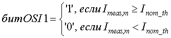

где Inom_th - номинальный порог помехи, Ihigh_th - верхний порог помехи, и Ihigh_th >Inom_th. Бит OSI 1 указывает, выше или ниже измеренная помеха номинального порога помехи. Бит OSI 2 указывает, выше или ниже измеренная помеха верхнего порога помехи. В этом варианте осуществления предполагается, что сектор m воспринимает низкую помеху, если измеренная помеха ниже Inom_th, высокую помеху, если измеренная помеха находится между Inom_th и Ihigh_th, и чрезмерную помеху, если измеренная помеха больше или равна Ihigh_th. Бит OSI 2 можно использовать для индикации чрезмерной помехи, воспринимаемой сектором.where I nom_th is the nominal interference threshold, I high_th is the upper interference threshold, and I high_th > I nom_th . The OSI 1 bit indicates whether the measured interference threshold is measured higher or lower. The OSI 2 bit indicates whether or not the measured interference of the upper interference threshold is higher or lower. In this embodiment, it is assumed that sector m perceives low interference if the measured interference is below I nom_th , high interference if the measured interference is between I nom_th and I high_th , and excessive interference if the measured interference is greater than or equal to I high_th . The OSI 2 bit can be used to indicate excessive interference perceived by the sector.
Согласно другому варианту осуществления, отчет OTA OSI включает в себя одно значение OSI, имеющее три уровня. Значение OSI можно задать следующим образом:According to another embodiment, the OTA OSI report includes one OSI value having three layers. The OSI value can be set as follows:

Трехуровневое значение OSI можно передавать с использованием векторной диаграммы сигнала, имеющей три точки сигнала. Например, значение OSI '0' можно передавать посредством символа 1+j0 или e j0, значение OSI '1' можно передавать посредством символа 0+j1 или e jπ/2, и значение OSI '2' можно передавать посредством символа -1+j0 или e jπ.A three-level OSI value can be transmitted using a signal vector diagram having three signal points. For example, an OSI value of '0' can be transmitted using a character 1+ j 0 or e j0 , an OSI value of '1' can be transmitted using a character 0 + j1 or e jπ / 2 , and an OSI value of '2' can be transmitted using a character -1+ j0 or e jπ .
Альтернативно, сектор m может получать измеренную помеху относительно теплового шума (IOT), т.е. отношение полной мощности помехи, воспринимаемой сектором m к мощности теплового шума. Полную мощность помехи можно вычислить, как описано выше. Мощность теплового шума можно оценивать, выключая передатчик и измеряя шум на приемнике. Для системы можно выбрать конкретную рабочую точку. Более высокая рабочая точка позволяет терминалам передавать, в среднем, на более высоких уровнях мощности. Однако высокая рабочая точка отрицательно влияет на энергетический баланс линии связи и может быть нежелательным. Для данной максимальной передаваемой мощности и данной скорости передачи данных допустимые максимальные потери на трассе уменьшаются с увеличением IOT. Очень высокая рабочая точка также нежелательна, поскольку система может приобрести ограничение на помеху, и в этом случае увеличение передаваемой мощности не приводит к увеличению SNR приема. Кроме того, очень высокая рабочая точка увеличивает вероятность дестабилизации системы. В любом случае, сектор m может задать свое трехуровневое значение OSI следующим образом:Alternatively, sector m may receive a measured interference with respect to thermal noise (IOT), i.e. the ratio of the total interference power perceived by sector m to the thermal noise power. The total interference power can be calculated as described above. The thermal noise power can be estimated by turning off the transmitter and measuring the noise at the receiver. You can select a specific operating point for the system. A higher operating point allows terminals to transmit, on average, at higher power levels. However, a high operating point negatively affects the energy balance of the communication line and may be undesirable. For a given maximum transmitted power and a given data rate, the allowable maximum path loss decreases with increasing IOT. A very high operating point is also undesirable, since the system may acquire an interference limitation, in which case an increase in transmitted power does not lead to an increase in reception SNR. In addition, a very high operating point increases the likelihood of system destabilization. In any case, sector m can set its three-level OSI value as follows:

где IOTnom_th - номинальный порог IOT и IOThigh_th верхний порог IOT.where IOT nom_th is the nominal threshold of IOT and IOT high_th is the upper threshold of IOT.
Биты/значения OSI также можно генерировать с использованием гистерезиса, чтобы индикация чрезмерной помехи не включалась слишком часто. Например, бит OSI 2 можно задавать равным '1' только, если измеренная помеха превышает верхний порог в течение первого промежутка времени TW1 (например, 50 миллисекунд), и можно задавать равным '0' только, если измеренная помеха ниже верхнего порога в течение второго промежутка времени TW2. В порядке другого примера, бит OSI 2 можно задавать равным '1' только, если измеренная помеха превышает первый верхний порог Ihigh_th1, и затем можно задавать равным '0' только, если измеренная помеха падает ниже второго верхнего порога Ihigh_th2, где Ihigh_th1>Ihigh_th2.OSI bits / values can also be generated using hysteresis so that the indication of excessive interference does not turn on too often. For example, bit OSI 2 can be set to '1' only if the measured interference exceeds the high threshold for a first period of time T W1 (e.g., 50 milliseconds) and can be set to '0' only if the measured interference is below the upper threshold for the second time interval T W2 . As another example, the OSI 2 bit can be set to '1' only if the measured noise exceeds the first upper threshold I high_th1 , and then it can be set to '0' only if the measured noise falls below the second upper threshold I high_th2 , where I high_th1 > I high_th2 .
Сектор m транслирует свой отчет OTA OSI, который может содержать два бита OSI или трехуровневое значение OSI, для пользовательского управления помехой. Сектор m может транслировать отчет OTA OSI различными способами. Согласно варианту осуществления, сектор m транслирует отчет OTA OSI в каждый период измерения. Согласно другому варианту осуществления, сектор m транслирует бит OSI 1 в каждый период измерения и транслирует бит OSI 2 только, если этот бит задан равным '1'. Сектор m также может транслировать OSI отчеты из других секторов на терминалы в секторе m для улучшения покрытия OSI.Sector m broadcasts its OTA OSI report, which may contain two OSI bits or a three-level OSI value, for user interference control. Sector m can broadcast OTA OSI reports in a variety of ways. According to an embodiment, sector m broadcasts an OTA OSI report in each measurement period. According to another embodiment, sector m translates the OSI 1 bit into each measurement period and only translates the OSI 2 bit if this bit is set to '1'. Sector m can also broadcast OSI reports from other sectors to terminals in sector m to improve OSI coverage.
Сектор m также передает свой отчет IS OSI в соседние секторы для сетевого управления помехой. Отчет IS OSI может содержать два бита OSI, трехуровневое значение OSI, измеренную помеху, квантованную до заранее определенного количества битов или неквантованную, IOTnom_th, IOThigh_th и IOTmeas,m; Inom_th, Ihigh_th и Imeas,m; потери на трассе, мощность, принимаемую с терминалов сектора m, измеряемую в других секторах, какую-либо другую информацию и их комбинации. Сектор m может передавать отчет IS OSI в каждый период измерения или если воспринимается чрезмерная помеха, или если выполняется какой-либо другой критерий. Другой сектор q также может запрашивать у сектора m отчет IS OSI, если терминалы в секторе q указывают, что они не могут принять биты OSI из сектора m. Каждый сектор использует отчеты IS OSI из соседних секторов для управления передачами данных с терминалов в своем секторе для ослабления межсекторной помехи в соседних секторах.Sector m also sends its IS OSI report to neighboring sectors for network interference management. An OSI IS report may contain two OSI bits, a three-level OSI value, a measured interference, quantized to a predetermined number of bits or non- quantized , IOT nom_th , IOT high_th and IOT meas, m ; I nom_th , I high_th and I meas, m ; path losses, power received from terminals of sector m , measured in other sectors, any other information and their combinations. Sector m may transmit an IS OSI report at each measurement period, either if excessive interference is perceived, or if some other criterion is met. Another sector q may also request an OSI IS report from sector m if the terminals in sector q indicate that they cannot receive OSI bits from sector m . Each sector uses IS OSI reports from neighboring sectors to control data transmissions from terminals in its sector to mitigate intersectoral interference in neighboring sectors.
Сетевое управление помехой можно обеспечивать различными способами. Некоторые варианты осуществления сетевого управления помехой описаны ниже.Network interference management can be provided in various ways. Some embodiments of network interference control are described below.
В одном варианте осуществления, сектор m осуществляет диспетчеризацию терминалов в секторе на основании отчетов IS OSI, полученных от соседних секторов. Например, если в одном или нескольких соседних секторах наблюдается чрезмерная помеха, то сектор m может снижать передаваемые мощности, используемые терминалами, лишенными преимуществ, в секторе m, чтобы эти терминалы создавали меньшую помеху для других секторов. Терминал, лишенный преимуществ, имеет малый коэффициент усиления канала (или большие потери на трассе) для обслуживающего сектора и вынужден передавать на высоком уровне мощности, чтобы достичь данного отношения сигнал/шум+помеха (SNR) в обслуживающем секторе. Терминал, лишенный преимуществ, обычно располагается ближе к соседнему сектору, и высокий уровень передаваемой мощности приводит к высокой межсекторной помехе для этого соседнего сектора.In one embodiment, sector m scheduling terminals in the sector based on IS OSI reports received from neighboring sectors. For example, if excessive interference is observed in one or more neighboring sectors, then sector m may reduce the transmitted powers used by terminals without advantages in sector m so that these terminals cause less interference to other sectors. The terminal, devoid of advantages, has a small channel gain (or large path loss) for the serving sector and is forced to transmit at a high power level to achieve this signal-to-noise + interference (SNR) ratio in the serving sector. A disadvantaged terminal is usually located closer to the neighboring sector, and a high level of transmitted power leads to high intersector interference for this neighboring sector.
Сектор m может идентифицировать терминалы, лишенные преимуществ, на основании различных метрик качества, например коэффициента усиления канала, интенсивности пилот-сигнала, отношения сигнал/шум (C/N), отношения коэффициентов усиления канала и т.п. Эти метрики качества можно оценивать на основании пилот-сигнала и/или других сигналов, передаваемых терминалами. Например, оценочный коэффициент усиления канала для терминала можно сравнивать с пороговым коэффициентом усиления канала, и терминал можно считать терминалом, лишенным преимуществ, если его коэффициент усиления канала ниже порогового коэффициента усиления канала. Дополнительно, терминалы, лишенные преимуществ, можно идентифицировать в отчете IS OSI совместно с их измеренными значениями, например IOTmeas,m или измеренной принимаемой мощностью. Дополнительно, в ряде случаев, отчет IS OSI может обеспечивать, помимо прочего, информацию для идентификации терминалов для использования разных подходов, описанных ниже.Sector m can identify terminals without advantages based on various quality metrics, for example, channel gain, pilot intensity, signal to noise ratio (C / N), channel gain ratios, and the like. These quality metrics can be estimated based on the pilot and / or other signals transmitted by the terminals. For example, the estimated channel gain for the terminal can be compared with a threshold channel gain, and the terminal can be considered a terminal without advantages if its channel gain is lower than the channel threshold gain. Additionally, terminals deprived of advantages can be identified in the IS OSI report together with their measured values, for example, IOT meas, m or measured received power. Additionally, in some cases, the IS OSI report may provide, among other things, information for identifying terminals for using the different approaches described below.
Сектор m может снижать передаваемые мощности, используемые терминалами, лишенными преимуществ, 1) уменьшая верхний предел передаваемой мощности, который применим к терминалам, 2) уменьшая нижний предел передаваемой мощности, который применим к терминалам, 3) назначая терминалам, лишенным преимуществ, более низкие скорости передачи данных, которые требуют более низких SNR и, следовательно, более низких передаваемых мощностей, 4) не планируя передачи данных для терминалов, лишенных преимуществ, или 5) используя какой-либо другой метод или комбинацию методов.Sector m can reduce the transmitted power used by terminals without advantages, 1) reducing the upper limit of transmitted power, which is applicable to terminals, 2) reducing the lower limit of transmitted power, which is applicable to terminals, 3) assigning lower speeds to terminals without advantages data transmissions that require lower SNRs and therefore lower transmitted powers, 4) not planning data transmissions for terminals without advantages, or 5) using any other method or combi ation methods.
Согласно другому варианту осуществления, сектор m использует управление доступом для ослабления межсекторной помехи, воспринимаемой соседними секторами. Например, если в одном или нескольких соседних секторах наблюдается чрезмерная помеха, то сектор m может снижать количество активных терминалов в секторе, 1) блокируя доступ к новым терминалам, запрашивающим передачу по обратной линии связи, 2) блокируя доступ к терминалам, лишенным преимуществ, 3) отменяя назначение терминалов, которым уже был предоставлен доступ, 4) отменяя назначение терминалов, лишенных преимуществ, или 5) используя какие-либо другие методы управления доступом. Частоту отмены назначения терминалов также можно сделать функцией отчетов IS OSI от соседних секторов (например, воспринимаемых уровней помехи), количества соседних секторов, воспринимающих чрезмерную помеху, и/или других факторов. Таким образом, сектор m может регулировать нагрузку сектора на основании отчетов IS OSI от соседних секторов.According to another embodiment, sector m uses access control to mitigate intersector interference perceived by neighboring sectors. For example, if excessive interference is observed in one or several neighboring sectors, then sector m can reduce the number of active terminals in the sector, 1) blocking access to new terminals requesting transmission on the reverse link, 2) blocking access to terminals without advantages, 3 ) canceling the assignment of terminals that have already been granted access, 4) canceling the assignment of terminals without advantages, or 5) using any other access control methods. The frequency of terminal unassignment can also be made a function of IS OSI reports from neighboring sectors (for example, perceived interference levels), the number of neighboring sectors perceiving excessive interference, and / or other factors. Thus, sector m can adjust the sector load based on IS OSI reports from neighboring sectors.
Согласно еще одному варианту осуществления, сектор m назначает каналы трафика терминалам в секторе таким образом, чтобы ослаблять межсекторную помеху, воспринимаемую соседними секторами. Например, каждому сектору может быть назначен набор каналов трафика, которые могут по очереди назначаться терминалам в секторе. Соседние секторы также могут совместно использовать общий набор каналов трафика, ортогональный набору каналов трафика, назначенных каждому сектору. Если в одном или нескольких соседних секторах наблюдается чрезмерная помеха, то сектор m может назначить терминалам, лишенным преимуществ, в секторе m каналы трафика в общем наборе. В таком случае, эти терминалы, лишенные преимуществ, не будут создавать помеху для соседних секторов, поскольку каналы трафика в общем наборе ортогональны каналам трафика, назначенным соседним секторам. В порядке другого примера, каждому сектору может быть назначен набор каналов трафика, которые могут назначаться мощным терминалам, для которых допустимы высокие уровни помехи. Если в одном или нескольких соседних секторах наблюдается чрезмерная помеха, то сектор m может назначать терминалам, лишенным преимуществ, в секторе m каналы трафика, назначенные мощным терминалам в соседних секторах.According to yet another embodiment, sector m assigns traffic channels to terminals in the sector so as to attenuate inter-sector interference perceived by neighboring sectors. For example, each sector can be assigned a set of traffic channels that can be assigned in turn to terminals in the sector. Neighboring sectors can also share a common set of traffic channels orthogonal to the set of traffic channels assigned to each sector. If excessive interference is observed in one or several neighboring sectors, then sector m may assign traffic channels in the common set to terminals without advantages in sector m . In this case, these terminals, deprived of advantages, will not interfere with neighboring sectors, since the traffic channels in the common set are orthogonal to the traffic channels assigned to neighboring sectors. As another example, each sector can be assigned a set of traffic channels that can be assigned to powerful terminals for which high levels of interference are acceptable. If excessive interference is observed in one or several neighboring sectors, then sector m can assign traffic channels assigned to powerful terminals in neighboring sectors in sector m to sectors m .
Комбинацию одного или нескольких из вышеописанных подходов также можно использовать для обеспечения гибкости или для других целей.A combination of one or more of the above approaches can also be used to provide flexibility or for other purposes.
Для простоты, вышеприведенное описание относится, в основном, к одному сектору m. Каждый сектор в системе может осуществлять вышеописанное управление помехой для сектора m.For simplicity, the above description relates mainly to one sector m . Each sector in the system can perform the above interference control for sector m .
Пользовательское управление помехой также можно обеспечивать различными способами. Согласно варианту осуществления, пользовательское управление помехой осуществляется, когда терминалам разрешено автономно регулировать свои передаваемые мощности на основании отчетов OTA OSI, полученных от соседних секторов.User interference control can also be provided in various ways. According to an embodiment, user interference control is performed when the terminals are allowed to autonomously adjust their transmit powers based on OTA OSI reports received from neighboring sectors.
Заметим, что, хотя на фиг.2 описано использование как сетевого, так и пользовательского управления помехой, можно использовать только один подход. Например, блоки 212 и 214 можно упразднить, и все управление помехой можно обеспечить с использованием только сетевого управления помехой, например, рассмотренного в отношении блоков 222-228.Note that, although FIG. 2 describes the use of both network and user interference control, only one approach can be used. For example, blocks 212 and 214 can be eliminated, and all interference control can be achieved using only network interference control, for example, discussed in relation to blocks 222-228.
На фиг.3 показан процесс 300, осуществляемый одним терминалом u для управления помехой. Терминал u принимает отчет OTA OSI от соседнего сектора (блок 312). Затем производится определение, воспринимает ли соседний сектор чрезмерную помеху, например, равен ли бит OSI 2 '1' (блок 314). Если ответ 'Да', терминал u снижает свою передаваемую мощность с увеличенным шагом уменьшения и/или в более высоком темпе (блок 316). В противном случае, производится определение, воспринимает ли соседний сектор высокую помеху, например, равны ли бит OSI 1 '1' и бит OSI 2 '0' соответственно (блок 318). Если ответ 'Да', терминал u снижает свою передаваемую мощность с номинальным шагом уменьшения и/или в номинальном темпе (блок 320). В противном случае, терминал u увеличивает свою передаваемую мощность с номинальным шагом увеличения и/или в номинальном темпе (блок 322).FIG. 3 shows a
На фиг.3 показан вариант осуществления, согласно которому отчет OTA OSI отражает межсекторную помеху, воспринимаемую соседним сектором, посредством одного из трех возможных уровней - низкого, высокого и чрезмерного. Процесс 300 можно распространить на любое количество уровней помехи. В общем случае, передаваемую мощность для терминала u можно (1) снижать с шагом уменьшения, имеющим прямую зависимость от величины помехи, воспринимаемой соседним сектором (например, чем больше помеха, тем больше шаг уменьшения), когда измеренная помеха выше данного порога, и/или (2) увеличивать с шагом увеличения, который имеет обратную зависимость от величины помехи, воспринимаемой соседним сектором (например, чем меньше помеха, тем больше шаг увеличения), когда измеренная помеха ниже данного порога. Величину шага и/или темп регулировки также можно определять на основании других параметров, например, текущего уровня передаваемой мощности для терминала, коэффициента усиления канала для соседнего сектора относительно коэффициента усиления канала для обслуживающего сектора, предыдущих отчетов OTA OSI и т.д.Figure 3 shows an embodiment according to which the OTA OSI report reflects intersectoral interference perceived by the neighboring sector through one of three possible levels - low, high and excessive.
Терминал u может регулировать свою передаваемую мощность на основании отчета OTA OSI от одного или множества соседних секторов. Терминал u может оценивать коэффициент усиления канала для каждого сектора на основании пилот-сигнала, принятого от сектора. Затем терминал u может выводить отношение коэффициентов усиления канала для каждого соседнего сектора следующим образом:Terminal u may adjust its transmit power based on an OTA OSI report from one or a plurality of neighboring sectors. Terminal u may estimate the channel gain for each sector based on a pilot received from the sector. Then, terminal u can output the ratio of the channel gains for each neighboring sector as follows:
![]()
![]()
где g ns,i(n) - коэффициент усиления канала между терминалом u и соседним сектором i;where g ns, i ( n ) is the gain of the channel between terminal u and neighboring sector i ;
g ss(n) - коэффициент усиления канала между терминалом u и обслуживающим сектором; и g ss ( n ) is the channel gain between terminal u and the serving sector; and
r i(n) - отношение коэффициентов усиления канала для соседнего сектора i. r i ( n ) is the ratio of the channel gains for the neighboring sector i .
В одном варианте осуществления, терминал u идентифицирует самый мощный соседний сектор с наибольшим отношением коэффициентов усиления канала. Затем терминал u регулирует свою передаваемую мощность на основании отчета OTA OSI только от этого самого мощного соседнего сектора. Согласно другому варианту осуществления, терминал u регулирует свою передаваемую мощность на основании отчетов OTA OSI от всех секторов в наборе OSI. Этот набор OSI может содержать (1) T самых мощных соседних секторов, где T≥1, (2) соседние секторы с отношением коэффициентов усиления канала, превышающим пороговое отношение коэффициентов усиления канала, (3) соседние секторы с коэффициентами усиления канала, превышающими пороговый коэффициент усиления канала, (4) соседние секторы, включенные в список соседей, рассылаемый обслуживающим сектором, или (5) какую-либо другую группу соседних секторов. Терминал u может регулировать свою передаваемую мощность различными способами на основании отчетов OTA OSI от множества соседних секторов из набора OSI. Например, терминал u может снижать свою передаваемую мощность, если какой-либо соседний сектор из набора OSI воспринимает высокую или чрезмерную помеху. В порядке другого примера, терминал u может определять регулировку передаваемой мощности для каждого соседнего сектора из набора OSI и затем может объединять регулировки для всех соседних секторов из набора OSI для получения общей регулировки передаваемой мощности.In one embodiment, terminal u identifies the most powerful neighboring sector with the highest channel gain ratio. Then, the terminal u adjusts its transmitted power based on the OTA OSI report only from this most powerful neighboring sector. According to another embodiment, terminal u adjusts its transmit power based on OTA OSI reports from all sectors in the OSI set. This OSI set may contain (1) T the most powerful neighboring sectors, where T≥1, (2) neighboring sectors with a channel gain ratio exceeding the threshold ratio of channel gain, (3) neighboring sectors with channel gain factors exceeding the threshold coefficient channel amplification, (4) neighboring sectors included in the neighbor list sent by the serving sector, or (5) any other group of neighboring sectors. Terminal u may adjust its transmit power in various ways based on the OTA OSI reports from multiple neighbor sectors from a set of OSI. For example, terminal u can reduce its transmit power if any neighboring sector from the OSI set receives high or excessive interference. As another example, terminal u may determine the adjustment of the transmitted power for each neighboring sector from the OSI set and then may combine the adjustments for all neighboring sectors from the OSI set to obtain an overall adjustment of the transmitted power.
В общем случае, регулировку передаваемой мощности для управления помехой можно осуществлять в связи с различными схемами управления мощностью. Для простоты, конкретная схема управления мощностью описана ниже. Для этой схемы управления мощностью передаваемую мощность для канала трафика, назначенного терминалу u, можно выразить в виде:In general, the adjustment of the transmitted power to control the interference can be carried out in connection with various power control schemes. For simplicity, a specific power control scheme is described below. For this power control scheme, the transmitted power for the traffic channel assigned to terminal u can be expressed as:
![]()
![]()
где Pdch(n) - передаваемая мощность для канала трафика для интервала обновления n;where P dch ( n ) is the transmitted power for the traffic channel for the update interval n ;
Pref(n) - опорный уровень мощности для интервала обновления n; иP ref ( n ) is the reference power level for the update interval n ; and
ΔP(n) - дельта передаваемой мощности для интервала обновления n.ΔP ( n ) is the transmit power delta for the update interval n .
Уровни передаваемой мощности Pdch(n) и Pref(n) и дельта передаваемой мощности ΔP(n) заданы в децибелах (дБ).The transmit power levels P dch ( n ) and P ref ( n ) and the transmit power delta ΔP ( n ) are specified in decibels (dB).
Опорный уровень мощности Pref(n) - это величина передаваемой мощности, необходимая для получения целевого SNR для указанной передачи, которая может представлять собой сигнализацию, передаваемую терминалом u по каналу управления, или какую-либо другую передачу. Опорный уровень мощности и целевое SNR можно регулировать для достижения нужного уровня производительности для указанной передачи, например, 1% уровня пакетной ошибки (PER). Если передача данных по каналу трафика и указанная передача находятся в сходных условиях шума и помехи, то SNR приема для передачи данных, SNRdch(n), можно оценивать следующим образом:The reference power level P ref ( n ) is the amount of transmitted power needed to obtain the target SNR for the specified transmission, which may be the signaling transmitted by the terminal u through the control channel, or some other transmission. The reference power level and the target SNR can be adjusted to achieve the desired performance level for the specified transmission, for example, 1% packet error level (PER). If the data transmission on the traffic channel and the specified transmission are in similar noise and interference conditions, then the receiving SNR for data transmission, SNR dch ( n ), can be estimated as follows:
![]()
![]()
Дельту передаваемой мощности ΔP(n) можно регулировать детерминированным способом, вероятностным способом или каким-либо другим способом на основании отчетов OTA OSI от соседних секторов. Передаваемую мощность можно регулировать (1) в разной степени для разных уровней помехи с использованием детерминированной регулировки или (2) в разных темпах для разных уровней помехи с использованием вероятностной регулировки. Иллюстративные детерминированная и вероятностная схемы регулировки передаваемой мощности описаны ниже. Для простоты, нижеследующее описание относится к регулировке передаваемой мощности для бита OSI, принимаемого от одного соседнего сектора. Этот бит OSI может быть битом OSI 1 или 2.The transmit power delta ΔP ( n ) can be adjusted in a deterministic, probabilistic, or some other way based on OTA OSI reports from neighboring sectors. The transmitted power can be adjusted (1) to different degrees for different levels of interference using deterministic adjustment or (2) at different rates for different levels of interference using probabilistic adjustment. Illustrative deterministic and probabilistic transmit power control schemes are described below. For simplicity, the following description relates to adjusting the transmit power for an OSI bit received from one neighboring sector. This OSI bit may be OSI bit 1 or 2.
На фиг.4 показан процесс 400 регулировки передаваемой мощности терминала u детерминированным способом. Первоначально терминал u обрабатывает отчет OTA OSI от соседнего сектора (блок 412) и определяет, равен ли бит OSI '1' или '0' (блок 414). Если бит OSI равен '1', что указывает, что воспринимаемая помеха превышает порог помехи, терминал u определяет величину снижения передаваемой мощности или шаг уменьшения ΔPdn(n) (блок 422). ΔPdn(n) можно определить на основании дельты передаваемой мощности для предыдущего интервала обновления, ΔP(n-1), и отношения коэффициентов усиления канала для соседнего сектора, r
ns(n). Затем терминал u уменьшает дельту передаваемой мощности на ΔPdn(n) (блок 424). Если же бит OSI равен '0', терминал u определяет величину повышения передаваемой мощности или шаг увеличения ΔPup(n) (блок 432). ΔPup(n) также можно определять на основании ΔP(n-1) и r
ns(n). Затем терминал u увеличивает дельту передаваемой мощности на ΔPup(n) (блок 434). Регулировки передаваемой мощности в блоках 424 и 434 можно выразить следующим образом:4, a

После блоков 424 и 434, терминал u ограничивает дельту передаваемой мощности ΔP(n) в пределах допустимых значений дельты передаваемой мощности (блок 442) следующим образом:After
![]()
![]()
где ΔPmin - минимальная дельта передаваемой мощности, допустимая для канала трафика, иwhere ΔP min is the minimum transmit power delta allowed for the traffic channel, and
ΔPmax - максимальная дельта передаваемой мощности, допустимая для канала трафика.ΔP max - maximum transmit power delta allowed for the traffic channel.
Ограничивая значения дельты передаваемой мощности для всех терминалов в секторе в диапазоне дельты передаваемой мощности, согласно уравнению (13), можно поддерживать внутрисекторную помеху на приемлемых уровнях. Минимальную дельту передаваемой мощности ΔPmin можно регулировать посредством контура управления, чтобы гарантировать, что каждый терминал может отвечать требованиям класса качества обслуживания (QoS), которому принадлежит терминал. ΔPmin для разных классов QoS можно регулировать в разных темпах и/или с разным шагом.By limiting the transmit power delta values for all terminals in the sector in the transmit power delta range, according to equation (13), intra-sector interference can be maintained at acceptable levels. The minimum transmit power delta ΔP min can be adjusted via a control loop to ensure that each terminal can meet the requirements of the quality of service (QoS) class to which the terminal belongs. ΔP min for different QoS classes can be adjusted at different rates and / or with different steps.
Затем терминал u вычисляет передаваемую мощность Pdch(n) канала трафика на основании дельты передаваемой мощности ΔP(n) и опорного уровня мощности Pref(n), согласно уравнению (10) (блок 444). Терминал u может ограничивать передаваемую мощность Pdch(n) максимальным уровнем мощности Pmax (блок 446) следующим образом:Then, the terminal u calculates the transmitted power P dch ( n ) of the traffic channel based on the transmit power delta ΔP ( n ) and the reference power level P ref ( n ) according to equation (10) (block 444). The terminal u may limit the transmitted power P dch ( n ) to the maximum power level P max (block 446) as follows:

Терминал u использует передаваемую мощность Pdch(n) для передачи данных по каналу трафика.The terminal u uses the transmitted power P dch ( n ) to transmit data on the traffic channel.
Согласно варианту осуществления, величины шага ΔPdn(n) и ΔPup(n) можно вычислить следующим образом:According to an embodiment, the step values ΔP dn ( n ) and ΔP up ( n ) can be calculated as follows:
![]()
![]()
![]()
![]()
где ΔPdn,min и ΔPup,min - минимальные значения для ΔPdn(n) и ΔPup(n) соответственно;where ΔP dn, min and ΔP up, min are the minimum values for ΔP dn ( n ) and ΔP up ( n ), respectively;
kdn и kup - масштабные коэффициенты для ΔPdn(n) и ΔPup(n) соответственно; иk dn and k up are scale factors for ΔP dn ( n ) and ΔP up ( n ), respectively; and
f dn() и f up() - функции для вычисления ΔPdn(n) и ΔPup(n) соответственно. f dn () and f up () are functions for calculating ΔP dn ( n ) and ΔP up ( n ), respectively.
Функцию f dn() можно задать так, чтобы ΔPdn(n) находился в прямой зависимости от ΔP(n-1) и r ns(n). Если соседний сектор воспринимает высокую или чрезмерную помеху, то (1) увеличение коэффициента усиления канала для соседнего сектора приводит к увеличению ΔPdn(n), и (2) увеличение значения ΔP(n-1) приводит к увеличению ΔPdn(n). Функцию f up() можно задать так, чтобы ΔPup(n) находился в обратной зависимости от ΔP(n-1) и r ns(n). Если соседний сектор воспринимает низкую помеху, то (1) увеличение коэффициента усиления канала для соседнего сектора приводит к уменьшению ΔPup(n) и (2) увеличение значения ΔP(n-1) приводит к уменьшению ΔPup(n).The function f dn () can be defined so that ΔP dn (n) is directly dependent on ΔP (n-1) and r ns ( n ). If the neighboring sector receives high or excessive interference, then (1) an increase in the channel gain for the neighboring sector leads to an increase in ΔP dn ( n ), and (2) an increase in ΔP ( n -1) leads to an increase in ΔP dn ( n ). The function f up () can be defined so that ΔP up ( n ) is inversely related to ΔP ( n -1) and r ns ( n ). If the neighboring sector perceives low interference, then (1) an increase in the channel gain for the neighboring sector leads to a decrease in ΔP up ( n ) and (2) an increase in ΔP ( n -1) leads to a decrease in ΔP up ( n ).
На фиг.4 показана обработка для одного бита OSI от одного соседнего сектора. Когда соседний сектор воспринимает чрезмерную помеху, можно использовать большее значение ΔPdn(n). Когда соседний сектор воспринимает высокую помеху, можно использовать меньшее значение ΔPdn(n). Разные величины шага уменьшения можно получать, например, используя разные масштабные коэффициенты kdn1 и kdn2 для высокой и чрезмерной помехи соответственно.Figure 4 shows the processing for one OSI bit from one neighboring sector. When the neighboring sector perceives excessive interference, a larger value ΔP dn ( n ) can be used. When a neighboring sector receives high interference, a lower ΔP dn ( n ) value can be used. Different values of the reduction step can be obtained, for example, using different scale factors k dn1 and k dn2 for high and excessive interference, respectively.
На фиг.5 показан процесс 500 регулировки передаваемой мощности терминала u вероятностным способом. Первоначально терминал u обрабатывает отчет OTA OSI от соседнего сектора (блок 512) и определяет, равен ли бит OSI '1' или '0' (блок 514). Если бит OSI равен '1', то терминал u определяет вероятность снижения передаваемой мощности, Prdn(n), например, на основании ΔP(n-1) и r ns(n) (блок 522). Затем терминал u произвольно выбирает значение x между 0,0 и 1,0, где x - это случайная переменная, равномерно распределенная между 0,0 и 1,0 (блок 524). Если в блоке 526 определено, что x меньше или равна Prdn(n), то терминал u уменьшает свою дельту передаваемой мощности на ΔPdn (блок 528). Если же x больше Prdn(n), то терминал u поддерживает дельту передаваемой мощности на текущем уровне (блок 530).5, a process 500 for adjusting the transmitted power of the terminal u in a probabilistic manner is shown. Initially, terminal u processes an OTA OSI report from a neighboring sector (block 512) and determines whether the OSI bit is '1' or '0' (block 514). If the OSI bit is '1', then the terminal u determines the probability of a decrease in the transmitted power, Pr dn ( n ), for example, based on ΔP ( n -1) and r ns ( n ) (block 522). Then, terminal u arbitrarily selects a value of x between 0.0 and 1.0, where x is a random variable uniformly distributed between 0.0 and 1.0 (block 524). If at block 526 it is determined that x is less than or equal to Pr dn ( n ), then terminal u decreases its transmit power delta by ΔP dn (block 528). If x is greater than Pr dn ( n ), then terminal u maintains the transmit power delta at the current level (block 530).
Если в блоке 514 определено, что бит OSI равен '0', то терминал u определяет вероятность увеличения передаваемой мощности, Prup(n), например, на основании ΔP(n-1) и r ns(n) (блок 532). Затем терминал u произвольно выбирает значение x между 0,0 и 1,0 (блок 534). Если в блоке 536 определено, что x меньше или равна Prup(n), то терминал u увеличивает свою дельту передаваемой мощности на ΔPup (блок 538). Если же x больше, чем Prup(n), то терминал u поддерживает дельту передаваемой мощности на текущем уровне (блок 530). Регулировки передаваемой мощности в блоках 528, 530, и 538 можно выразить следующим образом:If it is determined in block 514 that the OSI bit is '0', then terminal u determines the probability of increased transmitted power, Pr up ( n ), for example, based on ΔP ( n -1) and r ns ( n ) (block 532). Then, terminal u arbitrarily selects an x value between 0.0 and 1.0 (block 534). If it is determined in block 536 that x is less than or equal to Pr up ( n ), then terminal u increases its transmit power delta by ΔP up (block 538). If x is greater than Pr up ( n ), then terminal u maintains the transmit power delta at the current level (block 530). The adjustment of the transmitted power in blocks 528, 530, and 538 can be expressed as follows:

ΔPdn и ΔPup могут иметь одинаковые значения (например, 0,25 дБ, 0,5 дБ, 1,0 дБ и т.д.) или разные значения.ΔP dn and ΔP up can have the same values (for example, 0.25 dB, 0.5 dB, 1.0 dB, etc.) or different values.
После блоков 528, 530 и 538 терминал u ограничивает дельту передаваемой мощности, согласно уравнению (13) (блок 542). Затем терминал u вычисляет передаваемую мощность Pdch(n) на основании дельты передаваемой мощности ΔP(n) и опорного уровня мощности Pref(n), согласно уравнению (10) (блок 544), и дополнительно ограничивает передаваемую мощность Pdch(n) максимальным уровнем мощности, согласно уравнению (14) (блок 546). Терминал u использует передаваемую мощность Pdch(n) для передачи данных по каналу трафика. Согласно варианту осуществления, вероятности вычисляются следующим образом:After blocks 528, 530 and 538, terminal u limits the transmit power delta according to equation (13) (block 542). Then, the terminal u calculates the transmit power P dch ( n ) based on the transmit power delta ΔP ( n ) and the reference power level P ref ( n ) according to equation (10) (block 544), and further limits the transmit power P dch ( n ) maximum power level, according to equation (14) (block 546). The terminal u uses the transmitted power P dch ( n ) to transmit data on the traffic channel. According to an embodiment, the probabilities are calculated as follows:
![]()
![]()
![]()
![]()
где Prdn,min и Prup,min - минимальные значения Prdn(n) и Prup(n), соответственно; иwhere Pr dn, min and Pr up, min are the minimum values of Pr dn ( n ) and Pr up ( n ), respectively; and
f′dn() и f′up() - функции для вычисления Prdn(n) и Prup(n) соответственно.f ′ dn () and f ′ up () are functions for calculating Pr dn ( n ) and Pr up ( n ), respectively.
Функцию f′dn() можно задать так, чтобы Prdn(n) находилась в прямой зависимости от ΔP(n-1) и r ns(n). Если соседний сектор воспринимает высокую или чрезмерную помеху, то (1) увеличение коэффициента усиления канала для соседнего сектора приводит к увеличению Prdn(n) и (2) увеличение значения ΔP(n-1) приводит к увеличению Prdn(n). Увеличение Prdn(n) приводит к увеличению вероятности снижения передаваемой мощности. Функцию f′up() можно задать так, чтобы Prup(n) находилась в обратной зависимости от ΔP(n-1) и r ns(n). Если соседний сектор воспринимает низкую помеху, то (1) увеличение коэффициента усиления канала для соседнего сектора приводит к уменьшению Prup(n) и (2) увеличение значения ΔP(n-1) приводит к уменьшению Prup(n). Уменьшение Prup(n) приводит к уменьшению вероятности повышения передаваемой мощности.The function f ′ dn () can be defined so that Pr dn ( n ) is directly dependent on ΔP ( n -1) and r ns ( n ). If the neighboring sector receives high or excessive interference, then (1) an increase in the channel gain for the neighboring sector leads to an increase in Pr dn ( n ) and (2) an increase in ΔP ( n -1) leads to an increase in Pr dn ( n ). An increase in Pr dn ( n ) leads to an increase in the probability of a decrease in transmitted power. The function f ′ up () can be defined so that Pr up ( n ) is inversely related to ΔP ( n -1) and r ns ( n ). If the neighboring sector perceives low interference, then (1) an increase in the channel gain for the neighboring sector leads to a decrease in Pr up ( n ) and (2) an increase in ΔP ( n -1) leads to a decrease in Pr up ( n ). A decrease in Pr up ( n ) leads to a decrease in the probability of an increase in the transmitted power.
На фиг.5 показана обработка для одного бита OSI от одного соседнего сектора. Когда соседний сектор воспринимает чрезмерную помеху, можно использовать большее значение Prdn(n). Когда соседний сектор воспринимает высокую помеху, можно использовать меньшее значение Prdn(n). Разные вероятности снижения и, следовательно, разные темпы регулировки мощности можно получать, например, используя разные масштабные коэффициенты kdn1 и kdn2 для высокой и чрезмерной помехи соответственно.5 shows processing for one OSI bit from one neighboring sector. When the neighboring sector perceives excessive interference, a larger value of Pr dn ( n ) can be used. When a neighboring sector receives high interference, a lower Pr dn ( n ) value can be used. Different reduction probabilities and, therefore, different rates of power adjustment can be obtained, for example, using different scale factors k dn1 and k dn2 for high and excessive interference, respectively.
В общем случае, различные функции можно использовать для вычисления величин шага ΔPdn(n) и ΔPup(n) и вероятностей Prdn(n) и Prup(n). Функцию можно задавать на основании различных параметров, например текущей передаваемой мощности, текущей дельты передаваемой мощности, текущего отчета OTA OSI, предыдущих отчетов OTA OSI, коэффициентов усиления канала и т.д. Разные функции могут по-разному влиять на различные характеристики управления мощностью, например, скорость схождения регулировки передаваемой мощности и распределение значений дельты передаваемой мощности для терминалов в системе. Величины шага и вероятности также можно определять на основании поисковых таблиц или иными средствами.In the general case, various functions can be used to calculate the step sizes ΔP dn ( n ) and ΔP up ( n ) and the probabilities Pr dn ( n ) and Pr up ( n ). The function can be set based on various parameters, for example, the current transmitted power, the current delta of the transmitted power, the current OTA OSI report, previous OTA OSI reports, channel gain, etc. Different functions may have different effects on various power control characteristics, for example, the convergence rate of the transmitted power adjustment and the distribution of the transmitted power deltas for the terminals in the system. The values of step and probability can also be determined on the basis of search tables or other means.
Вышеописанные регулировку передаваемой мощности и/или управление вводом также можно осуществлять на основании класса QoS, класса приоритета пользователя и пр. Например, терминал, использующий экстренную связь, и полицейский терминал могут иметь более высокий приоритет и могут иметь возможность регулировать передаваемую мощность в более высоком темпе и/или с шагом большего размера, чем пользователь с нормальным приоритетом. В порядке другого примера, терминал, передающий речевой трафик, может регулировать передаваемую мощность в более медленном темпе и/или с шагом меньшего размера.The above-described adjustment of the transmitted power and / or input control can also be performed based on the QoS class, user priority class, etc. For example, an emergency communication terminal and a police terminal may have a higher priority and may be able to adjust the transmitted power at a higher rate. and / or in larger increments than the normal priority user. In another example, a terminal transmitting voice traffic can adjust the transmitted power at a slower pace and / or in smaller steps.
Терминал u также может изменять режим регулировки передаваемой мощности на основании предыдущих отчетов OTA OSI, полученных из соседних секторов. Например, терминал u может снижать свою передаваемую мощность с конкретным шагом уменьшения и/или в конкретном темпе, если соседний сектор сообщает о чрезмерной помехе, и может снижать передаваемую мощность с шагом уменьшения большего размера и/или в более высоком темпе, если соседний сектор продолжает сообщать о чрезмерной помехе. Альтернативно или дополнительно, терминал u может игнорировать ΔPmin в уравнении (13), если соседний сектор сообщает о чрезмерной помехе, или если соседний сектор продолжает сообщать о чрезмерной помехе.Terminal u can also change the mode of adjustment of transmitted power based on previous OTA OSI reports received from neighboring sectors. For example, terminal u can reduce its transmit power with a specific decrease step and / or at a particular pace if the neighboring sector reports excessive interference, and can reduce the transmit power with a decrease step in a larger and / or higher pace if the neighboring sector continues Report excessive interference. Alternatively or additionally, terminal u may ignore ΔP min in equation (13) if the neighboring sector reports excessive interference, or if the neighboring sector continues to report excessive interference.
Различные варианты осуществления управления мощностью для ослабления межсекторной помехи были описаны выше. Управление помехой и мощностью также можно осуществлять другими способами, не выходя за рамки объема изобретения.Various power control embodiments for mitigating intersector interference have been described above. Interference and power control can also be done in other ways, without going beyond the scope of the invention.
Согласно варианту осуществления, каждый сектор транслирует свой отчет OTA OSI на терминалы в соседних секторах, как описано выше. Отчет OTA OSI может транслироваться с достаточной передаваемой мощностью для достижения нужного покрытия в соседних секторах. Каждый терминал может принимать отчеты OTA OSI от соседних секторов и обрабатывать эти отчеты OTA OSI таким образом, чтобы добиваться достаточно низкой частоты ложного необнаружения и достаточно низкой вероятности ложной тревоги. Ложное необнаружение означает неудачу в обнаружении переданного бита или значения OSI. Ложная тревога означает ошибочное обнаружение принятого бита OSI или значения. Например, если бит OSI передается с использованием BPSK, терминал может декларировать принятый бит OSI, равным (1) '0', если обнаруженный бит OSI ниже первого порога, бит OSI<-Bth, (2) '1', если обнаруженный бит OSI превышает второй порог, бит OSI>+Bth, и (3) пустой бит в противном случае, +Bth≥бит OSI≥-Bth. Терминал обычно может достигать компромисса между частотой ложного необнаружения с вероятностью ложной тревоги, регулируя пороги, используемые для обнаружения.According to an embodiment, each sector broadcasts its OTA OSI report to terminals in neighboring sectors, as described above. The OTA OSI report can be broadcast with sufficient transmitted power to achieve the desired coverage in neighboring sectors. Each terminal can receive OTA OSI reports from neighboring sectors and process these OTA OSI reports in such a way as to achieve a sufficiently low false detection rate and a sufficiently low probability of false alarm. False non-detection means failure to detect a transmitted bit or OSI value. False alarm means erroneous detection of a received OSI bit or value. For example, if an OSI bit is transmitted using BPSK, the terminal may declare the received OSI bit equal to (1) '0' if the detected OSI bit is below the first threshold, OSI bit <-B th , (2) '1' if the detected bit OSI exceeds the second threshold, the OSI bit> + B th , and (3) an empty bit otherwise, + B th ≥ bit OSI≥-B th . A terminal can usually compromise between the frequency of false detection and the probability of false alarm by adjusting the thresholds used for detection.
Согласно другому варианту осуществления, каждый сектор также транслирует отчеты OTA OSI, генерируемые соседними секторами, на терминалы в этом секторе. Таким образом, каждый сектор играет роль посредника для соседних секторов. Этот вариант осуществления может гарантировать, что каждый терминал может надежно принимать отчеты OTA OSI, генерируемые соседними секторами, поскольку терминал может принимать эти отчеты OTA OSI от обслуживающего сектора. Этот вариант осуществления хорошо подходит для построения асимметричной сети, в которой зоны покрытия сектора имеют разные размеры. Секторы меньшего размера обычно передают на более низких уровнях мощности, и отчеты OTA OSI, транслируемые этими секторами меньшего размера, не могут надежно приниматься терминалами в соседних секторах. Тогда секторы меньшего размера будут пользоваться отчетами OTA OSI, транслируемыми соседними секторами.According to another embodiment, each sector also broadcasts OTA OSI reports generated by neighboring sectors to terminals in that sector. Thus, each sector acts as an intermediary for neighboring sectors. This embodiment can ensure that each terminal can reliably receive OTA OSI reports generated by neighboring sectors, since the terminal can receive these OTA OSI reports from the serving sector. This embodiment is well suited for constructing an asymmetric network in which sector coverage areas are of different sizes. Smaller sectors are typically transmitted at lower power levels, and OTA OSI reports broadcast by these smaller sectors cannot be reliably received by terminals in neighboring sectors. Smaller sectors will then use OTA OSI reports broadcast by neighboring sectors.
В общем случае, данный сектор m может транслировать отчеты OTA OSI, генерируемые любым количеством и любым из других секторов. Согласно варианту осуществления, сектор m транслирует отчеты OTA OSI, генерируемые секторами из списка соседей для сектора m. Список соседей может формироваться оператором сети или каким-либо другим способом. Согласно другому варианту осуществления, сектор m транслирует отчеты OTA OSI, генерируемые всеми секторами, включенными в активные наборы терминалов в секторе m. Каждый терминал может поддерживать активный набор, который включает в себя все секторы, с которыми терминал осуществляет связь. Секторы можно добавлять в активный набор или удалять из него при осуществлении передачи обслуживания терминала из одного сектора в другой. Согласно еще одному варианту осуществления, сектор m транслирует отчеты OTA OSI, генерируемые всеми секторами, включенными в наборы кандидатов терминалов в секторе m. Каждый терминал может поддерживать набор кандидатов, который включает в себя все секторы, с которыми терминал может осуществлять связь. Секторы можно добавлять в набор кандидатов или удалять из него, например, на основании коэффициента усиления канала и/или какого-либо другого параметра. Согласно еще одному варианту осуществления, сектор m транслирует отчеты OTA OSI, генерируемые всеми секторами, включенными в наборы OSI терминалов в секторе m. Набор OSI для каждого терминала можно задать вышеописанным образом.In general, a given sector m can broadcast OTA OSI reports generated by any number and any of other sectors. According to an embodiment, sector m broadcasts OTA OSI reports generated by sectors from the neighbor list for sector m . The list of neighbors can be formed by the network operator or in some other way. According to another embodiment, sector m broadcasts OTA OSI reports generated by all sectors included in active terminal sets in sector m . Each terminal can support an active set, which includes all sectors with which the terminal communicates. Sectors can be added to or removed from the active set when transferring terminal services from one sector to another. In yet another embodiment, sector m broadcasts OTA OSI reports generated by all sectors included in terminal candidate sets in sector m . Each terminal can support a candidate set, which includes all sectors with which the terminal can communicate. Sectors can be added to or removed from a set of candidates, for example, based on a channel gain and / or some other parameter. According to yet another embodiment, sector m broadcasts OTA OSI reports generated by all sectors included in OSI terminal sets in sector m . The OSI set for each terminal can be defined as described above.
Как отмечено выше, система может использовать только пользовательское управление помехой или только сетевое управление помехой. Пользовательское управление помехой может иметь более простую реализацию, поскольку каждый сектор и каждый терминал может действовать автономно. Сетевое управление помехой может обеспечивать повышение производительности, поскольку управление помехой осуществляется в координации друг с другом. Система также может использовать как пользовательское, так и сетевое управление помехой одновременно. Система также может использовать пользовательское управление помехой в любое время и может привлекать сетевое управление помехой, если воспринимается чрезмерная помеха. Система также может привлекать любой тип управления помехой для разных условий работы.As noted above, the system can only use user-defined interference management or only network-based interference management. User interference control can have a simpler implementation, since each sector and each terminal can operate autonomously. Network interference management can provide improved performance because interference management is coordinated with each other. The system can also use both user and network interference management simultaneously. The system can also use user-defined interference management at any time and may involve network-based interference management if excessive interference is perceived. The system can also involve any type of interference control for different operating conditions.
На фиг.6 показан механизм управления мощностью 600, который можно использовать для регулировки передаваемой мощности для терминала 120x в системе 100. Терминал 120x осуществляет связь с обслуживающим сектором 110x и может создавать помеху для соседних секторов 110a-110l. Механизм управления мощностью 600 включает в себя (1) опорный контур 610, который действует между терминалом 120x и обслуживающим сектором 110x, и (2) второй контур 620, который действует между терминалом 120x и соседними секторами 110a-110l. Опорный контур 610 и второй контур 620 могут действовать одновременно, но могут обновляться в разных темпах, причем опорный контур 610 является более быстрым контуром, чем второй контур 620. Для простоты, на фиг.6 показана только часть контуров 610 и 620, размещенных на терминале 120x.6 shows a
Опорный контур 610 регулирует опорный уровень мощности Pref(n), чтобы SNR приема для указанной передачи, измеряемое в обслуживающем секторе 110x, было как можно ближе к целевому SNR. Для опорного контура 610 обслуживающий сектор 110x оценивает SNR приема для указанной передачи, сравнивает SNR приема с целевым SNR и генерирует команды управления передаваемой мощностью (TPC) на основании результатов сравнения. Каждая команда TPC может представлять собой либо (1) команду UP, предписывающую повысить опорный уровень мощности, либо (2) команду DOWN, предписывающую снизить опорный уровень мощности. Обслуживающий сектор 110x передает команды TPC по прямой линии связи (облако 670) на терминал 120x.The reference loop 610 adjusts the reference power level P ref ( n ) so that the receive SNR for the indicated transmission, measured in the serving
В терминале 120x процессор 642 команд TPC детектирует команды TPC, передаваемые обслуживающим сектором 110x, и выдает решения на TPC. Каждое решение на TPC может представлять собой решение на повышение, если полученная команда TPC распознается как команда UP, или решение на снижение, если полученная команда TPC распознается как команда DOWN. Блок 644 регулировки опорной мощности регулирует опорный уровень мощности на основании решений на TPC. Блок 644 может повышать Pref(n) на шаг увеличения для каждого решения на повышение и снижать Pref(n) на шаг уменьшения для каждого решения на снижение. Процессор 660 данных передачи масштабирует (TX) указанную передачу для достижения опорного уровня мощности. Терминал 120x направляет указанную передачу в обслуживающий сектор 110x.At terminal 120x, the
Вследствие эффектов потерь на трассе, замирания и многолучевого распространения на обратной линии связи (облако 640), которые обычно изменяются во времени и особенно для мобильного терминала, SNR приема для указанной передачи непрерывно флуктуирует. Опорный контур 610 пытается поддерживать SNR приема для указанной передачи, равным или близким целевому SNR, при наличии изменений условий канала обратной линии связи.Due to the effects of path loss, fading, and multipath on the reverse link (cloud 640), which typically change over time and especially for a mobile terminal, the receive SNR for this transmission continuously fluctuates. The reference loop 610 attempts to maintain the receive SNR for the indicated transmission equal to or close to the target SNR if there are changes in the conditions of the reverse link channel.
Второй контур 620 регулирует передаваемую мощность Pdch(n) для канала трафика, назначенного терминалу 120x, чтобы использовать как можно более высокий уровень мощности для канала трафика, в то же время, поддерживая межсекторную помеху на приемлемых уровнях. Для второго контура 620 каждый соседний сектор 110 принимает передачи по обратной линии связи, оценивает межсекторную помеху, воспринимаемую соседним сектором от терминалов в других секторах, генерирует отчет OTA OSI на основании оценки помехи и транслирует отчет OTA OSI на терминалы в других секторах.The
В терминале 120x процессор 652 отчетов OSI принимает отчеты OTA OSI, транслированные соседними секторами, и выдает детектированные OSI отчеты на блок 656 вычисления дельты передаваемой мощности. Блок 654 оценки канала принимает пилот-сигналы от обслуживающих и соседних секторов, оценивает коэффициент усиления канала для каждого сектора и выдает оценочные коэффициенты усиления канала для всех секторов на блок 656. Блок 656 определяет отношения коэффициентов усиления канала для соседних секторов и дополнительно регулирует дельту передаваемой мощности ΔP(n) на основании детектированных отчетов OSI и отношений коэффициентов усиления канала, как описано выше. Блок 656 может осуществлять процессы 300, 400 и/или 500, показанные на фиг.3-5. Блок 658 вычисления передаваемой мощности вычисляет передаваемую мощность Pdch(n) на основании опорного уровня передаваемой мощности Pref(n), полученного от блока 644, дельты передаваемой мощности ΔP(n), полученной от блока 656, и, возможно, других факторов. Процессор 660 данных TX использует передаваемую мощность Pdch(n) для передачи данных в обслуживающий сектор 110x.At terminal 120x, an
На фиг.6 показан иллюстративный механизм управления мощностью, который можно использовать для управления помехой. Управление помехой также можно осуществлять другими способами и/или с параметрами, отличными от вышеописанных.6 shows an illustrative power control mechanism that can be used to control interference. Interference control can also be carried out in other ways and / or with parameters other than those described above.
На фиг.7 показана блок-схема варианта осуществления терминала 120x, обслуживающей базовой станции 110x и соседней базовой станции 110y. Для простоты, в нижеследующем описании предполагается использование механизма управления мощностью 600, показанного на фиг.6.7 shows a block diagram of an embodiment of a terminal 120x serving a
В обратной линии связи в терминале 120x процессор 710 данных TX осуществляет декодирование, перемежение и символьное отображение данных трафика и данных управления обратной линии связи (RL) и выдает символы данных. Модулятор (Mod) 712 отображает символы данных и символы пилот-сигнала в надлежащих поддиапазонах и периодах символа, осуществляет модуляцию OFDM, если применима, и выдает последовательность кодовых элементов с комплексными значениями. Передающий блок (TMTR) 714 производит обработку (например, преобразование к аналоговому виду, усиление, фильтрацию и преобразование с повышением частоты) последовательности кодовых элементов и генерирует сигнал обратной линии связи, который передается через антенну 716.On the reverse link at terminal 120x, the TX data processor 710 decodes, interleaves, and symbolically displays traffic data and reverse link control (RL) data and provides data symbols. A modulator (Mod) 712 displays the data symbols and pilot symbols in the appropriate subbands and symbol periods, performs OFDM modulation, if applicable, and provides a sequence of code elements with complex values. A Transmitter Unit (TMTR) 714 processes (e.g., converts to analog, amplifies, filters, and upconverts) a sequence of code elements and generates a reverse link signal that is transmitted through an
В обслуживающей базовой станции 110x, множество антенн 752xa-752xt принимают сигналы обратной линии связи с терминала 120x и других терминалов. Каждая антенна 752x выдает принятый сигнал на соответствующий приемный блок (RCVR) 754x. Каждый приемный блок 754x производит обработку (например, фильтрацию, усиление, преобразование с понижением частоты и оцифровку) принятого сигнала, осуществляет демодуляцию OFDM, если применима, и выдает принятые символы. Пространственный процессор 758 RX осуществляет пространственную обработку приемника для символов, принятых от всех приемных блоков и выдает оценки символов данных, которые являются оценками переданных символов данных. Процессор 760x данных RX выполняет обращенное отображение, обращенное перемежение и декодирует оценки символов данных и выдает декодированные данные для терминала 120x и других терминалов, обслуживаемых в данный момент базовой станцией 110x.At serving
Обработку передачи прямой линии связи можно осуществлять аналогично описанному выше для обратной линии связи. Обработка передач на прямой и обратной линиях связи обычно определяется системой.The forward link transmission processing may be carried out similarly to that described above for the reverse link. The processing of transmissions on the forward and reverse links is usually determined by the system.
Для управления помехой и мощностью, на обслуживающей базовой станции 110x, пространственный процессор 758x RX оценивает SNR приема для терминала 120x, оценивает межсекторную помеху, воспринимаемую базовой станцией 110x, и выдает оценочное SNR для терминала 110x и оценку помехи (например, измеренную помеху Imeas,m) на контроллер 770x. Контроллер 770x генерирует команды TPC для терминала 120x на основании оценочного SNR для терминала и целевого SNR. Контроллер 770x может генерировать отчет OTA OSI и/или отчет IS OSI на основании оценки помехи. Контроллер 770x также может принимать отчеты IS OSI от соседних секторов через блок 774x связи (Comm). Команды TPC, отчет OTA OSI для базовой станции 110x и, возможно, отчеты OTA OSI для других секторов обрабатываются процессором 782x данных TX и пространственным процессором 784x TX, обрабатываются передающими блоками 754xa-754xt, и передаются через антенны 752xa-752xt. Отчет IS OSI от базовой станции 110x можно передавать в соседние секторы через блок 774x связи, например посредством транзитного соединения или другой проводной линии связи.To control the interference and power, at the serving
В соседней базовой станции 110y, множество антенн 752ya-752yt принимают сигналы обратной линии связи с терминала 120y и других терминалов. Каждая антенна 752y выдает принятый сигнал на соответствующий приемный блок (RCVR) 754ya-752yt. Каждый приемный блок 754y производит обработку (например, фильтрацию, усиление, преобразование с понижением частоты и оцифровку) принятого сигнала, осуществляет демодуляцию OFDM, если применима, и выдает принятые символы. Пространственный процессор 758y RX оценивает межсекторную помеху, воспринимаемую базовой станцией 110y, и выдает оценку помехи на контроллер 770y. Процессор 760y данных RX выполняет обращенное отображение, обращенное перемножение и декорирует оценки символов данных выдает декодированные данные для терминала 120y и других терминалов, обслуживаемых в данный момент базовой станцией 110y.At a neighboring
Контроллер 770y может генерировать отчет OTA OSI и/или отчет IS OSI на основании оценки помехи. Отчет OTA OSI обрабатывается и транслируется на терминалы в системе. Отчет IS OSI можно передавать в соседние секторы через блок 774y связи.The
Отчет OTA OSI для базовой станции 110y и, возможно, отчеты OTA OSI для других секторов обрабатываются процессором 782y данных TX и пространственным процессором 784y TX. В терминале 120x, антенна 716 принимает сигналы прямой линии связи от обслуживающих и соседних базовых станций и выдает принятый сигнал на приемный блок 714. Принятый сигнал обрабатывается и преобразуется в цифровую форму приемным блоком 714 и дополнительно обрабатывается демодулятором (Demod) 742 и процессором 744 данных RX. Процессор 744 выдает команды TPC, передаваемые обслуживающей базовой станцией 110x для терминала 120x, и отчеты OTA OSI, транслируемые соседними базовыми станциями. Блок оценки канала в демодуляторе 742 оценивает коэффициент усиления канала для каждой базовой станции. Контроллер 720 детектирует полученные команды TPC и обновляет опорный уровень мощности на основании решений на TPC. Контроллер 720 также регулирует передаваемую мощность для канала трафика на основании отчетов OTA OSI, полученных от соседних базовых станций, и коэффициентов усиления канала для обслуживающих и соседних базовых станций. Контроллер 720 обеспечивает передаваемую мощность для канала трафика, назначенного терминалу 120x. Процессор 710 и/или модулятор 712 масштабирует символы данных на основании передаваемой мощности, обеспечиваемой контроллером 720.The OTA OSI report for
Контроллеры 720, 770x и 770y управляют операциями различных блоков обработки на терминале 120x и базовой станции 110x и 110y соответственно. Эти контроллеры также могут осуществлять различные функции для управления помехой и мощностью. Например, в контроллере 720 могут быть реализованы любые или все блоки 642-658, показанные на фиг.6 и/или процессы 300, 400 и/или 500, показанные на фиг.3-5. В контроллере 770 для каждой базовой станции 110 может быть полностью или частично реализован процесс 200, показанный на фиг.2. В блоках памяти 722, 772x и 772y хранятся данные и программные коды для контроллеров 720, 770x, и 770y соответственно. Диспетчер 780x осуществляет диспетчеризацию терминалов для связи с базовой станцией 110x, а также назначает каналы трафика запланированным терминалам, например, на основании отчетов IS OSI от соседних базовых станций.
На фиг.8 показано устройство, пригодное для управления помехой. Устройство включает в себя средство 800 приема отчета(ов) IS OSI и средство 802 регулировки передач данных для терминалов в секторе на основании принятых отчетов IS OSI.On Fig shows a device suitable for controlling interference. The apparatus includes means 800 for receiving OS OS ISI report (s) and means for adjusting data transmissions for terminals in the sector based on received IS OSI reports.
На фиг.9 показано устройство, пригодное для обеспечения управления помехой. Устройство включает в себя средство 900 генерации отчета(ов) IS OSI и средство 902 передачи отчета(ов) IS OSI в один или несколько секторов. В ряде случаев, средство генерации может содержать средство генерации другого отчета IS OSI для каждого сектора, и средство передачи может быть подключено к проводному соединению, например транзитному соединению.Figure 9 shows a device suitable for providing interference control. The device includes means 900 for generating IS OSI report (s) and means for transmitting IS OSI report (s) to one or more sectors. In some cases, the generating means may comprise means for generating another IS OSI report for each sector, and the transmission means may be connected to a wired connection, such as a backhaul.
Описанные методы управления помехой можно реализовать различными средствами. Например, эти методы можно реализовать аппаратными средствами, программными средствами или комбинированными средствами. Для аппаратной реализации, блоки обработки, используемые для осуществления управления помехой на базовой станции можно реализовать в виде одного/ой или нескольких специализированных интегральных схем (СИС), цифровых сигнальных процессоров (ЦСП), устройств цифровой обработки сигналов (УЦОС), программируемых логических устройств (ПЛУ), программируемых пользователем вентильных матриц (ППВМ), процессоров, контроллеров, микроконтроллеров, микропроцессоров, электронных устройств, других электронных блоков, предназначенных для осуществления описанных здесь функций, или их комбинации. Блоки обработки, используемые для осуществления управления помехой на терминале, также могут быть реализованы в виде одного/ой или нескольких СИС, ЦСП, процессоров, электронных устройств и т.д.The described interference control methods can be implemented by various means. For example, these methods can be implemented in hardware, software, or in combination. For hardware implementation, the processing units used to implement interference control at the base station can be implemented in the form of one or several specialized integrated circuits (SIS), digital signal processors (DSP), digital signal processing devices (DEC), programmable logic devices ( PLU), user-programmable gate arrays (ППВМ), processors, controllers, microcontrollers, microprocessors, electronic devices, other electronic units intended for implementation functions described herein, or combinations thereof. The processing units used to control the interference at the terminal can also be implemented as one / several SIS, DSPs, processors, electronic devices, etc.
Для программной реализации, техники управления помехой можно реализовать в виде модулей (например, процедур, функций и т.д.), которые осуществляют описанные здесь функции. Программные коды могут храниться в блоке памяти (например, блоке памяти 722, 772x или 772y, показанном на фиг.7) и выполняться процессором (например, контроллером 720, 770x или 770y). Блок памяти можно реализовать внутри процессора или вне процессора.For software implementation, interference control techniques can be implemented in the form of modules (e.g., procedures, functions, etc.) that perform the functions described here. Software codes may be stored in a memory unit (eg,
Вышеприведенное описание раскрытых вариантов осуществления предоставлено, чтобы специалист в данной области мог использовать настоящее изобретение. Специалисту в данной области должны быть очевидны различные модификации этих вариантов осуществления, и раскрытые здесь общие принципы можно применять к другим вариантам осуществления, не выходя за рамки сущности и объема изобретения. Таким образом, настоящее изобретение не ограничивается показанными здесь вариантами осуществления, но подлежит рассмотрению в самом широком объеме, согласующемся с раскрытыми принципами и новыми признаками.The above description of the disclosed embodiments is provided to enable a person skilled in the art to use the present invention. Various modifications to these embodiments should be apparent to those skilled in the art, and the general principles disclosed herein can be applied to other embodiments without departing from the spirit and scope of the invention. Thus, the present invention is not limited to the embodiments shown here, but is to be considered in the broadest possible scope consistent with the disclosed principles and new features.
Claims (30)
память,
процессор, соединенный с памятью и предназначенный для рассылки отчета о помехе на терминалы в соседних секторах и регулирования передачи данных для терминалов в секторе на основании, по меньшей мере, одного отчета о помехе, полученного от, по меньшей мере, одного соседнего сектора, причем, по меньшей мере, один отчет о помехе содержит информацию, указывающую измерения в, по меньшей мере, одном соседнем секторе, на основании, по меньшей мере, одного терминала из терминалов.1. A device for controlling interference, comprising
memory,
a processor connected to the memory and designed to send an interference report to terminals in neighboring sectors and to regulate data transmission for terminals in the sector based on at least one interference report received from at least one neighboring sector, wherein at least one interference report contains information indicating measurements in at least one neighboring sector based on at least one terminal from the terminals.
средство для рассылки отчета о помехе на терминалы в соседних секторах;
средство приема, по меньшей мере, одного отчета о помехе от, по меньшей мере, одного соседнего сектора, причем, по меньшей мере, один отчет о помехе для, по меньшей мере, одного соседнего сектора содержит информацию, указывающую измерения в, по меньшей мере, одном соседнем секторе на основании, по меньшей мере, одного терминала из терминалов сектора, и средство регулировки передач данных для терминалов в секторе на основании, по меньшей мере, одного отчета о помехе от, по меньшей мере, одного соседнего сектора.10. A device for controlling interference, containing
means for sending an interference report to terminals in neighboring sectors;
means for receiving at least one interference report from at least one neighboring sector, and at least one interference report for at least one neighboring sector contains information indicating measurements in at least , one neighboring sector based on at least one terminal from sector terminals, and means for adjusting data transmissions for terminals in the sector based on at least one interference report from at least one neighboring sector.
принимают, по меньшей мере, один отчет о помехе от, по меньшей мере, одного соседнего сектора, причем, по меньшей мере, один отчет о помехе содержит информацию, указывающую измерения в, по меньшей мере, одном соседнем секторе на основании, по меньшей мере, одного терминала из терминалов сектора, и регулируют передачи данных для терминалов в секторе на основании, по меньшей мере, одного отчета о помехе от, по меньшей мере, одного соседнего сектора.15. A communication control method in a wireless communication system, comprising the steps of sending an interference report to terminals in neighboring sectors;
receive at least one interference report from at least one neighboring sector, and at least one interference report contains information indicating measurements in at least one neighboring sector based on at least , one terminal from the terminals of the sector, and regulate data transmissions for terminals in the sector based on at least one interference report from the at least one neighboring sector.
принимают, по меньшей мере, один отчет о помехе от, по меньшей мере, одного соседнего сектора, причем по меньшей мере, один отчет о помехе содержит информацию, указывающую измерения в, по меньшей мере, одном соседнем секторе, на основании, по меньшей мере, одного терминала из терминалов сектора, и
регулируют передачи данных для терминалов в секторе на основании, по меньшей мере, одного отчета о помехе от, по меньшей мере, одного соседнего сектора. 30. A computer-readable medium having instructions stored on a computer that cause the machine to perform operations to control the interference, such as sending an interference report to terminals in neighboring sectors;
receive at least one interference report from at least one neighboring sector, and at least one interference report contains information indicating measurements in at least one neighboring sector based on at least , one terminal from sector terminals, and
adjust data transmissions for terminals in the sector based on at least one interference report from at least one neighboring sector.
Applications Claiming Priority (5)
| Application Number | Priority Date | Filing Date | Title |
|---|---|---|---|
| US66217605P | 2005-03-15 | 2005-03-15 | |
| US60/662,176 | 2005-03-15 | ||
| US11/158,584 US8942639B2 (en) | 2005-03-15 | 2005-06-21 | Interference control in a wireless communication system |
| US11/158,584 | 2005-06-21 | ||
| US11/293,686 | 2005-12-02 |
Related Child Applications (1)
| Application Number | Title | Priority Date | Filing Date |
|---|---|---|---|
| RU2010104567/07A Division RU2452117C2 (en) | 2005-03-15 | 2006-03-15 | Noise control in wireless communication system |
Publications (2)
| Publication Number | Publication Date |
|---|---|
| RU2007138022A RU2007138022A (en) | 2009-04-20 |
| RU2390954C2 true RU2390954C2 (en) | 2010-05-27 |
Family
ID=36617009
Family Applications (4)
| Application Number | Title | Priority Date | Filing Date |
|---|---|---|---|
| RU2010104567/07A RU2452117C2 (en) | 2005-03-15 | 2006-03-15 | Noise control in wireless communication system |
| RU2007138022/09A RU2390954C2 (en) | 2005-03-15 | 2006-03-15 | Interference control in wireless communication system |
| RU2007138037/09A RU2395168C2 (en) | 2005-03-15 | 2006-03-15 | Noise control in wireless communication system |
| RU2010111155/07A RU2504925C2 (en) | 2005-03-15 | 2010-03-23 | Interference control in wireless communication system |
Family Applications Before (1)
| Application Number | Title | Priority Date | Filing Date |
|---|---|---|---|
| RU2010104567/07A RU2452117C2 (en) | 2005-03-15 | 2006-03-15 | Noise control in wireless communication system |
Family Applications After (2)
| Application Number | Title | Priority Date | Filing Date |
|---|---|---|---|
| RU2007138037/09A RU2395168C2 (en) | 2005-03-15 | 2006-03-15 | Noise control in wireless communication system |
| RU2010111155/07A RU2504925C2 (en) | 2005-03-15 | 2010-03-23 | Interference control in wireless communication system |
Country Status (20)
| Country | Link |
|---|---|
| US (2) | US8942639B2 (en) |
| EP (2) | EP1859587B1 (en) |
| JP (2) | JP2008533923A (en) |
| KR (2) | KR101032833B1 (en) |
| CN (1) | CN101909352B (en) |
| AR (1) | AR052704A1 (en) |
| AT (1) | ATE533326T1 (en) |
| AU (3) | AU2006222892A1 (en) |
| BR (1) | BRPI0609037A2 (en) |
| CA (1) | CA2601186C (en) |
| HK (1) | HK1151664A1 (en) |
| IL (1) | IL185956A (en) |
| MX (1) | MX2007011365A (en) |
| MY (1) | MY150839A (en) |
| NO (1) | NO20075205L (en) |
| NZ (1) | NZ561493A (en) |
| RU (4) | RU2452117C2 (en) |
| SG (2) | SG160399A1 (en) |
| TW (2) | TWI475904B (en) |
| WO (1) | WO2006099547A1 (en) |
Families Citing this family (101)
| Publication number | Priority date | Publication date | Assignee | Title |
|---|---|---|---|---|
| US7197692B2 (en) * | 2004-06-18 | 2007-03-27 | Qualcomm Incorporated | Robust erasure detection and erasure-rate-based closed loop power control |
| US7594151B2 (en) * | 2004-06-18 | 2009-09-22 | Qualcomm, Incorporated | Reverse link power control in an orthogonal system |
| US8452316B2 (en) | 2004-06-18 | 2013-05-28 | Qualcomm Incorporated | Power control for a wireless communication system utilizing orthogonal multiplexing |
| US7437176B1 (en) * | 2005-03-15 | 2008-10-14 | Sprint Spectrum L.P. | Method and system for reducing pilot pollution by systematically adjusting sector power allocations |
| US8942639B2 (en) | 2005-03-15 | 2015-01-27 | Qualcomm Incorporated | Interference control in a wireless communication system |
| US8848574B2 (en) | 2005-03-15 | 2014-09-30 | Qualcomm Incorporated | Interference control in a wireless communication system |
| US7489944B2 (en) * | 2005-06-01 | 2009-02-10 | Alcatel-Lucent Usa Inc. | Method of allocating power over channels of a communication system |
| US8315633B2 (en) * | 2005-08-26 | 2012-11-20 | Qualcomm Incorporated | Uplink soft handoff support in UMTS TDD systems for efficient uplink power and rate control |
| US7542421B2 (en) * | 2005-09-09 | 2009-06-02 | Tropos Networks | Adaptive control of transmission power and data rates of transmission links between access nodes of a mesh network |
| JP5430938B2 (en) | 2005-10-27 | 2014-03-05 | クゥアルコム・インコーポレイテッド | Method and apparatus for estimating reverse link loading in a wireless communication system |
| US20070214286A1 (en) * | 2005-11-10 | 2007-09-13 | Olympus Communication Technology Of America, Inc. | Network access control |
| US8260340B2 (en) * | 2006-02-17 | 2012-09-04 | Alcatel Lucent | Methods of reverse link power control |
| KR100964577B1 (en) * | 2006-06-02 | 2010-06-21 | 삼성전자주식회사 | Method and system for controlling power in a communication system |
| FI20065438A0 (en) * | 2006-06-22 | 2006-06-22 | Nokia Corp | Disturbance Removal Unit and Disturbance Removal Procedure |
| US8046019B2 (en) * | 2006-08-04 | 2011-10-25 | Futurewei Technologies, Inc. | Method and system for optimal allocation of uplink transmission power in communication networks |
| EP1887709B1 (en) * | 2006-08-10 | 2009-12-23 | Alcatel Lucent | Method and apparatus for uplink transmission power control based on interference from neighbouring cells |
| US8160629B2 (en) * | 2006-09-07 | 2012-04-17 | Airvana, Corp. | Controlling reverse link interference in private access points for wireless networking |
| US8688809B2 (en) * | 2006-09-07 | 2014-04-01 | Airvana Lp | Provisioning private access points for wireless networking |
| US8078165B2 (en) * | 2006-09-07 | 2011-12-13 | Airvana, Corp. | Configuring preferred user zone lists for private access points for wireless networking |
| US20080117849A1 (en) * | 2006-09-08 | 2008-05-22 | Qualcomm Incorporated | Method and apparatus for interaction of fast other sector interference (osi) with slow osi |
| US8670777B2 (en) | 2006-09-08 | 2014-03-11 | Qualcomm Incorporated | Method and apparatus for fast other sector interference (OSI) adjustment |
| US8442572B2 (en) | 2006-09-08 | 2013-05-14 | Qualcomm Incorporated | Method and apparatus for adjustments for delta-based power control in wireless communication systems |
| EP3694262A1 (en) | 2006-10-03 | 2020-08-12 | InterDigital Technology Corporation | Combined open loop/closed lopp (cqi-based) uplink transmit power control with interference mitigation for e-utra |
| US8300582B2 (en) | 2006-10-04 | 2012-10-30 | Qualcomm Incorporated | Uplink ACK transmission for SDMA in a wireless communication system |
| KR101112146B1 (en) * | 2006-10-31 | 2012-04-10 | 콸콤 인코포레이티드 | Inter-cell power control in the presence of fractional frequency reuse |
| EP2090011B1 (en) * | 2006-11-01 | 2018-08-01 | QUALCOMM Incorporated | Sub-band dependent resource management |
| BRPI0717951B1 (en) * | 2006-11-06 | 2019-11-12 | Qualcomm Inc | method, computer readable memory and system for subband load-dependent transmission power control |
| JP5126543B2 (en) * | 2006-12-05 | 2013-01-23 | 日本電気株式会社 | Cellular system, channel quality measurement method, base station and mobile station |
| JP2008160380A (en) * | 2006-12-22 | 2008-07-10 | Nec Corp | Inter-cell interference suppression method, radio base station, and user terminal |
| US8229498B2 (en) | 2006-12-28 | 2012-07-24 | Airvana, Corp. | Assigning code space to portable base stations |
| US8325654B2 (en) | 2006-12-28 | 2012-12-04 | Futurewei Technologies, Inc. | Integrated scheduling and power control for the uplink of an OFDMA network |
| US8433357B2 (en) * | 2007-01-04 | 2013-04-30 | Qualcomm Incorporated | Method and apparatus for utilizing other sector interference (OSI) indication |
| US8681749B2 (en) | 2007-01-04 | 2014-03-25 | Qualcomm Incorporated | Control resource mapping for a wireless communication system |
| US8320407B2 (en) | 2007-01-05 | 2012-11-27 | Qualcomm Incorporated | Mapping of subpackets to resources in a communication system |
| US8457315B2 (en) | 2007-01-05 | 2013-06-04 | Qualcomm Incorporated | Pilot transmission in a wireless communication system |
| WO2008084980A1 (en) | 2007-01-09 | 2008-07-17 | Samsung Electronics Co., Ltd. | Apparatus and method for allocating resources in a single carrier-frequency division multiple access system |
| KR100867090B1 (en) * | 2007-02-13 | 2008-11-04 | 삼성전자주식회사 | Carrier Allocation Method for Mitigating Inter-cell Interference on Fixed Relay Based Communication System |
| JP4835465B2 (en) * | 2007-02-26 | 2011-12-14 | 株式会社日立製作所 | Wireless communication system and terminal |
| US7787899B1 (en) | 2007-03-05 | 2010-08-31 | Sprint Spectrum L.P. | Dynamic Adjustment of the pilot-channel, paging-channel, and sync-channel transmission-power levels based on forward-link and reverse-link RF conditions |
| KR101584466B1 (en) | 2007-03-07 | 2016-01-13 | 인터디지탈 테크날러지 코포레이션 | Combined open loop/closed loop method for controlling uplink power spectral density of a mobile station and mitigating inter-cell interference |
| US8140101B1 (en) | 2007-03-19 | 2012-03-20 | Sprint Spectrum L.P. | Dynamic adjustment of forward-link traffic-channel power levels based on forward-link RF conditions |
| US8676223B2 (en) | 2007-03-23 | 2014-03-18 | Qualcomm Incorporated | Backhaul communication for interference management |
| US20090227263A1 (en) * | 2007-09-10 | 2009-09-10 | Qualcomm Incorporated | Method and apparatus for using load indication for intereference mitigation in a wireless communication system |
| US9137806B2 (en) | 2007-09-21 | 2015-09-15 | Qualcomm Incorporated | Interference management employing fractional time reuse |
| US9374791B2 (en) | 2007-09-21 | 2016-06-21 | Qualcomm Incorporated | Interference management utilizing power and attenuation profiles |
| US9078269B2 (en) | 2007-09-21 | 2015-07-07 | Qualcomm Incorporated | Interference management utilizing HARQ interlaces |
| US8824979B2 (en) | 2007-09-21 | 2014-09-02 | Qualcomm Incorporated | Interference management employing fractional frequency reuse |
| US9066306B2 (en) | 2007-09-21 | 2015-06-23 | Qualcomm Incorporated | Interference management utilizing power control |
| US8811198B2 (en) * | 2007-10-24 | 2014-08-19 | Qualcomm Incorporated | Pilot report based on interference indications in wireless communication systems |
| US7933350B2 (en) * | 2007-10-30 | 2011-04-26 | Telefonaktiebolaget Lm Ericsson (Publ) | Channel-dependent frequency-domain scheduling in an orthogonal frequency division multiplexing communications system |
| US9125163B2 (en) * | 2007-11-16 | 2015-09-01 | Qualcomm Incorporated | Persistent interference mitigation in a wireless communication |
| US8948095B2 (en) | 2007-11-27 | 2015-02-03 | Qualcomm Incorporated | Interference management in a wireless communication system using frequency selective transmission |
| US20090135754A1 (en) | 2007-11-27 | 2009-05-28 | Qualcomm Incorporated | Interference management in a wireless communication system using overhead channel power control |
| ES2761577T3 (en) * | 2007-11-30 | 2020-05-20 | Alcatel Lucent | Method for performing resource allocation on a wireless communication network and base station |
| JP5115179B2 (en) * | 2007-12-20 | 2013-01-09 | 日本電気株式会社 | Wireless communication control device, wireless communication control system, wireless communication control method, wireless communication control program, and recording medium |
| US8280396B2 (en) * | 2008-01-11 | 2012-10-02 | Alcatel Lucent | Overload control method for a wireless cellular network |
| US9668265B2 (en) * | 2008-03-28 | 2017-05-30 | Qualcomm Inc. | Technique for mitigating interference in a celllar wireless communication netwok |
| US8594576B2 (en) | 2008-03-28 | 2013-11-26 | Qualcomm Incorporated | Short-term interference mitigation in an asynchronous wireless network |
| US8478198B2 (en) | 2008-04-03 | 2013-07-02 | Qualcomm Incorporated | Interference management messaging involving termination of a request for reduction in interference |
| US8521206B2 (en) * | 2008-04-22 | 2013-08-27 | Qualcomm Incorporated | Interference management with reduce interference requests and interference indicators |
| US8559879B2 (en) | 2008-04-22 | 2013-10-15 | Qualcomm Incorporated | Null pilots for interference estimation in a wireless communication network |
| US8559359B2 (en) * | 2008-04-29 | 2013-10-15 | Qualcomm Incorporated | Information exchange mechanisms to achieve network QoS in wireless cellular systems |
| US8559908B2 (en) * | 2008-06-16 | 2013-10-15 | Qualcomm Incorporated | Jamming graph and its application in network resource assignment |
| US8761824B2 (en) * | 2008-06-27 | 2014-06-24 | Qualcomm Incorporated | Multi-carrier operation in a wireless communication network |
| US9420548B2 (en) * | 2008-07-31 | 2016-08-16 | Qualcomm Incorporated | Dynamic IoT setpoints and interference control |
| GB2462587B (en) * | 2008-08-01 | 2013-01-02 | Vodafone Plc | Interference mitigation in a mobile telecommunications network |
| JP5291194B2 (en) * | 2008-08-11 | 2013-09-18 | コーニンクレッカ フィリップス エレクトロニクス エヌ ヴィ | Techniques to support harmonious coexistence of multiple co-located body area networks |
| US8958371B2 (en) * | 2008-09-12 | 2015-02-17 | Qualcomm Incorporated | Interference management for different wireless communication technologies |
| KR101621096B1 (en) | 2008-10-15 | 2016-05-16 | 엘지전자 주식회사 | Method for multicast frame transmission and duplicated multicast frame detection |
| JP5197317B2 (en) * | 2008-11-19 | 2013-05-15 | ラピスセミコンダクタ株式会社 | Wireless LSI device and jamming wave detection circuit |
| US8982750B2 (en) * | 2009-01-16 | 2015-03-17 | Qualcomm Incorporated | Method and apparatus for transmitting overload indicator over the air |
| KR101599988B1 (en) * | 2009-05-12 | 2016-03-04 | 삼성전자주식회사 | Apparatus and method for controling inter-sector interference in communication system based on sdma for uplink |
| US20110128921A1 (en) * | 2009-05-22 | 2011-06-02 | Qualcomm Incorporated | Utility maximization scheduler for broadband wireless communication systems |
| US8160591B2 (en) * | 2009-08-04 | 2012-04-17 | Motorola Mobility, Inc. | In a radio network environment, reducing interference among overlapping cells |
| KR101636382B1 (en) | 2009-09-28 | 2016-07-20 | 삼성전자주식회사 | Method and device for user schedulling and managing transmit power in hierarchical-cell or multi-cell communication system |
| US9031032B2 (en) * | 2009-10-05 | 2015-05-12 | Futurewei Technologies, Inc. | System and method for inter-cell interference coordination |
| US9031599B2 (en) | 2009-12-08 | 2015-05-12 | Futurewei Technologies, Inc. | System and method for power control |
| KR101643952B1 (en) * | 2009-12-23 | 2016-08-01 | 삼성전자주식회사 | Apparatus and method for estimating the channel in mobile communication system |
| WO2011086965A1 (en) * | 2010-01-12 | 2011-07-21 | 住友電気工業株式会社 | Base station device |
| KR101629519B1 (en) * | 2010-01-22 | 2016-06-14 | 삼성전자주식회사 | Method and apparatus for scheduling resource allocation to contorl inter-cell interference in a cellular communication system |
| US9002387B2 (en) | 2010-02-12 | 2015-04-07 | Telefonaktiebolaget L M Ericsson (Publ) | Method and arrangement in a telecommunication network with intercell interference coordination |
| JP5388955B2 (en) * | 2010-06-21 | 2014-01-15 | 株式会社Nttドコモ | COMMUNICATION CONTROL METHOD, COMMUNICATION SYSTEM, AND BASE STATION DEVICE |
| WO2012034268A1 (en) | 2010-09-14 | 2012-03-22 | Nokia Corporation | Method and apparatus for interference-aware wireless communications |
| US9065584B2 (en) | 2010-09-29 | 2015-06-23 | Qualcomm Incorporated | Method and apparatus for adjusting rise-over-thermal threshold |
| EP2630819A4 (en) * | 2010-10-22 | 2016-08-24 | Nec Corp | Wireless communication system, base station, management server, and wireless communication method |
| US9055544B2 (en) | 2010-11-02 | 2015-06-09 | Alcatel Lucent | Methods of setting maximum output power for user equipment and reporting power headroom, and the user equipment |
| WO2012079604A1 (en) * | 2010-12-15 | 2012-06-21 | Telefonaktiebolaget L M Ericsson (Publ) | Technique for inter-cell interference coordination in a heterogeneous communication network |
| US8489031B2 (en) * | 2011-05-18 | 2013-07-16 | ReVerb Networks, Inc. | Interferer detection and interference reduction for a wireless communications network |
| EP2557863B1 (en) * | 2011-08-10 | 2013-10-16 | Alcatel Lucent | Method, apparatus and computer program for a mobile transceiver and for a base station transceiver |
| US9549408B2 (en) | 2012-06-04 | 2017-01-17 | Telefonaktiebolaget Lm Ericsson (Publ) | Interference congestion control |
| JP2013251858A (en) * | 2012-06-04 | 2013-12-12 | Ntt Docomo Inc | Wireless communication method, wireless communication system, wireless base station and user terminal |
| US9020548B2 (en) * | 2012-06-04 | 2015-04-28 | Telefonaktiebolaget L M Ericsson (Publ) | Other cell interference estimation |
| US9031017B2 (en) | 2012-06-21 | 2015-05-12 | Nokia Solutions And Networks Oy | Power control for LTE deployment in unlicensed band |
| KR101959974B1 (en) | 2012-07-10 | 2019-07-16 | 삼성디스플레이 주식회사 | Apparatus for organic layer deposition, method for manufacturing of organic light emitting display apparatus using the same, and organic light emitting display apparatus manufactured by the method |
| JP2016502766A (en) * | 2012-12-05 | 2016-01-28 | 日本電気株式会社 | Wireless communication system and communication control method |
| JP5692213B2 (en) * | 2012-12-25 | 2015-04-01 | 富士通株式会社 | UPLINK TRANSMISSION POWER CONTROL METHOD, TERMINAL DEVICE, BASE STATION DEVICE, AND RADIO COMMUNICATION SYSTEM |
| FR3001847B1 (en) * | 2013-02-04 | 2015-03-20 | Commissariat Energie Atomique | METHOD OF ADAPTATION OF LIAISON DIRECTED BY A CHOICE OF INTERFERENCE REGIME |
| US9350483B2 (en) | 2014-01-15 | 2016-05-24 | Qualcomm Incorporated | Mitigate adjacent channel interference and non-Wi-Fi interference |
| KR102183478B1 (en) * | 2015-10-05 | 2020-11-26 | 텔레호낙티에볼라게트 엘엠 에릭슨(피유비엘) | Communication device, network node, method and computer |
| US10574334B2 (en) | 2017-01-27 | 2020-02-25 | Sprint Communications Company L.P. | Wireless relay radio frequency (RF) interference management |
| US11677423B1 (en) * | 2021-07-23 | 2023-06-13 | T-Mobile Usa, Inc. | Interference mitigation in wireless communication using artificial interference signal |
Family Cites Families (285)
| Publication number | Priority date | Publication date | Assignee | Title |
|---|---|---|---|---|
| US3577080A (en) * | 1968-12-20 | 1971-05-04 | Motorola Inc | Remote control system for operation over same audiochannel providing voice signals between remote station and base station |
| US4225976A (en) | 1978-02-28 | 1980-09-30 | Harris Corporation | Pre-calibration of gain control circuit in spread-spectrum demodulator |
| US4539684A (en) | 1983-01-07 | 1985-09-03 | Motorola, Inc. | Automatic frame synchronization recovery utilizing a sequential decoder |
| FR2556532B1 (en) * | 1983-12-09 | 1986-10-24 | Trt Telecom Radio Electr | METHOD FOR TWO-WAY RADIOCOMMUNICATION BETWEEN FIXED STATIONS AND MOBILE STATIONS |
| US4901307A (en) * | 1986-10-17 | 1990-02-13 | Qualcomm, Inc. | Spread spectrum multiple access communication system using satellite or terrestrial repeaters |
| US4908827A (en) * | 1987-07-27 | 1990-03-13 | Tiw Systems, Inc. | Forward error correction system |
| US5301364A (en) * | 1988-11-30 | 1994-04-05 | Motorola, Inc. | Method and apparatus for digital automatic gain control in a receiver |
| US5267262A (en) | 1989-11-07 | 1993-11-30 | Qualcomm Incorporated | Transmitter power control system |
| US5103459B1 (en) * | 1990-06-25 | 1999-07-06 | Qualcomm Inc | System and method for generating signal waveforms in a cdma cellular telephone system |
| RU2001531C1 (en) | 1990-09-04 | 1993-10-15 | Воронежский научно-исследовательский институт св зи | Method of radio communication |
| WO1994018756A1 (en) | 1993-02-11 | 1994-08-18 | Motorola, Inc. | Method and apparatus for controlling a power level of a subscriber unit of a wireless communication system |
| US5396516A (en) * | 1993-02-22 | 1995-03-07 | Qualcomm Incorporated | Method and system for the dynamic modification of control paremeters in a transmitter power control system |
| US5669066A (en) | 1993-05-14 | 1997-09-16 | Telefonaktiebolaget Lm Ericsson | Dynamic control of transmitting power at a transmitter and attenuation at a receiver |
| US5406613A (en) * | 1993-06-29 | 1995-04-11 | Pacific Communication Sciences, Inc. | Method and apparatus for reducing power consumption in cellular telephone by adaptively determining the reliability of the reception of a received message block |
| JP3457357B2 (en) | 1993-07-23 | 2003-10-14 | 株式会社日立製作所 | Spread spectrum communication system, transmission power control method, mobile terminal device, and base station |
| CN1068477C (en) | 1993-08-06 | 2001-07-11 | Ntt移运通信网株式会社 | Receiver and repeater for spread spectrum communication |
| WO1995005038A1 (en) | 1993-08-11 | 1995-02-16 | Ntt Mobile Communications Network Inc. | Apparatus for automatically controlling gain, communication apparatus, and method for automatically controlling gain |
| FR2709028B1 (en) | 1993-08-13 | 1995-10-20 | Matra Communication | Method for selecting the propagation paths used to receive messages transmitted by CDMA radiocommunication. |
| SE503548C2 (en) | 1993-10-01 | 1996-07-01 | Telia Ab | Device in OFDM multi-user system |
| JP2586316B2 (en) * | 1993-12-22 | 1997-02-26 | 日本電気株式会社 | Sector configuration mobile communication system |
| US5469471A (en) | 1994-02-01 | 1995-11-21 | Qualcomm Incorporated | Method and apparatus for providing a communication link quality indication |
| US5548812A (en) | 1994-07-21 | 1996-08-20 | Qualcomm Incorporated | Method and apparatus for balancing the forward link handoff boundary to the reverse link handoff boundary in a cellular communication system |
| US5727033A (en) | 1994-11-30 | 1998-03-10 | Lucent Technologies Inc. | Symbol error based power control for mobile telecommunication system |
| US6226529B1 (en) * | 1994-12-08 | 2001-05-01 | Itt Manufacturing Enterprises, Inc. | System for providing a simultaneous data and voice channel within a single channel of a portable cellular telephone to provide position-enhanced cellular services (PECS) |
| US5722063A (en) * | 1994-12-16 | 1998-02-24 | Qualcomm Incorporated | Method and apparatus for increasing receiver immunity to interference |
| US5754533A (en) * | 1995-08-23 | 1998-05-19 | Qualcomm Incorporated | Method and system for non-orthogonal noise energy based gain control |
| AU3260195A (en) | 1995-08-31 | 1997-03-19 | Nokia Telecommunications Oy | Method and device for controlling transmission power of a radio transmitter in a cellular communication system |
| US5675629A (en) * | 1995-09-08 | 1997-10-07 | At&T | Cordless cellular system base station |
| US5734646A (en) | 1995-10-05 | 1998-03-31 | Lucent Technologies Inc. | Code division multiple access system providing load and interference based demand assignment service to users |
| US5961588A (en) | 1996-02-22 | 1999-10-05 | Alcatel Usa Sourcing, L.P. | Handling of commands passed between the server and client stations of a telecommunications system |
| US5815507A (en) | 1996-04-15 | 1998-09-29 | Motorola, Inc. | Error detector circuit for digital receiver using variable threshold based on signal quality |
| JP3173565B2 (en) * | 1996-06-20 | 2001-06-04 | 日本電気株式会社 | Access control device in CDMA system |
| US5774785A (en) | 1996-06-20 | 1998-06-30 | Telefonaktiebolaget Lm Ericsson | Adaptive quality adjustment |
| JPH1032605A (en) | 1996-07-18 | 1998-02-03 | N T T Ido Tsushinmo Kk | Communication access control system and adaptor |
| US5996103A (en) | 1996-07-31 | 1999-11-30 | Samsung Information Systems America | Apparatus and method for correcting errors in a communication system |
| US6236365B1 (en) * | 1996-09-09 | 2001-05-22 | Tracbeam, Llc | Location of a mobile station using a plurality of commercial wireless infrastructures |
| US5859383A (en) * | 1996-09-18 | 1999-01-12 | Davison; David K. | Electrically activated, metal-fueled explosive device |
| US5995488A (en) | 1996-10-08 | 1999-11-30 | Advanced Micro Devices, Inc. | Method and apparatus for regulating data flow in networks |
| US6047189A (en) * | 1996-10-11 | 2000-04-04 | Arraycomm, Inc. | Adaptive method for channel assignment in a cellular communication system |
| DE19646371A1 (en) | 1996-11-09 | 1998-05-14 | Bosch Gmbh Robert | Method and arrangement for improving the transmission quality in a point-to-multipoint radio transmission system |
| US6075974A (en) | 1996-11-20 | 2000-06-13 | Qualcomm Inc. | Method and apparatus for adjusting thresholds and measurements of received signals by anticipating power control commands yet to be executed |
| US5956642A (en) | 1996-11-25 | 1999-09-21 | Telefonaktiebolaget L M Ericsson | Adaptive channel allocation method and apparatus for multi-slot, multi-carrier communication system |
| FI102023B (en) * | 1996-11-26 | 1998-09-30 | Nokia Telecommunications Oy | Method for forming the load target and radio system |
| US5996110A (en) | 1996-12-16 | 1999-11-30 | Motorola, Inc. | Method and apparatus for decoding a data packet |
| CN1182750C (en) | 1996-12-27 | 2004-12-29 | Ntt移动通信网株式会社 | Call acceptance control method for CDMA mobile radio communication system and mobile station device |
| US5933768A (en) | 1997-02-28 | 1999-08-03 | Telefonaktiebolaget L/M Ericsson | Receiver apparatus, and associated method, for receiving a receive signal transmitted upon a channel susceptible to interference |
| JP4279806B2 (en) | 1997-04-24 | 2009-06-17 | 株式会社エヌ・ティ・ティ・ドコモ | Mobile communication method and mobile communication system |
| US6173162B1 (en) | 1997-06-16 | 2001-01-09 | Telefonaktiebolaget Lm Ericsson (Publ) | Multiple code channel power control in a radio communication system |
| TW454339B (en) | 1997-06-20 | 2001-09-11 | Hitachi Ltd | Semiconductor integrated circuit apparatus and its fabricating method |
| KR100259839B1 (en) * | 1997-06-30 | 2000-06-15 | 윤종용 | Forward power control method using erasure indicator bit |
| US6405043B1 (en) | 1997-07-02 | 2002-06-11 | Scoreboard, Inc. | Method to characterize the prospective or actual level of interference at a point, in a sector, and throughout a cellular system |
| KR100243425B1 (en) * | 1997-07-10 | 2000-02-01 | 곽치영 | Method and apparatus of forward traffic channel power control for CDMA Wiredless Local Loop System |
| KR19990012755A (en) * | 1997-07-30 | 1999-02-25 | 윤종용 | Reverse power control device and method for reducing interference |
| US6904110B2 (en) * | 1997-07-31 | 2005-06-07 | Francois Trans | Channel equalization system and method |
| US6188678B1 (en) * | 1997-08-07 | 2001-02-13 | Qualcomm Inc. | Method and apparatus for adaptive closed loop power control using open loop measurements |
| CA2239201C (en) | 1997-08-12 | 2003-08-05 | Nec Corporation | Mobile station and a method of reducing interference among radio channels in the mobile station |
| US6101179A (en) | 1997-09-19 | 2000-08-08 | Qualcomm Incorporated | Accurate open loop power control in a code division multiple access communication system |
| US6104936A (en) | 1997-09-30 | 2000-08-15 | Telefonaktiebolaget Lm Ericsson | Method and apparatus for optimizing antenna tilt |
| US6012160A (en) | 1997-10-03 | 2000-01-04 | Ericsson Inc. | Method for protecting important data bits using less important data bits |
| US6353907B1 (en) * | 1997-10-29 | 2002-03-05 | At&T Corp. | Incremental redundancy radio link protocol |
| US6216006B1 (en) * | 1997-10-31 | 2001-04-10 | Motorola, Inc. | Method for an admission control function for a wireless data network |
| US6574211B2 (en) | 1997-11-03 | 2003-06-03 | Qualcomm Incorporated | Method and apparatus for high rate packet data transmission |
| US6061339A (en) * | 1997-12-10 | 2000-05-09 | L-3 Communications Corporation | Fixed wireless loop system having adaptive system capacity based on estimated signal to noise ratio |
| CN100486391C (en) | 1997-12-10 | 2009-05-06 | 西尔可穆无线公司 | Communication system |
| US6154659A (en) | 1997-12-24 | 2000-11-28 | Nortel Networks Limited | Fast forward link power control in a code division multiple access system |
| US6175587B1 (en) * | 1997-12-30 | 2001-01-16 | Motorola, Inc. | Communication device and method for interference suppression in a DS-CDMA system |
| US6175588B1 (en) * | 1997-12-30 | 2001-01-16 | Motorola, Inc. | Communication device and method for interference suppression using adaptive equalization in a spread spectrum communication system |
| US6112325A (en) | 1998-01-23 | 2000-08-29 | Dspc Technologies, Ltd. | Method and device for detecting rate |
| US6181738B1 (en) * | 1998-02-13 | 2001-01-30 | Northern Telecom Limited | Reverse link power control using a frame quality metric |
| US6895245B2 (en) | 1998-03-06 | 2005-05-17 | Telefonaktiebolaget Lm Ericssion(Publ) | Telecommunications interexchange measurement transfer |
| US6233222B1 (en) * | 1998-03-06 | 2001-05-15 | Telefonaktiebolaget Lm Ericsson | Telecommunications inter-exchange congestion control |
| US6144841A (en) | 1998-03-10 | 2000-11-07 | Nortel Networks Corporation | Method and system for managing forward link power control within a code-division multiple access mobile telephone communication network |
| KR19990088052A (en) | 1998-05-06 | 1999-12-27 | 다니엘 태그리아페리, 라이조 캐르키, 모링 헬레나 | Method and apparatus for providing power control in a multi-carrier wide band CDMA system |
| KR20000013025A (en) | 1998-08-01 | 2000-03-06 | 윤종용 | Forward initial transmitting power control device of telecommunication system and method therefor |
| US6597705B1 (en) | 1998-09-10 | 2003-07-22 | Qualcomm Incorporated | Method and apparatus for distributed optimal reverse link scheduling of resources, such as a rate and power in a wireless communication system |
| KR200228664Y1 (en) | 1998-09-15 | 2001-10-25 | 윤종용 | Indoor air conditioner |
| JP2955285B1 (en) * | 1998-09-30 | 1999-10-04 | 松下電器産業株式会社 | Digital audio receiver |
| US6449463B1 (en) | 1998-10-29 | 2002-09-10 | Qualcomm, Incorporated | Variable loop gain in double loop power control systems |
| US6757422B1 (en) * | 1998-11-12 | 2004-06-29 | Canon Kabushiki Kaisha | Viewpoint position detection apparatus and method, and stereoscopic image display system |
| US6192249B1 (en) * | 1998-12-03 | 2001-02-20 | Qualcomm Inc. | Method and apparatus for reverse link loading estimation |
| US6717976B1 (en) * | 1998-12-21 | 2004-04-06 | Nortel Networks Ltd. | Method and apparatus for signal to noise power ratio estimation in a multi sub-channel CDMA receiver |
| KR100276814B1 (en) | 1998-12-31 | 2001-01-15 | 윤종용 | Apparatus and Method for Normalizing State Value of Component Decoder in Mobile Communication System |
| RU2163053C2 (en) | 1999-01-26 | 2001-02-10 | Государственное унитарное предприятие Воронежский научно-исследовательский институт связи | Radio link |
| KR100651457B1 (en) | 1999-02-13 | 2006-11-28 | 삼성전자주식회사 | Method of contiguous outer loop power control in dtx mode of cdma mobile communication system |
| JP3968190B2 (en) * | 1999-03-06 | 2007-08-29 | 松下電器産業株式会社 | Transceiver |
| US6628956B2 (en) * | 1999-03-15 | 2003-09-30 | Telefonaktiebolaget Lm Ericsson (Publ) | Adaptive power control in a radio communications systems |
| US6334047B1 (en) | 1999-04-09 | 2001-12-25 | Telefonaktiebolaget Lm Ericsson (Publ) | Adaptive power control in a mobile radio communications system |
| FI991127A (en) * | 1999-05-18 | 2000-11-19 | Nokia Networks Oy | Stable and effective method for smoothing measurement results |
| GB9913697D0 (en) | 1999-06-11 | 1999-08-11 | Adaptive Broadband Ltd | Dynamic channel allocation in a wireless network |
| US6603746B1 (en) | 1999-06-18 | 2003-08-05 | Nortel Networks Limited | Method and apparatus for controlling transmitted power in a wireless communications system |
| CA2515674A1 (en) | 1999-06-28 | 2001-01-04 | Samsung Electronics Co., Ltd. | Apparatus and method of controlling forward link power when in discontinuous transmission mode in a mobile communication system |
| KR100609128B1 (en) | 1999-07-12 | 2006-08-04 | 에스케이 텔레콤주식회사 | Apparatus and method for measuring quality of reverse link in CDMA system |
| US6397070B1 (en) | 1999-07-21 | 2002-05-28 | Qualcomm Incorporated | Method and apparatus for estimating reverse link loading in a wireless communication system |
| US6611507B1 (en) | 1999-07-30 | 2003-08-26 | Nokia Corporation | System and method for effecting information transmission and soft handoff between frequency division duplex and time division duplex communications systems |
| US6208699B1 (en) * | 1999-09-01 | 2001-03-27 | Qualcomm Incorporated | Method and apparatus for detecting zero rate frames in a communications system |
| US6560774B1 (en) * | 1999-09-01 | 2003-05-06 | Microsoft Corporation | Verifier to check intermediate language |
| WO2001020808A2 (en) | 1999-09-14 | 2001-03-22 | Telefonaktiebolaget Lm Ericsson (Publ) | Power control in a cdma mobile communication system |
| US6807164B1 (en) | 1999-09-14 | 2004-10-19 | Telefonaktiebolaget Lm Ericsson (Publ) | Power control in a CDMA mobile communication system |
| AU7549500A (en) | 1999-09-30 | 2001-04-30 | Telefonaktiebolaget Lm Ericsson (Publ) | Transmit power control |
| US6968201B1 (en) | 1999-10-06 | 2005-11-22 | Lucent Technologies, Inc. | Method and apparatus for controlling reverse link interference rise and power control instability in a wireless system |
| US6446236B1 (en) | 1999-10-13 | 2002-09-03 | Maxtor Corporation | Reading encoded information subject to random and transient errors |
| US6519705B1 (en) * | 1999-12-15 | 2003-02-11 | At&T Corp. | Method and system for power control in wireless networks using interference prediction with an error margin |
| US6393276B1 (en) | 2000-01-12 | 2002-05-21 | Telefonaktiebolaget Lm Ericsson | Mobile station assisted forward link open loop power and rate control in a CDMA system |
| US7590095B2 (en) | 2000-02-14 | 2009-09-15 | Qualcomm Incorporated | Method and apparatus for power control of multiple channels in a wireless communication system |
| WO2001060247A1 (en) | 2000-02-18 | 2001-08-23 | Argose, Inc. | Generation of spatially-averaged excitation-emission map in heterogeneous tissue |
| JP3480710B2 (en) | 2000-03-28 | 2003-12-22 | 松下電器産業株式会社 | Transmission power control device and transmission power control method |
| JP2001285193A (en) | 2000-03-29 | 2001-10-12 | Oki Electric Ind Co Ltd | Transmission power control system |
| US6721373B1 (en) * | 2000-03-29 | 2004-04-13 | Tioga Technologies Ltd. | Multi-tone receiver and a method for operating the same |
| US6493331B1 (en) * | 2000-03-30 | 2002-12-10 | Qualcomm Incorporated | Method and apparatus for controlling transmissions of a communications systems |
| US6711150B1 (en) | 2000-04-07 | 2004-03-23 | Telefonktiebolaget L.M. Ericsson | System and method for data burst communications in a CDMA network |
| SE516727C2 (en) * | 2000-04-11 | 2002-02-19 | Ericsson Telefon Ab L M | Method and apparatus for reducing the amount of hand-related signal traffic in a telecommunications system |
| FR2808158B1 (en) | 2000-04-19 | 2002-06-07 | Mitsubishi Electric Inf Tech | METHOD FOR CONTROLLING POWER IN A TELECOMMUNICATION SYSTEM |
| US20020036958A1 (en) * | 2000-07-24 | 2002-03-28 | Hidenori Wada | Optical element, optical head, optical recording/reproducing apparatus and optical recording/reproducing method |
| WO2001082504A1 (en) | 2000-04-26 | 2001-11-01 | Samsung Electronics Co., Ltd | Method of supporting power control on dcch in bs |
| KR100860804B1 (en) | 2000-05-01 | 2008-09-30 | 인터디지탈 테크날러지 코포레이션 | Spread spectrum time division user equipment for multiple downlink time slots |
| US6791954B1 (en) | 2000-06-12 | 2004-09-14 | Lucent Technologies Inc. | Method for enhanced power control by adaptively adjusting an amount of change in a target signal-to-noise ratio |
| KR100434459B1 (en) * | 2000-06-27 | 2004-06-05 | 삼성전자주식회사 | Method and apparatus for controlling transmission of data packet in mobile telecommunication system |
| KR100387057B1 (en) * | 2000-07-04 | 2003-06-12 | 삼성전자주식회사 | Method and apparatus for determining reverse data rate in mobile communication system |
| US6950669B2 (en) | 2000-07-05 | 2005-09-27 | Telefonaktiebolaget Lm Ericsson (Publ) | Power control algorithm for packet data based on queue/channel utilization |
| JP2002026747A (en) | 2000-07-13 | 2002-01-25 | Matsushita Electric Ind Co Ltd | Wireless communication terminal device and transmission power control method |
| AU7593601A (en) | 2000-07-14 | 2002-01-30 | Atabok Inc | Controlling and managing digital assets |
| GB2365283B (en) | 2000-07-21 | 2004-07-07 | British Broadcasting Corp | Many-carrier signal and transmission and reception thereof |
| DE10040228A1 (en) | 2000-08-17 | 2002-02-28 | Siemens Ag | Method for regulating the transmission power in a radio system |
| JP3622649B2 (en) | 2000-08-29 | 2005-02-23 | Kddi株式会社 | Cell coverage evaluation method for CDMA mobile communication system |
| US6801759B1 (en) | 2000-09-25 | 2004-10-05 | Qualcomm, Incorporated | Method and apparatus for power control in a wireless communication system |
| AU2002215163A1 (en) | 2000-10-09 | 2002-04-22 | Nokia Corporation | Service priorities in multi-cell network |
| GB0114965D0 (en) | 2001-06-19 | 2001-08-08 | Nokia Corp | Radio resource management |
| US7072315B1 (en) | 2000-10-10 | 2006-07-04 | Adaptix, Inc. | Medium access control for orthogonal frequency-division multiple-access (OFDMA) cellular networks |
| US6597923B1 (en) | 2000-10-23 | 2003-07-22 | Telefonaktiebolaget L.M. Ericsson (Publ.) | Method and apparatus for transmitter power control |
| US6609008B1 (en) | 2000-11-09 | 2003-08-19 | Qualcomm Incoporated | Method and apparatus for controlling signal power level in a communication system |
| US6947748B2 (en) | 2000-12-15 | 2005-09-20 | Adaptix, Inc. | OFDMA with adaptive subcarrier-cluster configuration and selective loading |
| EP1354433A1 (en) | 2000-12-22 | 2003-10-22 | Wiscom Technologies, Inc. | Adaptive pilot/traffic channel power control for 3gpp wcdma |
| US7324785B2 (en) * | 2001-01-11 | 2008-01-29 | Broadcom Corporation | Transmit power control of wireless communication devices |
| KR100433893B1 (en) | 2001-01-15 | 2004-06-04 | 삼성전자주식회사 | A power control method in narrow band time division duplexing code division multiple access communication system and apparatus thereof |
| US7236793B2 (en) | 2001-01-31 | 2007-06-26 | Ipr Licensing, Inc. | Queuing far/far service requests in wireless network |
| US7245922B2 (en) | 2001-02-01 | 2007-07-17 | Telefonaktiebolaget Lm Ericsson (Publ) | Method and apparatus for controlling quality of service for multiple services through power setting |
| KR100797460B1 (en) | 2001-09-18 | 2008-01-24 | 엘지전자 주식회사 | Method for controlling data rate in reverse link |
| EP1811804B1 (en) * | 2001-02-12 | 2011-04-27 | LG Electronics Inc. | Controlling data transmission rate on the reverse link for each mobile station in a dedicated manner |
| US7151740B2 (en) | 2001-02-28 | 2006-12-19 | Cingular Wireless Ii, Llc | Transmit power control for an OFDM-based wireless communication system |
| JP4326711B2 (en) | 2001-02-28 | 2009-09-09 | 富士フイルム株式会社 | Curtain application method |
| US6763244B2 (en) | 2001-03-15 | 2004-07-13 | Qualcomm Incorporated | Method and apparatus for adjusting power control setpoint in a wireless communication system |
| US8199696B2 (en) | 2001-03-29 | 2012-06-12 | Qualcomm Incorporated | Method and apparatus for power control in a wireless communication system |
| US7042856B2 (en) * | 2001-05-03 | 2006-05-09 | Qualcomm, Incorporation | Method and apparatus for controlling uplink transmissions of a wireless communication system |
| US6621454B1 (en) | 2001-05-10 | 2003-09-16 | Vectrad Networks Corporation | Adaptive beam pattern antennas system and method for interference mitigation in point to multipoint RF data transmissions |
| US6587697B2 (en) | 2001-05-14 | 2003-07-01 | Interdigital Technology Corporation | Common control channel uplink power control for adaptive modulation and coding techniques |
| US7158504B2 (en) * | 2001-05-21 | 2007-01-02 | Lucent Technologies, Inc. | Multiple mode data communication system and method and forward and/or reverse link control channel structure |
| US7379513B2 (en) * | 2001-05-23 | 2008-05-27 | Chao Wang, legal representative | Channel estimation in CDMA communications systems using both lower power pilot channel and higher power date channel |
| US6983153B2 (en) | 2001-06-07 | 2006-01-03 | Qualcomm Incorporated | Method and apparatus for congestion control in a wireless communication system |
| US6751444B1 (en) | 2001-07-02 | 2004-06-15 | Broadstorm Telecommunications, Inc. | Method and apparatus for adaptive carrier allocation and power control in multi-carrier communication systems |
| JP3730885B2 (en) | 2001-07-06 | 2006-01-05 | 株式会社日立製作所 | Error correction turbo code decoder |
| JP3607643B2 (en) | 2001-07-13 | 2005-01-05 | 松下電器産業株式会社 | Multicarrier transmission apparatus, multicarrier reception apparatus, and multicarrier radio communication method |
| GB2378858B (en) | 2001-08-18 | 2005-07-13 | Motorola Inc | Minimisation of interference in cellular communications systems |
| US7212822B1 (en) * | 2001-09-21 | 2007-05-01 | Verizon Laboratories Inc. | Method and techniques for penalty-based channel assignments in a cellular network |
| US20030081538A1 (en) | 2001-10-18 | 2003-05-01 | Walton Jay R. | Multiple-access hybrid OFDM-CDMA system |
| US7349667B2 (en) * | 2001-10-19 | 2008-03-25 | Texas Instruments Incorporated | Simplified noise estimation and/or beamforming for wireless communications |
| KR100547847B1 (en) | 2001-10-26 | 2006-01-31 | 삼성전자주식회사 | Apparatus and method for controlling reverse link in mobile communication system |
| US7164649B2 (en) * | 2001-11-02 | 2007-01-16 | Qualcomm, Incorporated | Adaptive rate control for OFDM communication system |
| KR100915275B1 (en) * | 2001-11-05 | 2009-09-03 | 가부시키가이샤 히타치세이사쿠쇼 | Wireless communication system and communication control method therefor and wireless communication station |
| US6952591B2 (en) | 2001-11-20 | 2005-10-04 | Lucent Technologies Inc. | Uplink power control algorithm |
| JP3788506B2 (en) | 2001-11-21 | 2006-06-21 | 日本電気株式会社 | Radio base station, mobile station, radio receiver, SIR estimation method, transmission power control method, and program |
| EP1318642A1 (en) | 2001-12-07 | 2003-06-11 | BRITISH TELECOMMUNICATIONS public limited company | Cancellation of interference in mutlicarrier receivers |
| RU2214690C2 (en) | 2001-12-26 | 2003-10-20 | Государственное конструкторское бюро аппаратно-программных систем "Связь" Всероссийского НИИ "Градиент" | Method reconstructing transmitted information signals after their passage through communication channel |
| KR100747464B1 (en) | 2002-01-05 | 2007-08-09 | 엘지전자 주식회사 | Timer based Stall Avoidance method in HSDPA system |
| KR100630128B1 (en) | 2002-03-23 | 2006-09-27 | 삼성전자주식회사 | Apparatus and method for signalling pilot offset for uplink power control in communication system using high speed downlink packet access scheme |
| US7012978B2 (en) | 2002-03-26 | 2006-03-14 | Intel Corporation | Robust multiple chain receiver |
| US7561893B2 (en) | 2002-04-10 | 2009-07-14 | Koninklijke Philips Electronics N.V. | Communication system using ARQ |
| JP2003318818A (en) | 2002-04-23 | 2003-11-07 | Nec Corp | Cellular telephone system and transmission power control method therefor |
| CA2485980A1 (en) | 2002-06-07 | 2003-12-18 | Nokia Corporation | Apparatus and an associated method for facilitating communications in a radio communication system that provides for data communications at multiple data rates |
| JP2004064142A (en) | 2002-07-24 | 2004-02-26 | Ntt Docomo Inc | Transmission power control method, radio communication system suitably adopting the same, radio base station, and mobile station |
| US7363039B2 (en) * | 2002-08-08 | 2008-04-22 | Qualcomm Incorporated | Method of creating and utilizing diversity in multiple carrier communication system |
| US7418241B2 (en) | 2002-08-09 | 2008-08-26 | Qualcomm Incorporated | System and techniques for enhancing the reliability of feedback in a wireless communications system |
| JP2004080340A (en) | 2002-08-16 | 2004-03-11 | Nippon Telegr & Teleph Corp <Ntt> | Multicarrier transmission reception method and transmitter and receiver therefor |
| US7151755B2 (en) * | 2002-08-23 | 2006-12-19 | Navini Networks, Inc. | Method and system for multi-cell interference reduction in a wireless communication system |
| US7366200B2 (en) | 2002-08-26 | 2008-04-29 | Qualcomm Incorporated | Beacon signaling in a wireless system |
| US7388845B2 (en) * | 2002-08-26 | 2008-06-17 | Qualcomm Incorporated | Multiple access wireless communications system using a multisector configuration |
| JP4043322B2 (en) | 2002-09-06 | 2008-02-06 | 三菱電機株式会社 | Retransmission control method and communication apparatus |
| US8504054B2 (en) | 2002-09-10 | 2013-08-06 | Qualcomm Incorporated | System and method for multilevel scheduling |
| US7630321B2 (en) | 2002-09-10 | 2009-12-08 | Qualcomm Incorporated | System and method for rate assignment |
| US7426176B2 (en) * | 2002-09-30 | 2008-09-16 | Lucent Technologies Inc. | Method of power allocation and rate control in OFDMA systems |
| GB0222999D0 (en) | 2002-10-04 | 2002-11-13 | Ip Access Ltd | Cellular radio telecommunication systems |
| KR100461543B1 (en) | 2002-10-14 | 2004-12-16 | 한국전자통신연구원 | Method and apparatus for sir measurement for multiple antenna, high data rate packet access system |
| TW200733596A (en) | 2002-10-17 | 2007-09-01 | Interdigital Tech Corp | Power control for communications systems utilizing high speed shared channels |
| US7477920B2 (en) * | 2002-10-25 | 2009-01-13 | Intel Corporation | System and method for automatically configuring and integrating a radio base station into an existing wireless cellular communication network with full bi-directional roaming and handover capability |
| US7058421B2 (en) | 2002-10-29 | 2006-06-06 | Qualcomm Incorporated | Wireless terminal operating under an aggregate transmit power limit using multiple modems having fixed individual transmit power limits |
| US8107885B2 (en) | 2002-10-30 | 2012-01-31 | Motorola Mobility, Inc. | Method and apparatus for providing a distributed architecture digital wireless communication system |
| CA2502844A1 (en) | 2002-11-01 | 2004-05-21 | Interdigital Technology Corporation | Method for channel quality prediction for wireless communication systems |
| JP4102738B2 (en) * | 2002-12-17 | 2008-06-18 | 日本電気株式会社 | Optical disk signal quality evaluation method, quality evaluation apparatus, and optical disk apparatus |
| CN100459755C (en) | 2002-12-27 | 2009-02-04 | Nxp股份有限公司 | Mobile terminal with power control and method |
| JP4083567B2 (en) | 2002-12-27 | 2008-04-30 | 三菱電機株式会社 | Communication method and base station |
| ITMI20030107A1 (en) | 2003-01-24 | 2004-07-25 | Primm Srl | PEPTIDES DERIVED FROM RANTES. |
| US7756002B2 (en) | 2003-01-30 | 2010-07-13 | Texas Instruments Incorporated | Time-frequency interleaved orthogonal frequency division multiplexing ultra wide band physical layer |
| US7269152B2 (en) | 2003-02-14 | 2007-09-11 | Motorola, Inc. | Method and apparatus for transmitting information within a communication system |
| US7493132B2 (en) * | 2003-02-14 | 2009-02-17 | Qualcomm Incorporated | System and method for uplink rate selection |
| JP3816450B2 (en) | 2003-02-18 | 2006-08-30 | Kddi株式会社 | Transmitter and receiver |
| US9544860B2 (en) | 2003-02-24 | 2017-01-10 | Qualcomm Incorporated | Pilot signals for use in multi-sector cells |
| US7218948B2 (en) | 2003-02-24 | 2007-05-15 | Qualcomm Incorporated | Method of transmitting pilot tones in a multi-sector cell, including null pilot tones, for generating channel quality indicators |
| JP4178055B2 (en) | 2003-02-25 | 2008-11-12 | 株式会社エヌ・ティ・ティ・ドコモ | Wireless packet communication system, wireless packet communication method, base station, and mobile station |
| JPWO2004077871A1 (en) | 2003-02-27 | 2006-06-08 | 三菱電機株式会社 | Base station, terminal, and communication system |
| KR20040086490A (en) | 2003-04-02 | 2004-10-11 | 삼성전자주식회사 | Apparatus and method for controlling reverse link data rate of packet data in a mobile communication system |
| KR100969777B1 (en) | 2003-04-14 | 2010-07-13 | 삼성전자주식회사 | Forward data rate control method in mobile communication system |
| US7433460B2 (en) | 2003-04-30 | 2008-10-07 | Lucent Technologies Inc. | Methods of controlling link quality and transmit power in communication networks |
| US7254158B2 (en) | 2003-05-12 | 2007-08-07 | Qualcomm Incorporated | Soft handoff with interference cancellation in a wireless frequency hopping communication system |
| US7012912B2 (en) | 2003-05-14 | 2006-03-14 | Qualcomm Incorporated | Power control and scheduling in an OFDM system |
| US8477592B2 (en) | 2003-05-14 | 2013-07-02 | Qualcomm Incorporated | Interference and noise estimation in an OFDM system |
| US7224993B2 (en) | 2003-05-15 | 2007-05-29 | Lucent Technologies Inc. | Power control method with DTX frame detection for a communication channel |
| DE602004023441D1 (en) * | 2003-05-16 | 2009-11-12 | Panasonic Corp | Media access control in master-slave systems |
| US7522919B2 (en) * | 2003-07-14 | 2009-04-21 | Telefonaktiebolaget Lm Ericsson (Publ) | Enhancements to periodic silences in wireless communication systems |
| US7565152B2 (en) * | 2003-07-31 | 2009-07-21 | Alcatel-Lucent Usa Inc. | Method of controlling overload over the reverse link |
| JP4584835B2 (en) | 2003-08-13 | 2010-11-24 | クゥアルコム・インコーポレイテッド | Power control method and apparatus in wireless communication system |
| US7346314B2 (en) * | 2003-08-15 | 2008-03-18 | Telefonaktiebolaget Lm Ericsson (Publ) | Forward link transmit power control based on observed command response |
| JP4322593B2 (en) | 2003-08-20 | 2009-09-02 | Necインフロンティア株式会社 | Wireless terminal control method |
| US7564819B2 (en) | 2003-09-12 | 2009-07-21 | Alcatel-Lucent Usa Inc. | Method of interlacing frames |
| US7103316B1 (en) | 2003-09-25 | 2006-09-05 | Rfmd Wpan, Inc. | Method and apparatus determining the presence of interference in a wireless communication channel |
| CN101060705B (en) | 2003-09-30 | 2012-09-05 | 捷讯研究有限公司 | Communication mode control method, mobile communication system, base station control device, base station and mobile communication terminal |
| US9585023B2 (en) * | 2003-10-30 | 2017-02-28 | Qualcomm Incorporated | Layered reuse for a wireless communication system |
| US7808895B2 (en) | 2003-10-30 | 2010-10-05 | Intel Corporation | Isochronous device communication management |
| US7302276B2 (en) | 2003-11-25 | 2007-11-27 | Telefonaktiebolaget L M Ericsson (Publ) | Method and system for determining uplink/downlink path-loss difference |
| US7573856B2 (en) | 2003-11-25 | 2009-08-11 | Telefonaktiebolaget Lm Ericsson (Publ) | Power-based rate adaptation of wireless communication channels |
| US7359727B2 (en) * | 2003-12-16 | 2008-04-15 | Intel Corporation | Systems and methods for adjusting transmit power in wireless local area networks |
| US20050135457A1 (en) | 2003-12-19 | 2005-06-23 | Molisch Andreas F. | Ultra wide bandwidth transmitter with tone grouping and spreading |
| US7181170B2 (en) * | 2003-12-22 | 2007-02-20 | Motorola Inc. | Apparatus and method for adaptive broadcast transmission |
| US7079494B2 (en) | 2004-01-08 | 2006-07-18 | Interdigital Technology Corporation | Wireless communication method and apparatus for determining the minimum power level of access point transmissions |
| KR100797501B1 (en) | 2004-01-08 | 2008-01-24 | 인터디지탈 테크날러지 코포레이션 | Wireless communication method and apparatus for optimizing the performance of access points |
| US7551637B2 (en) | 2004-01-23 | 2009-06-23 | Qualcomm Incorporated | Method and apparatus for channel sensitive scheduling in a communication system |
| US7493133B2 (en) | 2004-02-05 | 2009-02-17 | Qualcomm, Incorporated | Power control in ad-hoc wireless networks |
| US7310526B2 (en) | 2004-02-06 | 2007-12-18 | Nec Laboratories America, Inc. | Load-aware handoff and site selection scheme |
| US7668561B2 (en) | 2004-02-27 | 2010-02-23 | Qualcomm Incorporated | Apparatus and method for controlling reverse link interference among access terminals in wireless communications |
| US7730381B2 (en) | 2004-06-09 | 2010-06-01 | Qualcomm Incorporated | Erasure detection and power control for a transport channel with unknown format in a wireless communication system |
| US7536626B2 (en) | 2004-06-18 | 2009-05-19 | Qualcomm Incorporated | Power control using erasure techniques |
| US7197692B2 (en) | 2004-06-18 | 2007-03-27 | Qualcomm Incorporated | Robust erasure detection and erasure-rate-based closed loop power control |
| US8452316B2 (en) | 2004-06-18 | 2013-05-28 | Qualcomm Incorporated | Power control for a wireless communication system utilizing orthogonal multiplexing |
| US7594151B2 (en) | 2004-06-18 | 2009-09-22 | Qualcomm, Incorporated | Reverse link power control in an orthogonal system |
| CN102655446B (en) * | 2004-06-30 | 2016-12-14 | 亚马逊科技公司 | Apparatus and method and communication means for control signal transmission |
| US8432803B2 (en) | 2004-07-21 | 2013-04-30 | Qualcomm Incorporated | Method of providing a gap indication during a sticky assignment |
| US8477710B2 (en) * | 2004-07-21 | 2013-07-02 | Qualcomm Incorporated | Method of providing a gap indication during a sticky assignment |
| JP4266360B2 (en) * | 2004-07-26 | 2009-05-20 | 株式会社神戸製鋼所 | Cu-based wiring forming method for semiconductor device |
| US20080031380A1 (en) * | 2004-08-30 | 2008-02-07 | Shinichiro Takabayashi | Peak Power Suppressing Apparatus and Peak Power Supressing Method |
| DE602005022735D1 (en) * | 2004-09-16 | 2010-09-16 | France Telecom | METHOD FOR PROCESSING A NOISE-RELATED TONE SIGNAL AND DEVICE FOR IMPLEMENTING THE PROCESS |
| KR20070052758A (en) * | 2004-09-17 | 2007-05-22 | 마츠시타 덴끼 산교 가부시키가이샤 | Transmission control frame generation device and transmission control device |
| AU2005295580A1 (en) * | 2004-10-14 | 2006-04-27 | Qualcomm Incorporated | Methods and apparatus for determining, communicating and using information which can be used for interference control purposes |
| US7233800B2 (en) * | 2004-10-14 | 2007-06-19 | Qualcomm, Incorporated | Wireless terminal location using apparatus and methods employing carrier diversity |
| KR100703442B1 (en) | 2004-11-12 | 2007-04-03 | 삼성전자주식회사 | Method and system for handover in a broadband wireless access communication system |
| US7548752B2 (en) | 2004-12-22 | 2009-06-16 | Qualcomm Incorporated | Feedback to support restrictive reuse |
| US7623490B2 (en) | 2004-12-22 | 2009-11-24 | Qualcomm Incorporated | Systems and methods that utilize a capacity-based signal-to-noise ratio to predict and improve mobile communication |
| US8422955B2 (en) | 2004-12-23 | 2013-04-16 | Qualcomm Incorporated | Channel estimation for interference cancellation |
| WO2006070551A1 (en) * | 2004-12-28 | 2006-07-06 | Sharp Kabushiki Kaisha | Wireless transmitter, wireless receiver and wireless communication system |
| US20060171326A1 (en) | 2005-02-03 | 2006-08-03 | Autocell Laboratories, Inc. | Remedial actions for interference in wireless LANs |
| JP2006222560A (en) | 2005-02-08 | 2006-08-24 | Ntt Docomo Inc | Call reception control apparatus, call reception control method, and wireless base station |
| ATE450129T1 (en) | 2005-02-09 | 2009-12-15 | Ntt Docomo Inc | UPLINK RADIO RESOURCE OCCUPANCY METHOD, RADIO BASE STATION, AND RADIO NETWORK CONTROL |
| EP1850612B1 (en) | 2005-02-18 | 2016-02-17 | Fujitsu Limited | Base station and interference reduction method in the base station |
| US8085733B2 (en) | 2005-02-23 | 2011-12-27 | Interdigital Technology Corporation | Wireless communication method and apparatus for dynamically adapting packet transmission rates |
| US7512412B2 (en) | 2005-03-15 | 2009-03-31 | Qualcomm, Incorporated | Power control and overlapping control for a quasi-orthogonal communication system |
| US7742444B2 (en) | 2005-03-15 | 2010-06-22 | Qualcomm Incorporated | Multiple other sector information combining for power control in a wireless communication system |
| US8942639B2 (en) | 2005-03-15 | 2015-01-27 | Qualcomm Incorporated | Interference control in a wireless communication system |
| US8848574B2 (en) | 2005-03-15 | 2014-09-30 | Qualcomm Incorporated | Interference control in a wireless communication system |
| US7400887B2 (en) | 2005-03-17 | 2008-07-15 | Lucent Technologies Inc. | Method for estimating the downlink capacity in a spread spectrum wireless communications system |
| US7609789B2 (en) | 2005-05-19 | 2009-10-27 | MetaLink, Ltd. | Phase noise compensation for MIMO WLAN systems |
| US8660095B2 (en) | 2005-07-21 | 2014-02-25 | Qualcomm Incorporated | Reverse link transmit power control in a wireless communication system |
| US7965789B2 (en) | 2005-08-22 | 2011-06-21 | Qualcomm Incorporated | Reverse link power control for an OFDMA system |
| KR100714945B1 (en) * | 2005-10-12 | 2007-05-07 | 엘지노텔 주식회사 | Apparatus And Method For Allocating Sub-channel In The OFDMA System |
| WO2007050829A1 (en) | 2005-10-27 | 2007-05-03 | Qualcomm Incorporated | A method of maintaining activecarriers and reqcarriers at the access network |
| JP5430938B2 (en) | 2005-10-27 | 2014-03-05 | クゥアルコム・インコーポレイテッド | Method and apparatus for estimating reverse link loading in a wireless communication system |
| US7783317B2 (en) * | 2005-11-04 | 2010-08-24 | M-Stack Limited | Method and apparatus for calculating an initial transmission power in universal mobile telecommunications system user equipment |
| US7639943B1 (en) | 2005-11-15 | 2009-12-29 | Kalajan Kevin E | Computer-implemented system and method for automated image uploading and sharing from camera-enabled mobile devices |
| US7593738B2 (en) | 2005-12-29 | 2009-09-22 | Trueposition, Inc. | GPS synchronization for wireless communications stations |
| US8700082B2 (en) | 2006-01-05 | 2014-04-15 | Qualcomm Incorporated | Power control utilizing multiple rate interference indications |
| TWI440330B (en) | 2006-04-25 | 2014-06-01 | Lg Electronics Inc | A method of transmitting data by utilizing resources in hybrid automatic request operations |
| US8023574B2 (en) | 2006-05-05 | 2011-09-20 | Intel Corporation | Method and apparatus to support scalability in a multicarrier network |
| KR101063509B1 (en) | 2006-06-13 | 2011-09-08 | 콸콤 인코포레이티드 | Power Control for Wireless Communication Systems |
| KR200427165Y1 (en) | 2006-07-03 | 2006-09-20 | 이영래 | Multistage Shelf for Flowerpot |
| US20080045260A1 (en) * | 2006-08-15 | 2008-02-21 | Tarik Muharemovic | Power Settings for the Sounding Reference signal and the Scheduled Transmission in Multi-Channel Scheduled Systems |
| US7885616B2 (en) | 2006-08-16 | 2011-02-08 | Research In Motion Limited | Method and system for coordinating necessary radio transmission events with unrelated opportunistic events to optimize battery life and network resources |
| US8670777B2 (en) * | 2006-09-08 | 2014-03-11 | Qualcomm Incorporated | Method and apparatus for fast other sector interference (OSI) adjustment |
| US8442572B2 (en) | 2006-09-08 | 2013-05-14 | Qualcomm Incorporated | Method and apparatus for adjustments for delta-based power control in wireless communication systems |
| US20080117849A1 (en) | 2006-09-08 | 2008-05-22 | Qualcomm Incorporated | Method and apparatus for interaction of fast other sector interference (osi) with slow osi |
| US8159928B2 (en) * | 2006-10-03 | 2012-04-17 | Qualcomm Incorporated | Signal transmission in a wireless communication system |
| UA97503C2 (en) * | 2006-11-30 | 2012-02-27 | Квелкомм Інкорпорейтед | Reverse link traffic power control for lbc fdd |
| US7693031B2 (en) | 2007-01-09 | 2010-04-06 | Futurewei Technologies, Inc. | Method and apparatus for achieving system acquisition and other signaling purposes using the preamble in an OFDM based communications system |
| US7917164B2 (en) | 2007-01-09 | 2011-03-29 | Alcatel-Lucent Usa Inc. | Reverse link power control |
| US8095166B2 (en) * | 2007-03-26 | 2012-01-10 | Qualcomm Incorporated | Digital and analog power control for an OFDMA/CDMA access terminal |
| US20080267067A1 (en) | 2007-04-30 | 2008-10-30 | Gabriel Salazar | Controlling the flow of data updates between a receiving station and a sending station |
| US8412255B2 (en) * | 2007-09-20 | 2013-04-02 | Qualcomm Incorporated | Reverse link traffic power control |
| US8811198B2 (en) * | 2007-10-24 | 2014-08-19 | Qualcomm Incorporated | Pilot report based on interference indications in wireless communication systems |
| US8260341B2 (en) | 2007-11-02 | 2012-09-04 | Interdigital Patent Holdings, Inc. | Power control for combined dynamically and persistently scheduled PUSCH in E-UTRA |
| JP5278806B2 (en) | 2009-02-25 | 2013-09-04 | 株式会社エネルギア・コミュニケーションズ | Line device |
-
2005
- 2005-06-21 US US11/158,584 patent/US8942639B2/en active Active
-
2006
- 2006-03-15 BR BRPI0609037-0A patent/BRPI0609037A2/en not_active IP Right Cessation
- 2006-03-15 KR KR1020077023647A patent/KR101032833B1/en active IP Right Grant
- 2006-03-15 CN CN2010102562043A patent/CN101909352B/en active Active
- 2006-03-15 RU RU2010104567/07A patent/RU2452117C2/en active
- 2006-03-15 MY MYPI20061127 patent/MY150839A/en unknown
- 2006-03-15 TW TW102113507A patent/TWI475904B/en active
- 2006-03-15 EP EP06738589A patent/EP1859587B1/en active Active
- 2006-03-15 WO PCT/US2006/009550 patent/WO2006099547A1/en active Application Filing
- 2006-03-15 AT AT06738589T patent/ATE533326T1/en active
- 2006-03-15 AU AU2006222892A patent/AU2006222892A1/en not_active Abandoned
- 2006-03-15 JP JP2008502053A patent/JP2008533923A/en not_active Withdrawn
- 2006-03-15 SG SG201001777-0A patent/SG160399A1/en unknown
- 2006-03-15 TW TW095108821A patent/TWI399992B/en not_active IP Right Cessation
- 2006-03-15 MX MX2007011365A patent/MX2007011365A/en active IP Right Grant
- 2006-03-15 KR KR1020097026911A patent/KR101157332B1/en active IP Right Grant
- 2006-03-15 CA CA2601186A patent/CA2601186C/en not_active Expired - Fee Related
- 2006-03-15 RU RU2007138022/09A patent/RU2390954C2/en active
- 2006-03-15 NZ NZ561493A patent/NZ561493A/en not_active IP Right Cessation
- 2006-03-15 SG SG201004218-2A patent/SG162796A1/en unknown
- 2006-03-15 RU RU2007138037/09A patent/RU2395168C2/en active
- 2006-03-15 EP EP10010371.2A patent/EP2265074B1/en active Active
- 2006-03-16 AR ARP060101040A patent/AR052704A1/en active IP Right Grant
-
2007
- 2007-09-16 IL IL185956A patent/IL185956A/en not_active IP Right Cessation
- 2007-10-11 NO NO20075205A patent/NO20075205L/en not_active Application Discontinuation
-
2008
- 2008-08-07 HK HK11105492.9A patent/HK1151664A1/en not_active IP Right Cessation
-
2010
- 2010-03-23 RU RU2010111155/07A patent/RU2504925C2/en active
- 2010-08-17 AU AU2010212387A patent/AU2010212387B2/en not_active Ceased
- 2010-11-09 AU AU2010241320A patent/AU2010241320B2/en not_active Ceased
-
2011
- 2011-07-15 JP JP2011156772A patent/JP5166577B2/en active Active
-
2012
- 2012-06-29 US US13/538,753 patent/US8849210B2/en active Active
Also Published As
Similar Documents
| Publication | Publication Date | Title |
|---|---|---|
| RU2390954C2 (en) | Interference control in wireless communication system | |
| EP1859588B1 (en) | Interference control in a wireless communication system | |
| RU2369965C2 (en) | Information on noise from multiple sectors for power control | |
| JP2008533924A5 (en) |