JP3607643B2 - Multicarrier transmission apparatus, multicarrier reception apparatus, and multicarrier radio communication method - Google Patents
Multicarrier transmission apparatus, multicarrier reception apparatus, and multicarrier radio communication method Download PDFInfo
- Publication number
- JP3607643B2 JP3607643B2 JP2001214545A JP2001214545A JP3607643B2 JP 3607643 B2 JP3607643 B2 JP 3607643B2 JP 2001214545 A JP2001214545 A JP 2001214545A JP 2001214545 A JP2001214545 A JP 2001214545A JP 3607643 B2 JP3607643 B2 JP 3607643B2
- Authority
- JP
- Japan
- Prior art keywords
- reception
- multicarrier
- subcarrier
- reception level
- transmission power
- Prior art date
- Legal status (The legal status is an assumption and is not a legal conclusion. Google has not performed a legal analysis and makes no representation as to the accuracy of the status listed.)
- Expired - Fee Related
Links
Images


Classifications
-
- H—ELECTRICITY
- H04—ELECTRIC COMMUNICATION TECHNIQUE
- H04W—WIRELESS COMMUNICATION NETWORKS
- H04W52/00—Power management, e.g. Transmission Power Control [TPC] or power classes
- H04W52/04—Transmission power control [TPC]
- H04W52/30—Transmission power control [TPC] using constraints in the total amount of available transmission power
- H04W52/34—TPC management, i.e. sharing limited amount of power among users or channels or data types, e.g. cell loading
- H04W52/346—TPC management, i.e. sharing limited amount of power among users or channels or data types, e.g. cell loading distributing total power among users or channels
-
- H—ELECTRICITY
- H04—ELECTRIC COMMUNICATION TECHNIQUE
- H04B—TRANSMISSION
- H04B1/00—Details of transmission systems, not covered by a single one of groups H04B3/00 - H04B13/00; Details of transmission systems not characterised by the medium used for transmission
- H04B1/69—Spread spectrum techniques
- H04B1/692—Hybrid techniques using combinations of two or more spread spectrum techniques
-
- H—ELECTRICITY
- H04—ELECTRIC COMMUNICATION TECHNIQUE
- H04L—TRANSMISSION OF DIGITAL INFORMATION, e.g. TELEGRAPHIC COMMUNICATION
- H04L1/00—Arrangements for detecting or preventing errors in the information received
- H04L1/0001—Systems modifying transmission characteristics according to link quality, e.g. power backoff
- H04L1/0023—Systems modifying transmission characteristics according to link quality, e.g. power backoff characterised by the signalling
- H04L1/0025—Transmission of mode-switching indication
-
- H—ELECTRICITY
- H04—ELECTRIC COMMUNICATION TECHNIQUE
- H04L—TRANSMISSION OF DIGITAL INFORMATION, e.g. TELEGRAPHIC COMMUNICATION
- H04L1/00—Arrangements for detecting or preventing errors in the information received
- H04L1/0001—Systems modifying transmission characteristics according to link quality, e.g. power backoff
- H04L1/0023—Systems modifying transmission characteristics according to link quality, e.g. power backoff characterised by the signalling
- H04L1/0026—Transmission of channel quality indication
-
- H—ELECTRICITY
- H04—ELECTRIC COMMUNICATION TECHNIQUE
- H04L—TRANSMISSION OF DIGITAL INFORMATION, e.g. TELEGRAPHIC COMMUNICATION
- H04L1/00—Arrangements for detecting or preventing errors in the information received
- H04L1/0001—Systems modifying transmission characteristics according to link quality, e.g. power backoff
- H04L1/0023—Systems modifying transmission characteristics according to link quality, e.g. power backoff characterised by the signalling
- H04L1/0032—Without explicit signalling
-
- H—ELECTRICITY
- H04—ELECTRIC COMMUNICATION TECHNIQUE
- H04L—TRANSMISSION OF DIGITAL INFORMATION, e.g. TELEGRAPHIC COMMUNICATION
- H04L1/00—Arrangements for detecting or preventing errors in the information received
- H04L1/0001—Systems modifying transmission characteristics according to link quality, e.g. power backoff
- H04L1/0033—Systems modifying transmission characteristics according to link quality, e.g. power backoff arrangements specific to the transmitter
- H04L1/0034—Systems modifying transmission characteristics according to link quality, e.g. power backoff arrangements specific to the transmitter where the transmitter decides based on inferences, e.g. use of implicit signalling
-
- H—ELECTRICITY
- H04—ELECTRIC COMMUNICATION TECHNIQUE
- H04W—WIRELESS COMMUNICATION NETWORKS
- H04W52/00—Power management, e.g. Transmission Power Control [TPC] or power classes
- H04W52/04—Transmission power control [TPC]
- H04W52/38—TPC being performed in particular situations
- H04W52/42—TPC being performed in particular situations in systems with time, space, frequency or polarisation diversity
Landscapes
- Engineering & Computer Science (AREA)
- Computer Networks & Wireless Communication (AREA)
- Signal Processing (AREA)
- Mobile Radio Communication Systems (AREA)
Abstract
Description
【0001】
【発明の属する技術分野】
本発明は、送受信装置に関し、特に、マルチキャリア送信装置、マルチキャリア受信装置、およびマルチキャリア無線通信方法に関する。
【0002】
【従来の技術】
近年、無線通信、特に移動体通信では、音声以外に画像やデータなどの様々な情報が伝送の対象になっている。今後は、多様なコンテンツの伝送に対する需要がますます高くなることが予想されるため、高信頼かつ高速な伝送に対する必要性がさらに高まるであろうと予想される。しかしながら、移動体通信において高速伝送を行う場合、マルチパスによる遅延波の影響が無視できなくなり、周波数選択性フェージングにより伝送特性が劣化する。
【0003】
周波数選択性フェージング対策技術の一つとして、OFDM(Orthogonal Frequency Division Multiplexing)方式などのマルチキャリア(MC)変調方式が注目されている。マルチキャリア変調方式は、周波数選択性フェージングが発生しない程度に伝送速度が抑えられた複数の搬送波(サブキャリア)を用いてデータを伝送することにより、結果的に高速伝送を行う技術である。特に、OFDM方式は、データが配置される複数のサブキャリアが相互に直交しているため、マルチキャリア変調方式の中で最も周波数利用効率が高い方式であり、また、比較的簡単なハードウエア構成で実現できることから、とりわけ注目されており、様々な検討が加えられている。
【0004】
そのような検討の一例として、たとえば、吉識,三瓶,森永:「OFDMサブキャリア適応変調システムにおけるマルチレベル送信電力制御適用時の特性」,信学技報 TECHNICAL REPORT OF IEICE. SSE2000−71,RCS2000−60(2000−07),pp.63−68や、前田,三瓶,森永:「OFDM/FDDシステムにおける遅延プロファイル情報チャネルを用いたサブキャリヤ送信電力制御方式の特性」,電子情報通信学会論文誌,B,Vol. J84−B, No.2, pp.205−213(2001年2月)に記載されたものがある。
【0005】
ここでは、基地局は、たとえば、図8に示すように、サブキャリアごとの受信状況が一定になるように送信電力を制御することで、受信機感度の向上を図っている(以下「従来方式1」という)。さらには、たとえば、図9に示すように、サブキャリア送信電力制御を行う際に、受信品質が低いサブキャリアでの送信を行わないように制御して、送信電力の低減を図っている(以下「従来方式2」という)。
【0006】
【発明が解決しようとする課題】
しかしながら、上記の従来方式1および従来方式2においては、次のような問題がある。
【0007】
まず、従来方式1では、伝搬路において電力が低下するサブキャリアには送信時に大きなエネルギーを与え、伝播路において電力が上昇するサブキャリアには送信時に小さなエネルギーを与えるため(図8参照)、効率が悪く、受信性能の向上には一定の限界がある。
【0008】
また、特に従来方式1では、サブキャリアごとに送信電力制御を行っているため、QAMなどの多値変調を行う場合には、サブキャリアごとに送信信号の基準レベルを送信する必要がある。
【0009】
一方、従来方式2では、受信情報を復調するために、送信を行わない(つまり、送信電力を割り当てない)サブキャリアの位置情報を基地局から移動局に別途送信する必要があり、情報の伝送に使用されない比較的大きな送信電力が必要となる。また、このように送信電力が比較的大きいため、その信号が他のセルとの干渉を招いてしまうおそれがある。
【0010】
また、従来方式2では、送信を行わないサブキャリアが存在する場合、送信できるビット数が減少してしまい、情報が正しく伝送されないおそれがある。たとえば、図9(B)に示すサブキャリア#1〜#7の部分Rについては、送信キャリア数が少なすぎるため、正しく復調することができない。なお、これを改善するために、従来方式2では、パンクチャを行うことで送信ビットを減らしているが、パンクチャを行うと符号化率が高くなるため、誤り訂正能力は低下してしまう。
【0011】
また、従来方式2では、受信品質が低いサブキャリアの送信をOFFするため、総送信電力が減少してしまい、情報伝送の効率が低下してしまう。
【0012】
また、最近、より高速な伝送を実現するためのアクセス方式として、OFDM方式とCDMA(Code Division Multiple Access)方式を組み合わせた方式(MC(マルチキャリア)−CDMA方式ともOFDM−CDMA方式とも呼ばれるが、ここでは「MC−CDMA方式」と呼ぶことにする)が特に注目されている。ここで、CDMA方式は、周波数選択性フェージング対策の別の技術であるスペクトル拡散方式の一つであって、各ユーザの情報を各ユーザに固有の拡散符号で周波数軸上に直接拡散して拡散利得を得ることによって耐干渉性を高める技術である。なお、MC−CDMA方式については、後で詳述する。
【0013】
このMC−CDMA方式に、たとえば、上記の従来方式2を単純に適用した場合、さらに、次のような問題がある。
【0014】
すなわち、従来方式2では、すべてのサブキャリアの中から送信を行わないサブキャリアが選択されるため、MC−CDMA方式においてあるシンボルの拡散チップがすべて送信OFFされてしまうと、そのシンボルは完全に送信されなくなってしまい、性能が劣化する。
【0015】
また、MC−CDMA方式において単純に送信OFF制御を行うと、拡散コードが多重されている送信信号の直交性が完全にくずれて、別の拡散コードで送信している信号が全く同じ信号波形になってしまい、受信側でそれらを分離することができなくなってしまう。
【0016】
本発明は、かかる点に鑑みてなされたものであり、MC−CDMA方式において、送信ビット数を保ちつつ、情報の伝送効率および受信性能を向上することができるサブキャリア送信ON/OFF制御方式のマルチキャリア送信装置、マルチキャリア受信装置、およびマルチキャリア無線通信方法を提供することを目的とする。
【0017】
また、本発明は、MC−CDMA方式において、情報の伝送効率および受信性能を向上することができるサブキャリア送信電力制御方式のマルチキャリア送信装置、マルチキャリア受信装置、およびマルチキャリア無線通信方法を提供することを目的とする。
【0018】
また、本発明は、OFDM方式において、情報の伝送効率および受信性能を向上することができるサブキャリア送信電力制御方式のマルチキャリア送信装置、マルチキャリア受信装置、およびマルチキャリア無線通信方法を提供することを目的とする。
【0019】
【課題を解決するための手段】
(1)本発明のマルチキャリア送信装置は、周波数軸方向に拡散を行って(たとえば、MC−CDMA方式により)無線通信を行うマルチキャリア送信装置であって、各サブキャリアに対する送信電力割り当ての有無に関する割り当て有無情報を取得する取得手段と、前記取得手段によって取得された割り当て有無情報を基に、1シンボル当たりの送信電力の合計値が一定になるように、送信電力割り当てのないサブキャリア分の送信電力を送信電力の割り当てのあるサブキャリアに割り当てる割り当て手段と、を有する構成を採る。
【0020】
この構成によれば、たとえば、MC−CDMA方式において、1シンボル当たりの送信電力の合計値が一定になるように、送信電力割り当てのないサブキャリア分の送信電力を送信電力の割り当てのあるサブキャリアに割り当てる、たとえば、各シンボルに対して、受信品質が低いサブキャリアの送信を行わず(送信OFF)、その分の送信電力を受信品質が高い他のサブキャリアに割り当てて送信するため、完全に送信OFFされるシンボルをなくすことができ、情報の伝送効率を向上することができる。しかも、このとき、受信側では逆拡散を行うため、送信を行わないサブキャリアの位置情報は不要となる。
【0023】
(2)本発明のマルチキャリア送信装置は、上記の構成において、送信電力割り当てのないサブキャリアは、各シンボルを所定の拡散率(N)で周波数軸方向に拡散して得られる拡散率と同数(N)のチップの信号がそれぞれ割り当てられたサブキャリアのうち、シンボルごとに相対的に受信品質が低いあらかじめ設定された数(P)のサブキャリアであり、送信電力割り当てのあるサブキャリアの送信電力はN/(N−P)倍されて送信される構成を採る。
【0024】
この構成によれば、各シンボルに対して、必ず(N−P)本のサブキャリアは送信されるため、完全に送信OFFされるシンボルをなくすことができ、送信ビット数を保ちながら、効率的に情報伝送を行うことができる。このとき、1シンボル当たりの送信される各サブキャリアの送信電力は、たとえば、均等に配分された場合、通常のN/(N−P)倍になる。
【0025】
(3)本発明のマルチキャリア送信装置は、上記の構成において、1シンボル当たりの送信電力割り当てのないサブキャリア数(P)は、適応的に変更可能である構成を採る。
【0026】
この構成によれば、1シンボル当たりの送信電力割り当てのないサブキャリア数(P)を伝搬環境に応じて最適な値に設定することができる。
【0027】
(4)本発明のマルチキャリア送信装置は、上記の構成において、1シンボル当たりの送信電力割り当てのないサブキャリア数(P)は、下記の式、
2(N−P−1)≧N
を満たす値に設定される、構成を採る。
【0028】
この構成によれば、(N−P)本のサブキャリアでN種類以上の拡散コードの組み合わせを取ることができるため、異なる拡散コードで拡散した信号が同じ波形になることが回避され、受信側では異なる拡散コードの信号を必ず分離することができる。
【0029】
(5)本発明のマルチキャリア送信装置は、上記の構成において、前記取得手段は、受信側で推定されたサブキャリアごとの受信品質に関する受信品質情報を受信する受信手段と、前記受信手段によって受信された受信品質情報を基に、前記割り当て有無情報を決定する決定手段と、を有する構成を採る。
【0030】
この構成によれば、送信側において割り当て有無情報を決定することができ、受信側での演算量を低減することができる。
【0031】
(6)本発明のマルチキャリア送信装置は、上記の構成において、前記取得手段は、受信側で決定された前記割り当て有無情報を受信する受信手段、を有する構成を採る。
【0032】
この構成によれば、受信側において割り当て有無情報を決定することができ、割り当て有無情報はサブキャリアごとの受信品質情報よりも情報量が少ないため、受信側から送信側への情報量を低減することができる。
【0033】
(7)本発明のマルチキャリア送信装置は、上記の構成において、前記取得手段は、受信信号の遅延プロファイルを推定する第1推定手段と、前記第1推定手段によって推定された遅延プロファイルを用いてサブキャリアごとの受信品質に関する受信品質情報を推定する第2推定手段と、前記第2推定手段によって推定された受信品質情報を基に、前記割り当て有無情報を決定する決定手段と、を有する構成を採る。
【0034】
この構成によれば、上りと下りとで遅延プロファイルがほぼ同じであることを利用して、送信ON/OFF制御のためのサブキャリアごとの受信品質情報を推定するため、受信側から送信側へのフィードバック信号(割り当て有無情報またはサブキャリアごとの受信品質情報)が不要になり、送信側だけで割り当て有無情報を決定することができる。
【0035】
(8)本発明のマルチキャリア受信装置は、上記(5)記載のマルチキャリア送信装置と無線通信を行うマルチキャリア受信装置であって、サブキャリアごとの受信品質に関する受信品質情報を推定する推定手段と、前記推定手段によって推定された受信品質情報を送信する送信手段と、を有する構成を採る。
【0036】
この構成によれば、送信側でサブキャリアごとの受信品質情報を基に割り当て有無情報を決定することができ、受信側での演算量を低減することができる。
【0037】
(9)本発明のマルチキャリア受信装置は、上記(6)記載のマルチキャリア送信装置と無線通信を行うマルチキャリア受信装置であって、サブキャリアごとの受信品質に関する受信品質情報を推定する推定手段と、前記推定手段によって推定された受信品質情報を基に、各サブキャリアに対する送信電力割り当ての有無に関する割り当て有無情報を決定する決定手段と、前記決定手段によって決定された割り当て有無情報を送信する送信手段と、を有する構成を採る。
【0038】
この構成によれば、割り当て有無情報はサブキャリアごとの受信品質情報よりも情報量が少ないところ、受信側で割り当て有無情報を決定するため、受信側から送信側への情報量を低減することができる。
【0039】
(10)本発明の基地局装置は、上記(1)〜(7)のいずれかに記載のマルチキャリア送信装置を有する構成を採る。
【0040】
この構成によれば、上記と同様の作用効果を有する基地局装置を提供することができる。
【0041】
(11)本発明の移動局装置は、上記(8)または(9)記載のマルチキャリア受信装置を有する構成を採る。
【0042】
この構成によれば、上記と同様の作用効果を有する移動局装置を提供することができる。
【0043】
(12)本発明の移動局装置は、上記(1)〜(7)のいずれかに記載のマルチキャリア送信装置を有する構成を採る。
【0044】
この構成によれば、上記と同様の作用効果を有する移動局装置を提供することができる。
【0045】
(13)本発明の基地局装置は、上記(8)または(9)記載のマルチキャリア受信装置を有する構成を採る。
【0046】
この構成によれば、上記と同様の作用効果を有する基地局装置を提供することができる。
【0047】
(14)本発明のマルチキャリア無線通信方法は、周波数軸方向に拡散を行って(たとえば、MC−CDMA方式により)無線通信を行うマルチキャリア送信装置におけるマルチキャリア無線通信方法であって、各サブキャリアに対する送信電力割り当ての有無に関する割り当て有無情報を取得する取得ステップと、前記取得ステップで取得した割り当て有無情報を基に、1シンボル当たりの送信電力の合計値が一定になるように、送信電力割り当てのないサブキャリア分の送信電力を送信電力の割り当てのあるサブキャリアに割り当てる割り当てステップと、を有するようにした。
【0048】
この方法によれば、たとえば、MC−CDMA方式において、1シンボル当たりの送信電力の合計値が一定になるように、送信電力割り当てのないサブキャリア分の送信電力を送信電力の割り当てのあるサブキャリアに割り当てる、たとえば、各シンボルに対して、受信品質が低いサブキャリアの送信を行わず(送信OFF)、その分の送信電力を受信品質が高い他のサブキャリアに割り当てて送信するため、完全に送信OFFされるシンボルをなくすことができ、情報の伝送効率を向上することができる。しかも、このとき、受信側では逆拡散を行うため、送信を行わないサブキャリアの位置情報は不要となる。
【0051】
(15)本発明のマルチキャリア無線通信方法は、上記の方法において、送信電力割り当てのないサブキャリアは、各シンボルを所定の拡散率(N)で周波数軸方向に拡散して得られる拡散率と同数(N)のチップの信号がそれぞれ割り当てられたサブキャリアのうち、シンボルごとに相対的に受信品質が低いあらかじめ設定された数(P)のサブキャリアであり、送信電力割り当てのあるサブキャリアの送信電力はN/(N−P)倍されて送信されるようにした。
【0052】
この方法によれば、各シンボルに対して、必ず(N−P)本のサブキャリアは送信されるため、完全に送信OFFされるシンボルをなくすことができ、送信ビット数を保ちながら、効率的に情報伝送を行うことができる。このとき、1シンボル当たりの送信される各サブキャリアの送信電力は、たとえば、均等に配分された場合、通常のN/(N−P)倍になる。
【0053】
(16)本発明のマルチキャリア無線通信方法は、上記の方法において、1シンボル当たりの送信電力割り当てのないサブキャリア数(P)は、適応的に変更可能であるようにした。
【0054】
この方法によれば、1シンボル当たりの送信電力割り当てのないサブキャリア数(P)を伝搬環境に応じて最適な値に設定することができる。
【0055】
(17)本発明のマルチキャリア無線通信方法は、上記の方法において、1シンボル当たりの送信電力割り当てのないサブキャリア数(P)は、下記の式、
2(N−P−1)≧N
を満たす値に設定される、ようにした。
【0056】
この方法によれば、(N−P)本のサブキャリアでN種類以上の拡散コードの組み合わせを取ることができるため、異なる拡散コードで拡散した信号が同じ波形になることが回避され、受信側では異なる拡散コードの信号を必ず分離することができる。
【0057】
(18)本発明のマルチキャリア無線通信方法は、上記の方法において、前記取得ステップは、受信側で推定されたサブキャリアごとの受信品質に関する受信品質情報を受信する受信ステップと、前記受信ステップで受信した受信品質情報を基に、前記割り当て有無情報を決定する決定ステップと、を有するようにした。
【0058】
この方法によれば、送信側において割り当て有無情報を決定することができ、受信側での演算量を低減することができる。
【0059】
(19)本発明のマルチキャリア無線通信方法は、上記の方法において、前記取得ステップは、受信側で決定された前記割り当て有無情報を受信する受信ステップ、を有するようにした。
【0060】
この方法によれば、受信側において割り当て有無情報を決定することができ、割り当て有無情報はサブキャリアごとの受信品質情報よりも情報量が少ないため、受信側から送信側への情報量を低減することができる。
【0061】
(20)本発明のマルチキャリア無線通信方法は、上記の方法において、前記取得ステップは、受信信号の遅延プロファイルを推定する第1推定ステップと、前記第1推定ステップで推定した遅延プロファイルを用いてサブキャリアごとの受信品質に関する受信品質情報を推定する第2推定ステップと、前記第2推定ステップで推定した受信品質情報を基に、前記割り当て有無情報を決定する決定ステップと、を有するようにした。
【0062】
この方法によれば、上りと下りとで遅延プロファイルがほぼ同じであることを利用して、送信ON/OFF制御のためのサブキャリアごとの受信品質情報を推定するため、受信側から送信側へのフィードバック信号(割り当て有無情報またはサブキャリアごとの受信品質情報)が不要になり、送信側だけで割り当て有無情報を決定することができる。
【0063】
(21)本発明のマルチキャリア無線通信方法は、上記(18)記載のマルチキャリア無線通信方法を使用するマルチキャリア送信装置と無線通信を行うマルチキャリア受信装置におけるマルチキャリア無線通信方法であって、サブキャリアごとの受信品質に関する受信品質情報を推定する推定ステップと、前記推定ステップで推定した受信品質情報を送信する送信ステップと、を有するようにした。
【0064】
この方法によれば、送信側でサブキャリアごとの受信品質情報を基に割り当て有無情報を決定することができ、受信側での演算量を低減することができる。
【0065】
(22)本発明のマルチキャリア無線通信方法は、上記(19)記載のマルチキャリア無線通信方法を使用するマルチキャリア送信装置と無線通信を行うマルチキャリア受信装置におけるマルチキャリア無線通信方法であって、サブキャリアごとの受信品質に関する受信品質情報を推定する推定ステップと、前記推定ステップで推定した受信品質情報を基に、各サブキャリアに対する送信電力割り当ての有無に関する割り当て有無情報を決定する決定ステップと、前記決定ステップで決定した割り当て有無情報を送信する送信ステップと、を有するようにした。
【0066】
この方法によれば、割り当て有無情報はサブキャリアごとの受信品質情報よりも情報量が少ないところ、受信側で割り当て有無情報を決定するため、受信側から送信側への情報量を低減することができる。
【0067】
(23)本発明のマルチキャリア送信装置は、周波数軸方向に拡散を行って(たとえば、MC-CDMA方式により)無線通信を行うマルチキャリア送信装置であって、受信側での各サブキャリアの受信レベルに関する受信レベル情報を取得する取得手段と、前記取得手段によって取得された受信レベル情報を基に、1シンボル当たりの送信電力の合計値が一定になるように、受信レベルが高いサブキャリアほど送信電力が大きく受信レベルが低いサブキャリアほど送信電力が小さくなるように、各サブキャリアの送信電力を制御する制御手段と、を有する構成を採る。
【0068】
この構成によれば、たとえば、MC-CDMA方式において、受信側での各サブキャリアの受信レベルに応じて、1シンボル当たりの送信電力の合計値が一定になるように、受信レベルが高いサブキャリアほど大きい送信電力で送信し、受信レベルが低いサブキャリアほど小さい送信電力で送信するため、1シンボル当たりの送信電力を通常と同じに制御しつつ、伝搬路において信号を効率的に増幅させて信号を受信することができ、情報の伝送効率および受信性能を向上することができる。
【0071】
(24)本発明のマルチキャリア受信装置は、上記(23)記載のマルチキャリア送信装置と無線通信を行うマルチキャリア受信装置であって、各サブキャリアの受信レベルに関する受信レベル情報を検出する検出手段と、前記検出手段によって検出された受信品質情報を送信する送信手段と、を有する構成を採る。
【0072】
この構成によれば、送信側でのサブキャリア送信電力制御に必要な各サブキャリアの受信レベル情報を受信側で検出して送信側に提供することができる。
【0073】
(25)本発明の基地局装置は、上記(23)記載のマルチキャリア送信装置を有する構成を採る。
【0074】
この構成によれば、上記と同様の作用効果を有する基地局装置を提供することができる。
【0075】
(26)本発明の移動局装置は、上記(24)記載のマルチキャリア受信装置を有する構成を採る。
【0076】
この構成によれば、上記と同様の作用効果を有する移動局装置を提供することができる。
【0077】
(27)本発明の移動局装置は、上記(23)記載のマルチキャリア送信装置を有する構成を採る。
【0078】
この構成によれば、上記と同様の作用効果を有する移動局装置を提供することができる。
【0079】
(28)本発明の基地局装置は、上記(24)記載のマルチキャリア受信装置を有する構成を採る。
【0080】
この構成によれば、上記と同様の作用効果を有する基地局装置を提供することができる。
【0081】
(29)本発明のマルチキャリア無線通信方法は、周波数軸方向に拡散を行って(たとえば、MC-CDMA方式により)無線通信を行うマルチキャリア送信装置におけるマルチキャリア無線通信方法であって、受信側での各サブキャリアの受信レベルに関する受信レベル情報を取得する取得ステップと、前記取得ステップで取得した受信レベル情報を基に、1シンボル当たりの送信電力の合計値が一定になるように、受信レベルが高いサブキャリアほど送信電力が大きく受信レベルが低いサブキャリアほど送信電力が小さくなるように、各サブキャリアの送信電力を制御する制御ステップと、を有するようにした。
【0082】
この方法によれば、たとえば、MC-CDMA方式において、受信側での各サブキャリアの受信レベルに応じて、1シンボル当たりの送信電力の合計値が一定になるように、受信レベルが高いサブキャリアほど大きい送信電力で送信し、受信レベルが低いサブキャリアほど小さい送信電力で送信するため、1シンボル当たりの送信電力を通常と同じに制御しつつ、伝搬路において信号を効率的に増幅させて信号を受信することができ、情報の伝送効率および受信性能を向上することができる。
【0085】
(30)本発明のマルチキャリア無線通信方法は、上記(29)記載のマルチキャリア無線通信方法を使用するマルチキャリア送信装置と無線通信を行うマルチキャリア受信装置におけるマルチキャリア無線通信方法であって、各サブキャリアの受信レベルに関する受信レベル情報を検出する検出ステップと、前記検出ステップで検出した受信品質情報を送信する送信ステップと、を有するようにした。
【0086】
この方法によれば、MC−CDMA方式において、送信側でのサブキャリア送信電力制御に必要な各サブキャリアの受信レベル情報を受信側で検出して送信側に提供することができる。
【0087】
(31)本発明のマルチキャリア送信装置は、OFDM方式により無線通信を行うマルチキャリア送信装置であって、受信側での各サブキャリアの受信レベルに関する受信レベル情報を取得する取得手段と、前記取得手段によって取得された受信レベル情報を基に、1シンボル当たりの送信電力の合計値が一定になるように、受信レベルが高いサブキャリアほど送信電力が大きく受信レベルが低いサブキャリアほど送信電力が小さくなるように、各サブキャリアの送信電力を制御する制御手段と、を有する構成を採る。
【0088】
この構成によれば、OFDM方式において、受信側での各サブキャリアの受信レベルに応じて、1シンボル当たりの送信電力の合計値が一定になるように、受信レベルが高いサブキャリアほど大きい送信電力で送信し、受信レベルが低いサブキャリアほど小さい送信電力で送信するため、1シンボル当たりの送信電力を通常と同じに制御しつつ、伝搬路において信号を効率的に増幅させて信号を受信することができ、情報の伝送効率および受信性能を向上することができる。
【0091】
(32)本発明のマルチキャリア受信装置は、上記(31)記載のマルチキャリア送信装置と無線通信を行うマルチキャリア受信装置であって、各サブキャリアの受信レベルに関する受信レベル情報を検出する検出手段と、前記検出手段によって検出された受信品質情報を送信する送信手段と、を有する構成を採る。
【0092】
この構成によれば、送信側でのサブキャリア送信電力制御に必要な各サブキャリアの受信レベル情報を受信側で検出して送信側に提供することができる。
【0093】
(33)本発明の基地局装置は、上記(31)記載のマルチキャリア送信装置を有する構成を採る。
【0094】
この構成によれば、上記と同様の作用効果を有する基地局装置を提供することができる。
【0095】
(34)本発明の移動局装置は、上記(32)記載のマルチキャリア受信装置を有する構成を採る。
【0096】
この構成によれば、上記と同様の作用効果を有する移動局装置を提供することができる。
【0097】
(35)本発明の移動局装置は、上記(31)記載のマルチキャリア送信装置を有する構成を採る。
【0098】
この構成によれば、上記と同様の作用効果を有する移動局装置を提供することができる。
【0099】
(36)本発明の基地局装置は、上記(32)記載のマルチキャリア受信装置を有する構成を採る。
【0100】
この構成によれば、上記と同様の作用効果を有する基地局装置を提供することができる。
【0101】
(37)本発明のマルチキャリア無線通信方法は、OFDM方式により無線通信を行うマルチキャリア送信装置におけるマルチキャリア無線通信方法であって、受信側での各サブキャリアの受信レベルに関する受信レベル情報を取得する取得ステップと、前記取得ステップで取得した受信レベル情報を基に、1シンボル当たりの送信電力の合計値が一定になるように、受信レベルが高いサブキャリアほど送信電力が大きく受信レベルが低いサブキャリアほど送信電力が小さくなるように、各サブキャリアの送信電力を制御する制御ステップと、を有するようにした。
【0102】
この方法によれば、OFDM方式において、受信側での各サブキャリアの受信レベルに応じて、1シンボル当たりの送信電力の合計値が一定になるように、受信レベルが高いサブキャリアほど大きい送信電力で送信し、受信レベルが低いサブキャリアほど小さい送信電力で送信するため、1シンボル当たりの送信電力を通常と同じに制御しつつ、伝搬路において信号を効率的に増幅させて信号を受信することができ、情報の伝送効率および受信性能を向上することができる。
【0105】
(38)本発明のマルチキャリア無線通信方法は、上記(37)記載のマルチキャリア無線通信方法を使用するマルチキャリア送信装置と無線通信を行うマルチキャリア受信装置におけるマルチキャリア無線通信方法であって、各サブキャリアの受信レベルに関する受信レベル情報を検出する検出ステップと、前記検出ステップで検出した受信品質情報を送信する送信ステップと、を有するようにした。
【0106】
この方法によれば、OFDM方式において、送信側でのサブキャリア送信電力制御に必要な各サブキャリアの受信レベル情報を受信側で検出して送信側に提供することができる。
(39)本発明のマルチキャリア送信装置は、上記の構成において、1シンボル当たりの送信電力割り当てのないサブキャリア数(P)は、受信側に送信される構成を採る。
この構成によれば、受信側で割り当て有無情報を決定する場合において、1シンボル当たりの送信電力割り当てのないサブキャリア数(P)を送信側から受信側に送信するため、受信側は、送信されたサブキャリアの電力がN/(N−P)倍されていることを認識することができ、たとえば、QAM復調のための基準レベルを認識することができるので、QAM復調を行うことができる。
(40)本発明のマルチキャリア無線通信方法は、上記の方法において、1シンボル当たりの送信電力割り当てのないサブキャリア数(P)は、受信側に送信されるようにした。
この方法によれば、受信側で割り当て有無情報を決定する場合において、1シンボル当たりの送信電力割り当てのないサブキャリア数(P)を送信側から受信側に送信するため、受信側は、送信されたサブキャリアの電力がN/(N−P)倍されていることを認識することができ、たとえば、QAM復調のための基準レベルを認識することができるので、QAM復調を行うことができる。
(41)本発明のマルチキャリア受信装置は、上記の構成において、前記受信レベル情報は、各サブキャリアの受信レベルを1シンボル区間にわたって規格化して得られる1シンボル区間の相対的な受信レベルを示す情報である構成を採る。
この構成によれば、受信レベル情報が1シンボル区間の相対的な受信レベルを示す情報であるため、通知情報のダイナミックレンジを小さくする、つまり、情報伝達に必要なビット数を少なくすることができる。
(42)本発明のマルチキャリア無線通信方法は、上記の方法において、前記受信レベル情報は、各サブキャリアの受信レベルを1シンボル区間にわたって規格化して得られる1シンボル区間の相対的な受信レベルを示す情報であるようにした。
この方法によれば、受信レベル情報が1シンボル区間の相対的な受信レベルを示す情報であるため、通知情報のダイナミックレンジを小さくする、つまり、情報伝達に必要なビット数を少なくすることができる。
【0107】
【発明の実施の形態】
本発明の骨子は、MC-CDMA方式において、1シンボル当たりの送信電力の合計値を一定に保ちつつ、受信品質が低く送信電力割り当てのないサブキャリアの送信を行わず(送信OFF)、その分の送信電力を送信電力割り当てのある(送信ON)サブキャリアに割り当てて送信を行うことである(サブキャリア送信ON/OFF制御)。また、MC-CDMA方式またはOFDM方式において、受信側での各サブキャリアの受信レベルに応じて、1シンボル当たりの送信電力の合計値を一定に保ちつつ、受信レベルが高いサブキャリアほど送信電力を大きくして送信を行い、受信レベルが低いサブキャリアほど送信電力を小さくして送信を行うことである(サブキャリア逆送信電力制御)。
【0108】
以下、本発明の実施の形態について、図面を参照して詳細に説明する。
【0109】
(実施の形態1)
図1は、本発明の実施の形態1に係るマルチキャリア送信装置およびマルチキャリア受信装置の各構成を示すブロック図である。
【0110】
図1に示すマルチキャリア送信装置(以下単に「送信機」という)100は、拡散部102、シリアル/パラレル変換(S/P)部104、送信制御部106、パワー制御部108、逆高速フーリエ変換(IFFT)部110、パラレル/シリアル変換(P/S)部112、ガードインターバル(GI)挿入部114、送信RF部116、送受信共用アンテナ118、受信RF部120、ON/OFF情報取り出し部122、およびキャリア選択部124を有する。送信機100は、たとえば、移動体通信システムにおける基地局に搭載されている。
【0111】
また、図1に示すマルチキャリア受信装置(以下単に「受信機」という)200は、送受信共用アンテナ202、受信RF部204、ガードインターバル(GI)除去部206、シリアル/パラレル変換(S/P)部208、高速フーリエ変換(FFT)部210、チャネル補償部212、パラレル/シリアル変換(P/S)部214、逆拡散部216、受信電力検出部218、ON/OFF情報生成部220、および送信RF部222を有する。受信機200は、たとえば、移動体通信システムにおける移動局装置に搭載されている。
【0112】
送信機100および受信機200によって、たとえば、MC−CDMA方式の送受信機が構成される。
【0113】
ここで、MC−CDMA方式の内容について、図2および図3を用いて説明する。
【0114】
MC−CDMA方式では、信号を複数(たとえば、512本)の搬送波(サブキャリア)に分配して送信する。具体的には、送信信号は、まず、拡散符号により周波数軸方向に拡散され、コード多重される。コード多重された信号は、サブキャリア数分の並列信号にシリアル/パラレル変換される。図2は、送信されるOFDM信号の状態を示している(nはサブキャリア数)。同図中、「1」はガードインターバル、「3」はチップ、「5」はOFDMシンボルである。図2の例では、4シンボルのデータがn倍拡散されて送信されている。各シンボルは周波数軸方向のnチップに拡散されている。なお、サブキャリア数と拡散コード数とは必ずしも一致する必要はない。また、図示しないが、OFDM信号には、サブキャリアごとにパイロット信号(既知信号)が配置されている。
【0115】
また、MC−CDMA方式では、各サブキャリアは、直交信号になるようにOFDM変調される。シリアル/パラレル変換後の並列信号は、IFFT処理を経て送信される。IFFT処理により、OFDM信号は、図3に示すように、各サブキャリア間で信号が直交した状態を保つことができる。ここで、信号が直交するとは、あるサブキャリアの信号のスペクトルが他の周波数の信号に影響を与えないことを意味する。OFDM変調を行う際は、OFDMシンボルにガードインターバルを挿入する。ガードインターバルの挿入により、ガードインターバル長よりも短い遅延波しか存在しない場合、直交性を保つことが可能になる。
【0116】
次いで、上記構成を有する送信機100および受信機200の動作について、図4を用いて説明する。図4は、本実施の形態に対応するサブキャリア送信ON/OFF制御方式の説明図であって、従来のサブキャリア送信ON/OFF制御方式(従来方式2)を示す図9に対応するものである。
【0117】
送信機100は、まず、拡散部102で、固有の拡散コードを用いてデータシンボルを所定の拡散率Nで周波数軸方向に拡散する。拡散された信号は、S/P部104へ出力される。
【0118】
S/P部104では、拡散後の信号(直列信号)をサブキャリア数分の並列信号にシリアル/パラレル変換した後、得られた並列信号を送信制御部106へ出力する。
【0119】
送信制御部106では、キャリア選択部124で選択された送信OFF指定のサブキャリア(つまり、送信電力割り当てのないサブキャリア)については送信を行わないように各サブキャリアの送信のON/OFFを制御し、パワー制御部108では、送信制御部106による制御結果を受けて、送信するサブキャリアのパワー(送信電力)の合計が通常の送信パワーと同じになるように各サブキャリアの送信電力を制御する。すなわち、送信電力割り当てのない送信OFF指定のサブキャリア分の送信電力を、送信電力割り当てのある送信ON指定のサブキャリアに割り当てる。このとき、Nサブキャリア中のPサブキャリアについて送信を行わないとすると、送信する各サブキャリアの送信電力は、たとえば、均等に配分された場合、通常のN/(N−P)倍になる(たとえば、図4(B)参照)。これにより、1シンボル当たりの全チップにおける送信電力の総和は、各サブキャリアの送信ON/OFF制御を行わない場合と同じになり、情報の伝送効率の低下を回避することができる。送信電力制御された信号は、IFFT部110へ出力される。
【0120】
IFFT部110では、送信電力制御された信号を逆高速フーリエ変換(IFFT)して周波数領域から時間領域に変換した後、P/S部112へ出力する。
【0121】
P/S部112では、IFFT処理後の並列信号を直列信号にパラレル/シリアル変換した後、得られた直列信号をGI挿入部114へ出力する。
【0122】
GI挿入部114では、遅延に対する特性を改善するために、P/S部112の出力信号にガードインターバルを挿入する。
【0123】
ガードインターバル挿入後の信号は、送信RF部116で、アンプコンバートなどの所定の無線処理が施された後、アンテナ118から無線送信される。
【0124】
その後、受信機200は、アンテナ202で、送信機100から無線送信された信号を受信して、受信RF部204へ出力する。
【0125】
受信RF部204では、アンテナ202で受信した信号に対してダウンコンバートなどの所定の無線処理を施す。受信RF部204の出力信号(ベースバンド信号)は、GI除去部206へ出力される。
【0126】
GI除去部206では、受信RF部204の出力信号(ベースバンド信号)からガードインターバルを除去して、S/P部208へ出力する。
【0127】
S/P部208では、GI除去部206の出力信号(直列信号)をサブキャリア数分の並列信号にシリアル/パラレル変換して、FFT部210へ出力する。
【0128】
FFT部210では、S/P部208の出力信号を高速フーリエ変換(FFT)して時間領域から周波数領域に変換(つまり、サブキャリアごとの成分に変換)した後、チャネル補償部212および受信電力検出部218へ出力する。
【0129】
このとき、まず、チャネル補償部212では、受信信号に含まれるパイロット信号(既知信号)に基づいてチャネル(回線)を推定し、この推定値に基づいてチャネルを補償する。チャネル補償後の信号は、P/S部214へ出力される。
【0130】
P/S部214では、チャネル補償後の信号(並列信号)を直列信号にパラレル/シリアル変換した後、得られた直列信号を逆拡散部216へ出力する。
【0131】
逆拡散部216では、送信側と同じ固有の拡散コードを用いてP/S部214の出力信号を逆拡散して、所望の受信データを得る。
【0132】
一方、受信電力検出部218では、FFT部210の出力信号を入力して、サブキャリア信号ごとにパイロット信号の受信レベル(ここでは、受信電力)を検出する。受信電力検出部218の検出結果は、サブキャリアごとの受信品質情報としてON/OFF情報生成部220へ出力される。
【0133】
ON/OFF情報生成部220では、受信電力検出部218の検出結果を基に、各サブキャリアに対する送信電力割り当ての有無に関する情報、つまり、サブキャリアごとの送信のON/OFF情報を生成する。具体的には、たとえば、1シンボルがN本のサブキャリアにわたって拡散率Nで周波数軸方向に拡散されている場合、N本のサブキャリアの中から相対的に受信品質が低いサブキャリアをP本選択して送信OFFにする。ここで、Pは、送信電力割り当てのない非送信サブキャリア数であって、あらかじめ設定された値である。すなわち、この場合、送信OFFするサブキャリアの数(P)をあらかじめ設定しておき、ある1シンボルを拡散率Nで拡散して得られたNチップの信号の中から、受信品質について下位P本のサブキャリアを選択して、送信OFFにする。これにより、各シンボルに対して、必ず(N−P)本のサブキャリアは送信されるため、完全に送信OFFされるシンボルをなくすことができ、送信ビット数を保ちながら、効率的に情報伝送を行うことができる。
【0134】
このように、本実施の形態では、相対的に受信品質が低いサブキャリアを選択する。たとえば、図4(A)に示す例では、サブキャリア#11は、サブキャリア#28よりも受信品質が良いにもかかわらず、送信OFFに指定されている。これは、2シンボル目を構成するサブキャリア#9〜#16(N=8)の中から、受信レベルが低い2本(P=2)を送信OFFに選択したためである。
【0135】
また、このとき、Pの値は、下記の式1、
2(N−P−1)≧N (式1)
を満たす値に設定される。これにより、(N−P)本のサブキャリアでN種類以上の拡散コードの組み合わせを取ることができるため、異なる拡散コードで拡散した信号が同じ波形になることが回避され、受信側では異なる拡散コードの信号を必ず分離することができる。
【0136】
たとえば、4倍拡散の場合(N=4)、2(4−P−1)≧4を満たすPは、P<2なので、P=1であり、1本しか送信をOFFすることができない。
【0137】
具体的には、まず、4倍拡散の場合において2本のサブキャリアを送信OFFにしたときを考える。このとき、4倍拡散では、1111、1100、1001、1010の4つのコードがあるが、2本のサブキャリアの送信をOFFにすると、これら4つのコードは、それぞれ、−−11、−−00、−−01、−−10となる。よって、コード1で信号「1」を拡散した信号と、コード2で「0」を拡散した信号とが全く同じ送信信号になってしまい、受信側ではこれらを分離することができない。
【0138】
一方、4倍拡散の場合において1本のサブキャリアのみを送信OFFにしたときを考える。このとき、4倍拡散では、1111、1100、1001、1010の4つのコードがあるが、1本のサブキャリアの送信をOFFにすると、これら4つのコードは、それぞれ、−111、−100、−001、−010となる。よって、これら4つのコードをそれぞれ反転した、−000、−011、−110、−101を含めた合計8つのうちのどれを取っても互いに同じにはならないため、拡散のときに異なる拡散コードのデータが同じ信号になることはない。したがって、N=4の場合は、P<2が必須の条件である。
【0139】
ON/OFF情報生成部220の出力信号(サブキャリアごとの送信ON/OFF情報)は、送信RF部222で、アップコンバートなどの所定の無線処理が施された後、アンテナ202から無線送信される。
【0140】
その後、送信機100は、アンテナ118で、受信機200から無線送信された信号を受信して、受信RF部120へ出力する。
【0141】
受信RF部120では、アンテナ118で受信した信号に対してダウンコンバートなどの所定の無線処理を施す。受信RF部120の出力信号(ベースバンド信号)は、ON/OFF情報取り出し部122へ出力される。
【0142】
ON/OFF情報取り出し部122では、受信機200から送られて来たサブキャリアごとの送信ON/OFF情報を取り出して、キャリア選択部124に通知する。
【0143】
このように、本実施の形態によれば、MC−CDMA方式において、受信品質が低く送信電力割り当てのないサブキャリアの送信を行わず(送信OFF)、その分の送信電力を、送信機100の総送信電力が一定になるように、送信電力割り当てのある(送信ON)サブキャリアに割り当てて送信を行うため(図4参照)、送信ビット数を保ちつつ、情報の伝送効率および受信性能を向上することができる。
【0144】
なお、本実施の形態では、サブキャリアごとの送信ON/OFF情報を受信機200で決定して送信機100に送信するようにしているが、これに限定されるわけではない。サブキャリアごとの受信品質情報を受信機から送信機に報告して、送信機がサブキャリアごとの送信ON/OFF情報を決定するようにしてもよい。この場合、送信機がサブキャリアごとの送信ON/OFF情報を決定するため、受信機での演算量を低減することができる。なお、本実施の形態のように受信機がサブキャリアごとの送信ON/OFF情報を決定する場合は、サブキャリアごとの送信ON/OFF情報はサブキャリアごとの受信品質情報よりも情報量が少ないため、受信機から送信機への情報量を低減することができる。
【0145】
さらには、上りと下りとで遅延プロファイルがほぼ同じであることを利用して、送信機は、受信機からの受信信号の遅延プロファイル情報を用いて送信ON/OFF制御のためのサブキャリアごとの受信品質情報を推定し、サブキャリアごとの送信ON/OFF情報を決定するようにしてもよい。この場合、受信機から送信機へのフィードバック信号(サブキャリアごとの送信ON/OFF情報またはサブキャリアごとの受信品質情報)が不要になり、送信機単独でサブキャリアごとの送信ON/OFF情報を決定することができる。
【0146】
また、本実施の形態では、受信機200のON/OFF情報生成部220で用いられるP値はあらかじめ設定されているが、これに限定されるわけではない。たとえば、P値は、適応的に変更してもよい。この場合、P値を伝搬環境に応じて最適な値に設定することができる。また、P値を送信機から受信機に送信するようにしてもよい。この場合、受信機は、送信されたサブキャリアの電力がN/(N−P)倍されていることを認識できるので、たとえば、QAM復調のための基準レベルを認識することができるため、QAM復調を行うことができる。
【0147】
また、本実施の形態では、送信機100は基地局に、受信機200は移動局にそれぞれ搭載されているが、これに限定されるわけではない。たとえば、送信機100を移動局に、受信機200を基地局にそれぞれ搭載することも可能である。
【0148】
また、本実施の形態では、本発明をMC−CDMA方式に適用した場合について説明したが、これに限定されるわけではなく、本発明は、CDMA方式と組み合わされた任意のマルチキャリア変調方式に適用可能である。
【0149】
(実施の形態2)
図5は、本発明の実施の形態2に係るマルチキャリア送信装置およびマルチキャリア受信装置の各構成を示すブロック図である。なお、これらのマルチキャリア送信装置(送信機)300およびマルチキャリア受信装置(受信機)400は、図1に示すマルチキャリア送信装置(送信機)100およびマルチキャリア受信装置(受信機)200とそれぞれ同様の基本的構成を有しており、同一の構成要素には同一の符号を付し、その説明を省略する。
【0150】
本実施の形態の特徴は、従来方式1とは逆の形態でサブキャリア送信電力制御(ここでは「サブキャリア逆送信電力制御」という)を行う、具体的には、たとえば、MC−CDMA方式において、受信機400での各サブキャリアの受信レベルに応じて、受信レベルが高いサブキャリアほど送信電力を大きくして送信を行い、受信レベルが低いサブキャリアほど送信電力を小さくして送信を行うことである。そのため、送信機300には送信パワー制御部108a、受信パワー情報取り出し部302、および送信パワー決定部304が設けられ、受信機400には受信パワー情報生成部402が設けられている。
【0151】
なお、ここでも、送信機300と受信機400によってMC−CDMA方式の送受信機が構成されている。また、たとえば、送信機300は、移動体通信システムにおける基地局に搭載され、受信機400は、移動体通信システムにおける移動局装置に搭載されている。
【0152】
次いで、上記構成を有する送信機300および受信機400の特徴的な動作について、図6を用いて説明する。図6は、本実施の形態に対応するサブキャリア逆送信電力制御方式の説明図である。
【0153】
送信機300は、送信パワー制御部108aで、受信機400からの通知に従って、受信パワーが大きい(つまり、受信レベルが高い)サブキャリアほど大きい送信パワーで強く送信し、受信パワーが小さい(つまり、受信レベルが低い)サブキャリアほど小さい送信パワーで弱く送信するように各サブキャリアの送信電力を制御する(図6参照)。具体的には、たとえば、サブキャリア#kの受信パワーをHk とすると、サブキャリア#kの送信パワーは、1シンボル当たりの全サブキャリアの送信電力の合計値が一定になるように、受信パワーHk に比例するパワーに設定される。このとき、受信パワー情報取り出し部302では、受信機400から送られて来たサブキャリアごとの受信パワー情報を取り出して、送信パワー決定部304に通知し、送信パワー決定部304では、サブキャリアごとの受信パワー情報を基に、各サブキャリアの送信パワーを決定して、送信パワー制御部108aに指示する。
【0154】
なお、従来方式では、伝搬路におけるパワー変動を補償するために(図8(C)参照)、サブキャリアの送信パワーは、受信パワーHk の逆数1/Hk 倍のパワーとなるように制御されていた(図8(A)と図8(B)参照)。
【0155】
一方、受信機400は、受信電力検出部218で、FFT部210の出力信号を入力して、サブキャリア信号ごとにパイロット信号の受信レベル(ここでは、受信パワー)を検出した後、受信パワー情報生成部402へ出力する。
【0156】
受信パワー情報生成部402では、受信電力検出部218の検出結果を基に、サブキャリアごとの受信パワー情報を生成する。具体的には、サブキャリア#kの受信パワーをHk とすると、このHk の値を受信パワー情報として送信機300に通知する。
【0157】
なお、このとき、受信パワーを1シンボル区間にわたって規格化し、1シンボル区間の相対的なパワーの状態を示す情報を通知するようにしてもよい。すなわち、拡散率をNとすると、規格化されたパワー情報Hknorm は、下記の式2、

【0158】
このように、本実施の形態によれば、MC−CDMA方式において、受信機400での各サブキャリアの受信レベル(受信パワー)に応じて、1シンボル当たりの全サブキャリアの送信電力の合計値が一定になるように、受信パワーが大きいサブキャリアほど送信電力を大きくして送信を行い、受信パワーが小さいサブキャリアほど送信電力を小さくして送信を行うため、1シンボル当たりの総送信電力を通常と同じに制御しつつ、伝搬路において信号を効率的に増幅させて信号を受信することができ、情報の伝送効率および受信性能を向上することができる。
【0159】
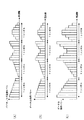
たとえば、図7に示す本実施の形態に対応する方式と図8に示す従来方式とを比較した場合、同じ受信レベル情報に対して(図7(A)と図8(A)参照)、同じ送信電力にもかかわらず(図7(B)と図8(B)参照)、本実施の形態では、図7(C)に示すように、図8(C)に示す従来方式による場合よりも大きい総受信電力を得ることができる。
【0160】
なお、本実施の形態では、MC−CDMA方式におけるサブキャリア逆送信電力制御について説明したが、サブキャリア逆送信電力制御の適用対象方式はこれに限定されるわけではない。たとえば、CDMA方式と組み合わされた任意のマルチキャリア変調方式に適用可能であり、さらには、単なるOFDM方式にも本実施の形態に対応するサブキャリア逆送信電力制御は適用可能である。
【0161】
【発明の効果】
以上説明したように、本発明によれば、MC−CDMA方式において、送信ビット数を保ちつつ、情報の伝送効率および受信性能を向上することができるサブキャリア送信ON/OFF制御方式を実現することができる。
【0162】
また、MC−CDMA方式において、情報の伝送効率および受信性能を向上することができるサブキャリア逆送信電力制御方式を実現することができる。
【0163】
さらに、OFDM方式において、情報の伝送効率および受信性能を向上することができるサブキャリア逆送信電力制御方式を実現することができる。
【図面の簡単な説明】
【図1】本発明の実施の形態1に係るマルチキャリア送信装置およびマルチキャリア受信装置の各構成を示すブロック図
【図2】送信されるOFDM信号の状態を示す図
【図3】OFDM信号におけるサブキャリアの配置の状態を示す図
【図4】本実施の形態に対応するサブキャリア送信ON/OFF制御方式の説明図
【図5】本発明の実施の形態2に係るマルチキャリア送信装置およびマルチキャリア受信装置の各構成を示すブロック図
【図6】本実施の形態に対応するサブキャリア逆送信電力制御方式の説明図
【図7】本実施の形態に対応するサブキャリア逆送信電力制御方式の別の説明図
【図8】従来のサブキャリア送信電力制御方式の説明図
【図9】従来のサブキャリア送信ON/OFF制御方式の説明図
【符号の説明】
100,300 送信機
102 拡散部
104,208 S/P部
106 送信制御部
108 パワー制御部
108a 送信パワー制御部
110 IFFT部
112,214 P/S部
114 GI挿入部
122 ON/OFF情報取り出し部
124 キャリア選択部
200,400 受信機
206 GI除去部
210 FFT部
212 チャネル補償部
216 逆拡散部
218 受信電力検出部
220 ON/OFF情報生成部
302 受信パワー情報取り出し部
304 送信パワー決定部
402 受信パワー情報生成部[0001]
BACKGROUND OF THE INVENTION
The present invention relates to a transmission / reception device, and more particularly to a multicarrier transmission device, a multicarrier reception device, and a multicarrier wireless communication method.
[0002]
[Prior art]
In recent years, in wireless communication, particularly mobile communication, various information such as images and data other than voice has been the object of transmission. In the future, it is expected that the demand for transmission of various contents will become higher, so the need for high-reliability and high-speed transmission is expected to increase further. However, when performing high-speed transmission in mobile communication, the influence of delayed waves due to multipath cannot be ignored, and transmission characteristics deteriorate due to frequency selective fading.
[0003]
As one of frequency selective fading countermeasure techniques, a multicarrier (MC) modulation scheme such as an OFDM (Orthogonal Frequency Division Multiplexing) scheme has attracted attention. The multi-carrier modulation scheme is a technique for performing high-speed transmission as a result by transmitting data using a plurality of carrier waves (subcarriers) whose transmission speed is suppressed to such an extent that frequency selective fading does not occur. In particular, the OFDM scheme has the highest frequency utilization efficiency among the multicarrier modulation schemes because a plurality of subcarriers in which data is arranged are orthogonal to each other, and has a relatively simple hardware configuration. Since it can be realized in the field, it has attracted particular attention and various studies have been added.
[0004]
As an example of such a study, for example, Yoshinori, Sanbe, Morinaga: “Characteristics when Multilevel Transmission Power Control is Applied in OFDM Subcarrier Adaptive Modulation System”, IEICE Technical Report TECHNICAL REPORT OF IEICE. SSE2000-71, RCS2000-60 (2000-07), pp. 63-68, Maeda, Sanbe, Morinaga: “Characteristics of subcarrier transmission power control method using delay profile information channel in OFDM / FDD system”, IEICE Transactions, B, Vol. J84-B, no. 2, pp. 205-213 (February 2001).
[0005]
Here, for example, as shown in FIG. 8, the base station improves the receiver sensitivity by controlling the transmission power so that the reception status for each subcarrier is constant (hereinafter referred to as “conventional method”). 1 ”). Furthermore, for example, as shown in FIG. 9, when performing subcarrier transmission power control, control is performed so that transmission is not performed on subcarriers with low reception quality, thereby reducing transmission power (hereinafter, referred to as “subcarrier transmission power control”). "
[0006]
[Problems to be solved by the invention]
However, the
[0007]
First, in the
[0008]
In particular, in the
[0009]
On the other hand, in the
[0010]
Further, in the
[0011]
Further, in the
[0012]
Recently, as an access method for realizing higher-speed transmission, a method (MC (multi-carrier) -CDMA method or OFDM-CDMA method, which combines the OFDM method and CDMA (Code Division Multiple Access) method, Here, “MC-CDMA system” will be referred to as “MC-CDMA system”. Here, the CDMA system is one of spread spectrum systems, which is another technique for frequency selective fading, and spreads by spreading each user's information directly on the frequency axis with a spreading code unique to each user. This is a technique for improving interference resistance by obtaining gain. The MC-CDMA system will be described in detail later.
[0013]
For example, when the
[0014]
That is, in the
[0015]
In addition, if transmission OFF control is simply performed in the MC-CDMA system, the orthogonality of a transmission signal in which spreading codes are multiplexed is completely broken, and signals transmitted using different spreading codes have exactly the same signal waveform. As a result, the receiving side cannot separate them.
[0016]
The present invention has been made in view of such points, and in the MC-CDMA system, a subcarrier transmission ON / OFF control system that can improve the transmission efficiency and reception performance of information while maintaining the number of transmission bits. An object is to provide a multicarrier transmission apparatus, a multicarrier reception apparatus, and a multicarrier wireless communication method.
[0017]
The present invention also provides a subcarrier transmission power control multicarrier transmission apparatus, multicarrier reception apparatus, and multicarrier radio communication method capable of improving information transmission efficiency and reception performance in MC-CDMA. The purpose is to do.
[0018]
The present invention also provides a subcarrier transmission power control multicarrier transmission apparatus, multicarrier reception apparatus, and multicarrier radio communication method capable of improving information transmission efficiency and reception performance in the OFDM system. With the goal.
[0019]
[Means for Solving the Problems]
(1) The multicarrier transmission apparatus of the present invention is a multicarrier transmission apparatus that performs radio communication by spreading in the frequency axis direction (for example, by the MC-CDMA system), and whether or not transmission power is allocated to each subcarrier. Based on the acquisition presence / absence information acquired by the acquisition means for acquiring allocation presence / absence information on the acquisition means,So that the total transmission power per symbol is constant,And an allocating unit that allocates transmission power for subcarriers without transmission power allocation to subcarriers with transmission power allocation.
[0020]
According to this configuration, for example, in MC-CDMA,So that the total transmission power per symbol is constant,Allocate transmission power for subcarriers without transmission power allocation to subcarriers with transmission power allocation, for example,For each symbolIn order not to transmit subcarriers with low reception quality (transmission OFF) and to allocate the transmission power to other subcarriers with high reception quality for transmission,You can eliminate symbols that are completely transmitted off,Information transmission efficiency can be improved. In addition, at this time, since despreading is performed on the receiving side, position information of subcarriers that are not transmitted is unnecessary.
[0023]
(2)In the multicarrier transmission apparatus of the present invention, in the above configuration, subcarriers to which no transmission power is allocated have the same number (N) as the spreading factor obtained by spreading each symbol in the frequency axis direction with a predetermined spreading factor (N). Among the subcarriers to which the signals of the respective chips are assigned, the number (P) of subcarriers whose reception quality is relatively low for each symbol is a preset number of subcarriers, and the transmission power of the subcarrier to which transmission power is assigned is N / (N−P) The transmission is performed after being multiplied.
[0024]
According to this configuration, since (N−P) subcarriers are always transmitted for each symbol, symbols that are completely transmitted OFF can be eliminated, and the number of transmission bits can be maintained efficiently. Information transmission can be performed. At this time, the transmission power of each subcarrier transmitted per symbol is, for example, a normal N / (N−P) times when evenly distributed.
[0025]
(3)The multicarrier transmission apparatus of the present invention employs a configuration in which the number of subcarriers (P) without transmission power allocation per symbol can be adaptively changed in the above configuration.
[0026]
According to this configuration, the number of subcarriers (P) with no transmission power allocation per symbol is set to an optimal value according to the propagation environment.be able to.
[0027]
(4)In the multicarrier transmission apparatus of the present invention, in the above configuration, the number of subcarriers (P) without transmission power allocation per symbol is expressed by the following equation:
2(NP-1)≧ N
The configuration is set to a value that satisfies
[0028]
According to this configuration, since it is possible to take a combination of N or more types of spreading codes with (N−P) subcarriers, it is possible to avoid signals spread with different spreading codes from having the same waveform. Then, it is possible to always separate signals of different spreading codes.
[0029]
(5)In the multicarrier transmission apparatus according to the present invention, in the above configuration, the acquisition unit receives reception quality information related to reception quality for each subcarrier estimated on the reception side, and reception received by the reception unit. And determining means for determining the allocation presence / absence information based on quality information.
[0030]
According to this configuration, the allocation presence / absence information can be determined on the transmission side, and the amount of calculation on the reception side can be reduced.
[0031]
(6)The multicarrier transmission apparatus of the present invention employs a configuration in which, in the above configuration, the acquisition unit includes a reception unit that receives the allocation presence / absence information determined on the reception side.
[0032]
According to this configuration, allocation presence / absence information can be determined on the receiving side, and the allocation presence / absence information has a smaller amount of information than the reception quality information for each subcarrier, so the information amount from the receiving side to the transmission side is reduced. be able to.
[0033]
(7)In the multicarrier transmission apparatus according to the present invention, in the above configuration, the acquisition unit uses a first estimation unit that estimates a delay profile of a received signal and a delay profile estimated by the first estimation unit for each subcarrier. The second estimation means for estimating the reception quality information related to the reception quality of the receiver and the determination means for determining the allocation presence / absence information based on the reception quality information estimated by the second estimation means.
[0034]
According to this configuration, the reception quality information for each subcarrier for transmission ON / OFF control is estimated from the reception side to the transmission side using the fact that the delay profiles are almost the same between the uplink and the downlink. Feedback signal (assignment presence / absence information or reception quality information for each subcarrier) becomes unnecessary, and the assignment presence / absence information can be determined only on the transmission side.
[0035]
(8)The multicarrier receiver of the present invention is the above-mentioned(5)A multicarrier reception apparatus that performs radio communication with the multicarrier transmission apparatus described above, wherein estimation means for estimating reception quality information related to reception quality for each subcarrier, and transmission for transmitting reception quality information estimated by the estimation means And a configuration having the means.
[0036]
According to this configuration, the allocation presence / absence information can be determined based on the reception quality information for each subcarrier on the transmission side, and the amount of calculation on the reception side can be reduced.
[0037]
(9)The multicarrier receiver of the present invention is the above-mentioned(6)A multicarrier receiver that performs wireless communication with the multicarrier transmitter described above, based on estimation means that estimates reception quality information related to reception quality for each subcarrier, and reception quality information estimated by the estimation means, A configuration is adopted that includes a determination unit that determines allocation presence / absence information regarding the presence / absence of transmission power allocation to each subcarrier, and a transmission unit that transmits the allocation presence / absence information determined by the determination unit.
[0038]
According to this configuration, since the allocation presence / absence information has a smaller amount of information than the reception quality information for each subcarrier, the allocation side presence / absence information is determined on the reception side, so the information amount from the reception side to the transmission side can be reduced. it can.
[0039]
(10)The base station apparatus of the present invention is the above (1) to (1)(7)The multicarrier transmission apparatus according to any one of the above is employed.
[0040]
According to this configuration, it is possible to provide a base station apparatus having the same function and effect as described above.
[0041]
(11)The mobile station apparatus of the present invention is the above(8)Or(9)A configuration having the described multicarrier receiver is adopted.
[0042]
According to this configuration, it is possible to provide a mobile station apparatus having the same operational effects as described above.
[0043]
(12)The mobile station apparatus according to the present invention is the above (1) to (1).(7)The multicarrier transmission apparatus according to any one of the above is employed.
[0044]
According to this configuration, it is possible to provide a mobile station apparatus having the same operational effects as described above.
[0045]
(13)The base station apparatus of the present invention is the above(8)Or(9)A configuration having the described multicarrier receiver is adopted.
[0046]
According to this configuration, it is possible to provide a base station apparatus having the same function and effect as described above.
[0047]
(14)The multicarrier radio communication method of the present invention is a multicarrier radio communication method in a multicarrier transmission apparatus that performs radio communication by spreading in the frequency axis direction (for example, by the MC-CDMA method), and transmitting to each subcarrier. Based on the acquisition step of acquiring allocation presence / absence information regarding the presence / absence of power allocation, and the allocation presence / absence information acquired in the acquisition step,So that the total transmission power per symbol is constant,An allocation step of allocating transmission power for subcarriers without transmission power allocation to subcarriers with transmission power allocation.
[0048]
According to this method, for example, in MC-CDMA,So that the total transmission power per symbol is constant,Allocate transmission power for subcarriers without transmission power allocation to subcarriers with transmission power allocation, for example,For each symbolIn order not to transmit subcarriers with low reception quality (transmission OFF) and to allocate the transmission power to other subcarriers with high reception quality for transmission,You can eliminate symbols that are completely transmitted off,Information transmission efficiency can be improved. In addition, at this time, since despreading is performed on the receiving side, position information of subcarriers that are not transmitted is unnecessary.
[0051]
(15)In the multicarrier radio communication method of the present invention, the number of subcarriers to which no transmission power is allocated is equal to the spreading factor obtained by spreading each symbol in the frequency axis direction with a predetermined spreading factor (N) (N ) Of sub-carriers to which the signals of the chips are assigned, the number (P) of sub-carriers having a relatively low reception quality for each symbol, and the transmission power of the sub-carriers with transmission power allocation is N / (N−P) times the transmission.
[0052]
According to this method, since (N−P) subcarriers are always transmitted for each symbol, symbols that are completely transmitted OFF can be eliminated, and the number of transmission bits can be maintained efficiently. Information transmission can be performed. At this time, the transmission power of each subcarrier transmitted per symbol is, for example, a normal N / (N−P) times when evenly distributed.
[0053]
(16)In the multicarrier radio communication method of the present invention, in the above method, the number of subcarriers (P) without transmission power allocation per symbol can be adaptively changed.
[0054]
According to this method, the number of subcarriers (P) without transmission power allocation per symbol is set to an optimum value according to the propagation environment.be able to.
[0055]
(17)In the multicarrier wireless communication method of the present invention, in the above method, the number of subcarriers (P) without transmission power allocation per symbol is expressed by the following equation:
2(NP-1)≧ N
It was set to a value that satisfies
[0056]
According to this method, since it is possible to take a combination of N or more types of spreading codes with (N−P) subcarriers, it is possible to avoid signals spread with different spreading codes from having the same waveform. Then, it is possible to always separate signals of different spreading codes.
[0057]
(18)In the multicarrier radio communication method of the present invention, in the above method, the acquisition step includes a reception step of receiving reception quality information related to reception quality for each subcarrier estimated on the reception side, and a reception received in the reception step. And a determination step for determining the allocation presence / absence information based on quality information.
[0058]
According to this method, allocation presence / absence information can be determined on the transmission side, and the amount of computation on the reception side can be reduced.
[0059]
(19)In the multicarrier radio communication method of the present invention, in the above method, the acquisition step includes a reception step of receiving the allocation presence / absence information determined on the reception side.
[0060]
According to this method, allocation presence / absence information can be determined on the receiving side, and the allocation presence / absence information has a smaller amount of information than the reception quality information for each subcarrier, so the amount of information from the receiving side to the transmission side is reduced. be able to.
[0061]
(20)In the multicarrier radio communication method of the present invention, in the above method, the obtaining step includes: a first estimation step for estimating a delay profile of a received signal; and a delay profile estimated in the first estimation step for each subcarrier. A second estimation step for estimating reception quality information related to the reception quality, and a determination step for determining the allocation presence / absence information based on the reception quality information estimated in the second estimation step.
[0062]
According to this method, the reception quality information for each subcarrier for transmission ON / OFF control is estimated from the reception side to the transmission side using the fact that the delay profiles are almost the same between the uplink and the downlink. Feedback signal (assignment presence / absence information or reception quality information for each subcarrier) becomes unnecessary, and the assignment presence / absence information can be determined only on the transmission side.
[0063]
(21)The multi-carrier wireless communication method of the present invention is the above-mentioned(18)An estimation step of estimating reception quality information related to reception quality for each subcarrier, in a multicarrier wireless communication method in a multicarrier reception apparatus that performs wireless communication with a multicarrier transmission apparatus that uses the described multicarrier wireless communication method; A transmission step of transmitting the reception quality information estimated in the estimation step.
[0064]
According to this method, allocation presence / absence information can be determined based on reception quality information for each subcarrier on the transmission side, and the amount of computation on the reception side can be reduced.
[0065]
(22)The multi-carrier wireless communication method of the present invention is the above-mentioned(19)An estimation step of estimating reception quality information related to reception quality for each subcarrier, in a multicarrier wireless communication method in a multicarrier reception apparatus that performs wireless communication with a multicarrier transmission apparatus that uses the described multicarrier wireless communication method; Based on the reception quality information estimated in the estimation step, a determination step of determining allocation presence / absence information regarding the presence / absence of transmission power allocation for each subcarrier, and a transmission step of transmitting the allocation presence / absence information determined in the determination step. To have.
[0066]
According to this method, since the allocation presence / absence information has a smaller information amount than the reception quality information for each subcarrier, the allocation side presence / absence information is determined on the reception side, so the information amount from the reception side to the transmission side can be reduced. it can.
[0067]
(23)The multicarrier transmission apparatus according to the present invention is a multicarrier transmission apparatus that performs radio communication by spreading in the frequency axis direction (for example, by the MC-CDMA system), and performs reception related to the reception level of each subcarrier on the reception side. Based on the acquisition means for acquiring level information and the reception level information acquired by the acquisition means,So that the total transmission power per symbol is constant,And a control unit that controls the transmission power of each subcarrier so that the transmission power of the subcarrier with a higher reception level is higher and the transmission power of the subcarrier with a lower reception level is lower.
[0068]
According to this configuration, for example, in the MC-CDMA system, according to the reception level of each subcarrier on the reception side,So that the total transmission power per symbol is constant,Because subcarriers with higher reception levels transmit with higher transmission power and subcarriers with lower reception levels transmit with lower transmission power,While controlling the transmission power per symbol as usual,It is possible to efficiently amplify the signal in the propagation path and receive the signal, and to improve information transmission efficiency and reception performance.
[0071]
(24)The multicarrier receiver of the present invention is the above-mentioned(23)A multicarrier receiving apparatus that performs radio communication with the multicarrier transmitting apparatus described above, wherein the detecting means detects reception level information relating to the reception level of each subcarrier, and transmission that transmits the reception quality information detected by the detecting means And a configuration having the means.
[0072]
According to this configuration, reception level information of each subcarrier necessary for subcarrier transmission power control on the transmission side can be detected on the reception side and provided to the transmission side.
[0073]
(25)The base station apparatus of the present invention is the above(23)A configuration having the described multicarrier transmission apparatus is adopted.
[0074]
According to this configuration, it is possible to provide a base station apparatus having the same function and effect as described above.
[0075]
(26)The mobile station apparatus of the present invention is the above(24)A configuration having the described multicarrier receiver is adopted.
[0076]
According to this configuration, it is possible to provide a mobile station apparatus having the same operational effects as described above.
[0077]
(27)The mobile station apparatus of the present invention is the above(23)A configuration having the described multicarrier transmission apparatus is adopted.
[0078]
According to this configuration, it is possible to provide a mobile station apparatus having the same operational effects as described above.
[0079]
(28)The base station apparatus of the present invention is the above(24)A configuration having the described multicarrier receiver is adopted.
[0080]
According to this configuration, it is possible to provide a base station apparatus having the same function and effect as described above.
[0081]
(29)The multicarrier radio communication method of the present invention is a multicarrier radio communication method in a multicarrier transmission apparatus that performs radio communication by spreading in the frequency axis direction (for example, by the MC-CDMA system), Based on the acquisition step of acquiring the reception level information regarding the reception level of the subcarrier, and the reception level information acquired in the acquisition step,So that the total transmission power per symbol is constant,And a control step for controlling the transmission power of each subcarrier so that the transmission power is higher for subcarriers with higher reception levels and transmission power is lower for subcarriers with lower reception levels.
[0082]
According to this method, for example, in the MC-CDMA system, according to the reception level of each subcarrier on the reception side,So that the total transmission power per symbol is constant,Because subcarriers with higher reception levels transmit with higher transmission power and subcarriers with lower reception levels transmit with lower transmission power,While controlling the transmission power per symbol as usual,It is possible to efficiently amplify the signal in the propagation path and receive the signal, and to improve information transmission efficiency and reception performance.
[0085]
(30)The multi-carrier wireless communication method of the present invention is the above-mentioned(29)A multicarrier radio communication method in a multicarrier reception apparatus that performs radio communication with a multicarrier transmission apparatus that uses the described multicarrier radio communication method, wherein the detection step detects reception level information related to the reception level of each subcarrier; A transmission step of transmitting the reception quality information detected in the detection step.
[0086]
According to this method, in the MC-CDMA system, reception level information of each subcarrier necessary for subcarrier transmission power control on the transmission side can be detected and provided to the transmission side.
[0087]
(31)The multicarrier transmission apparatus of the present invention is a multicarrier transmission apparatus that performs radio communication by the OFDM method, and obtains reception level information related to the reception level of each subcarrier on the reception side, and obtainment by the acquisition means Based on received reception level informationSo that the total transmission power per symbol is constant,And a control unit that controls the transmission power of each subcarrier so that the transmission power of the subcarrier with a higher reception level is higher and the transmission power of the subcarrier with a lower reception level is lower.
[0088]
According to this configuration, in the OFDM scheme, according to the reception level of each subcarrier on the reception side,So that the total transmission power per symbol is constant,Because subcarriers with higher reception levels transmit with higher transmission power and subcarriers with lower reception levels transmit with lower transmission power,While controlling the transmission power per symbol as usual,It is possible to efficiently amplify the signal in the propagation path and receive the signal, and to improve information transmission efficiency and reception performance.
[0091]
(32)The multicarrier receiver of the present invention is the above-mentioned(31)A multicarrier receiving apparatus that performs radio communication with the multicarrier transmitting apparatus described above, wherein the detecting means detects reception level information relating to the reception level of each subcarrier, and transmission that transmits the reception quality information detected by the detecting means And a configuration having the means.
[0092]
According to this configuration, reception level information of each subcarrier necessary for subcarrier transmission power control on the transmission side can be detected on the reception side and provided to the transmission side.
[0093]
(33)The base station apparatus of the present invention is the above(31)A configuration having the described multicarrier transmission apparatus is adopted.
[0094]
According to this configuration, it is possible to provide a base station apparatus having the same function and effect as described above.
[0095]
(34)The mobile station apparatus of the present invention is the above(32)A configuration having the described multicarrier receiver is adopted.
[0096]
According to this configuration, it is possible to provide a mobile station apparatus having the same operational effects as described above.
[0097]
(35)The mobile station apparatus of the present invention is the above(31)A configuration having the described multicarrier transmission apparatus is adopted.
[0098]
According to this configuration, it is possible to provide a mobile station apparatus having the same operational effects as described above.
[0099]
(36)The base station apparatus of the present invention is the above(32)A configuration having the described multicarrier receiver is adopted.
[0100]
According to this configuration, it is possible to provide a base station apparatus having the same function and effect as described above.
[0101]
(37)The multicarrier radio communication method of the present invention is a multicarrier radio communication method in a multicarrier transmission apparatus that performs radio communication by the OFDM method, and obtains reception level information related to the reception level of each subcarrier on the receiving side. And based on the reception level information acquired in the acquisition step,So that the total transmission power per symbol is constant,And a control step for controlling the transmission power of each subcarrier so that the transmission power is higher for subcarriers with higher reception levels and transmission power is lower for subcarriers with lower reception levels.
[0102]
According to this method, in the OFDM scheme, according to the reception level of each subcarrier on the reception side,So that the total transmission power per symbol is constant,Because subcarriers with higher reception levels transmit with higher transmission power and subcarriers with lower reception levels transmit with lower transmission power,While controlling the transmission power per symbol as usual,It is possible to efficiently amplify the signal in the propagation path and receive the signal, and to improve information transmission efficiency and reception performance.
[0105]
(38)The multi-carrier wireless communication method of the present invention is the above-mentioned(37)A multicarrier radio communication method in a multicarrier reception apparatus that performs radio communication with a multicarrier transmission apparatus that uses the described multicarrier radio communication method, wherein the detection step detects reception level information related to the reception level of each subcarrier; A transmission step of transmitting the reception quality information detected in the detection step.
[0106]
According to this method, in the OFDM scheme, reception level information of each subcarrier necessary for subcarrier transmission power control on the transmission side can be detected on the reception side and provided to the transmission side.
(39) The multicarrier transmission apparatus of the present invention employs a configuration in which the number of subcarriers (P) without transmission power allocation per symbol is transmitted to the receiving side in the above configuration.
According to this configuration, in the case where the allocation presence / absence information is determined on the reception side, the number of subcarriers (P) without transmission power allocation per symbol is transmitted from the transmission side to the reception side. It is possible to recognize that the power of the subcarrier is multiplied by N / (N−P). For example, since the reference level for QAM demodulation can be recognized, QAM demodulation can be performed.
(40) In the multicarrier radio communication method of the present invention, in the above method, the number of subcarriers (P) without transmission power allocation per symbol is transmitted to the receiving side.
According to this method, when determining the allocation presence / absence information on the receiving side, the number of subcarriers (P) without transmission power allocation per symbol is transmitted from the transmitting side to the receiving side. It is possible to recognize that the power of the subcarrier is multiplied by N / (N−P). For example, since the reference level for QAM demodulation can be recognized, QAM demodulation can be performed.
(41) In the multicarrier receiver of the present invention, in the above configuration, the reception level information indicates a relative reception level of one symbol section obtained by normalizing the reception level of each subcarrier over one symbol section. Take the structure that is information.
According to this configuration, since the reception level information is information indicating the relative reception level of one symbol section, the dynamic range of the notification information can be reduced, that is, the number of bits necessary for information transmission can be reduced. .
(42) In the multicarrier wireless communication method of the present invention, in the above method, the reception level information includes a relative reception level of one symbol section obtained by normalizing a reception level of each subcarrier over one symbol section. The information is shown.
According to this method, since the reception level information is information indicating the relative reception level of one symbol section, the dynamic range of the notification information can be reduced, that is, the number of bits necessary for information transmission can be reduced. .
[0107]
DETAILED DESCRIPTION OF THE INVENTION
The essence of the present invention is the MC-CDMA system,While keeping the total transmission power per symbol constant,Transmission of subcarriers with low reception quality and no transmission power allocation is not performed (transmission OFF), and the corresponding transmission power is allocated to a subcarrier with transmission power allocation (transmission ON) for transmission (subcarrier) Transmission ON / OFF control). Also, in the MC-CDMA scheme or OFDM scheme, depending on the reception level of each subcarrier on the receiving side,While keeping the total transmission power per symbol constant,The transmission is performed by increasing the transmission power as the subcarrier has a higher reception level, and the transmission is performed by decreasing the transmission power as the subcarrier has a lower reception level (subcarrier reverse transmission power control).
[0108]
Hereinafter, embodiments of the present invention will be described in detail with reference to the drawings.
[0109]
(Embodiment 1)
FIG. 1 is a block diagram showing configurations of a multicarrier transmission apparatus and a multicarrier reception apparatus according to
[0110]
1 includes a spreading
[0111]
1 includes a transmission / reception shared
[0112]
The
[0113]
Here, the contents of the MC-CDMA system will be described with reference to FIGS.
[0114]
In the MC-CDMA system, a signal is distributed and transmitted to a plurality of (for example, 512) carrier waves (subcarriers). Specifically, the transmission signal is first spread in the frequency axis direction by a spreading code and code-multiplexed. The code-multiplexed signal is serial / parallel converted into parallel signals for the number of subcarriers. FIG. 2 shows the state of the transmitted OFDM signal (n is the number of subcarriers). In the figure, “1” is a guard interval, “3” is a chip, and “5” is an OFDM symbol. In the example of FIG. 2, data of 4 symbols is transmitted after being spread n times. Each symbol is spread over n chips in the frequency axis direction. Note that the number of subcarriers and the number of spreading codes do not necessarily match. Although not shown, a pilot signal (known signal) is arranged for each subcarrier in the OFDM signal.
[0115]
In the MC-CDMA system, each subcarrier is OFDM-modulated so as to be an orthogonal signal. The parallel signal after the serial / parallel conversion is transmitted through IFFT processing. By the IFFT processing, the OFDM signal can maintain a state in which the signals are orthogonal between the subcarriers as shown in FIG. Here, the signals being orthogonal means that the spectrum of a signal of a certain subcarrier does not affect signals of other frequencies. When performing OFDM modulation, a guard interval is inserted into the OFDM symbol. By inserting a guard interval, orthogonality can be maintained when there is only a delayed wave shorter than the guard interval length.
[0116]
Next, operations of
[0117]
In
[0118]
The S /
[0119]
The
[0120]
[0121]
The P /
[0122]
The
[0123]
The signal after the insertion of the guard interval is subjected to predetermined radio processing such as amplifier conversion in the
[0124]
Thereafter, the
[0125]
The
[0126]
The
[0127]
S /
[0128]
In
[0129]
At this time, first,
[0130]
P /
[0131]
[0132]
On the other hand, reception
[0133]
The ON / OFF
[0134]
Thus, in this Embodiment, the subcarrier with relatively low reception quality is selected. For example, in the example shown in FIG. 4A,
[0135]
At this time, the value of P is expressed by the following
2(NP-1)≧ N (Formula 1)
Is set to a value that satisfies As a result, since it is possible to take a combination of N or more types of spreading codes with (N−P) subcarriers, signals spread with different spreading codes are avoided from having the same waveform, and different spreading is performed on the receiving side. The code signal can always be separated.
[0136]
For example, in the case of quadruple diffusion (N = 4), 2(4-P-1)P satisfying ≧ 4 is P <2, so P = 1, and only one transmission can be turned OFF.
[0137]
Specifically, first, consider the case where the transmission of two subcarriers is turned off in the case of quadruple spreading. At this time, in quadruple spreading, there are four codes 1111, 1100, 1001, and 1010. When transmission of two subcarriers is turned off, these four codes are −−11 and −−00, respectively. , -01, and -10. Therefore, the signal obtained by spreading the signal “1” by the
[0138]
On the other hand, let us consider a case where only one subcarrier is turned off in the case of quadruple spreading. At this time, in quadruple spreading, there are four codes 1111, 1100, 1001, and 1010. When transmission of one subcarrier is turned off, these four codes are -111, -100,-, respectively. 001 and -010. Therefore, any of the total 8 including -000, -011, -110, and -101 obtained by inverting these four codes is not the same as each other. The data is never the same signal. Therefore, when N = 4, P <2 is an essential condition.
[0139]
An output signal (transmission ON / OFF information for each subcarrier) of the ON / OFF
[0140]
Thereafter, the
[0141]
The
[0142]
The ON / OFF
[0143]
As described above, according to the present embodiment, in the MC-CDMA system, transmission of subcarriers with low reception quality and no transmission power allocation is not performed (transmission OFF), and the corresponding transmission power is transmitted to the
[0144]
In the present embodiment, transmission ON / OFF information for each subcarrier is determined by
[0145]
Furthermore, using the fact that the delay profile is almost the same between upstream and downstream, the transmitter uses the delay profile information of the received signal from the receiver for each subcarrier for transmission ON / OFF control. Reception quality information may be estimated, and transmission ON / OFF information for each subcarrier may be determined. In this case, a feedback signal (transmission ON / OFF information for each subcarrier or reception quality information for each subcarrier) from the receiver to the transmitter becomes unnecessary, and transmission ON / OFF information for each subcarrier can be obtained by the transmitter alone. Can be determined.
[0146]
In this embodiment, the P value used in the ON / OFF
[0147]
In the present embodiment,
[0148]
In this embodiment, the case where the present invention is applied to the MC-CDMA system has been described. However, the present invention is not limited to this, and the present invention can be applied to any multicarrier modulation system combined with the CDMA system. Applicable.
[0149]
(Embodiment 2)
FIG. 5 is a block diagram showing each configuration of the multicarrier transmission apparatus and the multicarrier reception apparatus according to
[0150]
A feature of the present embodiment is that subcarrier transmission power control (herein referred to as “subcarrier reverse transmission power control”) is performed in a mode opposite to that of the
[0151]
Also in this case, the
[0152]
Next, characteristic operations of the
[0153]
In accordance with the notification from the
[0154]
In the conventional method, in order to compensate for power fluctuations in the propagation path (see FIG. 8C), the transmission power of the subcarrier is controlled to be a
[0155]
On the other hand, the
[0156]
Reception power
[0157]
At this time, the received power may be normalized over one symbol section, and information indicating the relative power state of one symbol section may be notified. That is, when the spreading factor is N, the standardized power information Hknorm is expressed by the
[0158]
Thus, according to the present embodiment, in the MC-CDMA scheme, the total value of the transmission power of all subcarriers per symbol in accordance with the reception level (reception power) of each subcarrier at
[0159]
For example, when the method corresponding to the present embodiment shown in FIG. 7 is compared with the conventional method shown in FIG. 8, the same reception level information (see FIGS. 7A and 8A) is the same. Regardless of the transmission power (see FIGS. 7B and 8B), in this embodiment, as shown in FIG. 7C, compared to the case of the conventional method shown in FIG. 8C. A large total received power can be obtained.
[0160]
In addition, although this Embodiment demonstrated subcarrier reverse transmission power control in MC-CDMA system, the application object system of subcarrier reverse transmission power control is not necessarily limited to this. For example, the present invention can be applied to an arbitrary multicarrier modulation scheme combined with a CDMA scheme, and further, subcarrier reverse transmission power control corresponding to this embodiment can be applied to a simple OFDM scheme.
[0161]
【The invention's effect】
As described above, according to the present invention, in the MC-CDMA system, it is possible to realize a subcarrier transmission ON / OFF control system capable of improving the transmission efficiency and reception performance of information while maintaining the number of transmission bits. Can do.
[0162]
Also, in the MC-CDMA system, it is possible to realize a subcarrier reverse transmission power control system that can improve the transmission efficiency and reception performance of information.
[0163]
Furthermore, in the OFDM scheme, it is possible to realize a subcarrier reverse transmission power control scheme that can improve information transmission efficiency and reception performance.
[Brief description of the drawings]
FIG. 1 is a block diagram showing configurations of a multicarrier transmission apparatus and a multicarrier reception apparatus according to
FIG. 2 is a diagram showing a state of a transmitted OFDM signal
FIG. 3 is a diagram showing a state of subcarrier arrangement in an OFDM signal
FIG. 4 is an explanatory diagram of a subcarrier transmission ON / OFF control method corresponding to the present embodiment
FIG. 5 is a block diagram showing configurations of a multicarrier transmission apparatus and a multicarrier reception apparatus according to
FIG. 6 is an explanatory diagram of a subcarrier reverse transmission power control method corresponding to the present embodiment
FIG. 7 is another explanatory diagram of a subcarrier reverse transmission power control method corresponding to the present embodiment.
FIG. 8 is an explanatory diagram of a conventional subcarrier transmission power control method
FIG. 9 is an explanatory diagram of a conventional subcarrier transmission ON / OFF control method.
[Explanation of symbols]
100,300 transmitter
102 Diffusion part
104,208 S / P part
106 Transmission control unit
108 Power control unit
108a Transmission power control unit
110 IFFT section
112,214 P / S part
114 GI insertion part
122 ON / OFF information extraction unit
124 Carrier selection part
200,400 receiver
206 GI removal unit
210 FFT section
212 Channel Compensator
216 Despreading part
218 Received power detector
220 ON / OFF information generator
302 Received power information extraction unit
304 Transmission power determination unit
402 Received power information generation unit
Claims (34)
各サブキャリアに対する送信電力割り当ての有無に関する割り当て有無情報を取得する取得手段と、
前記取得手段によって取得された割り当て有無情報を基に、1シンボル当たりの送信電力の合計値が一定になるように、送信電力割り当てのないサブキャリア分の送信電力を送信電力の割り当てのあるサブキャリアに割り当てる割り当て手段と、を有し、
前記送信電力割り当てのないサブキャリアは、各シンボルを所定の拡散率(N)で周波数軸方向に拡散して得られる拡散率と同数(N)のチップの信号がそれぞれ割り当てられたサブキャリアのうち、シンボルごとに相対的に受信品質が低いあらかじめ設定された数(P)のサブキャリアであり、前記送信電力割り当てのあるサブキャリアの送信電力はN/(N−P)倍されて送信される、
ことを特徴とするマルチキャリア送信装置。A multicarrier transmission apparatus that performs wireless communication by spreading in the frequency axis direction,
Acquisition means for acquiring allocation presence / absence information regarding the presence / absence of transmission power allocation for each subcarrier;
Based on the allocation presence / absence information acquired by the acquisition means, the transmission power for subcarriers without transmission power allocation is subcarriers with transmission power allocation so that the total transmission power per symbol is constant. anda means for assigning to,
The subcarriers without transmission power allocation are subcarriers to which signals of the same number (N) of chips as the spreading factor obtained by spreading each symbol in the frequency axis direction with a predetermined spreading factor (N) are assigned. , A predetermined number (P) of subcarriers having relatively low reception quality for each symbol, and the transmission power of the subcarrier with the transmission power allocation is multiplied by N / (N−P) and transmitted. ,
A multicarrier transmission apparatus characterized by the above.
2(N−P−1)≧N
ことを特徴とする請求項1記載のマルチキャリア送信装置。The number of subcarriers without transmission power allocation per symbol (P) is set to a value that satisfies the following equation:
2 (N-P-1) ≧ N
The multicarrier transmission apparatus according to claim 1 .
受信側で推定されたサブキャリアごとの受信品質に関する受信品質情報を受信する受信手段と、
前記受信手段によって受信された受信品質情報を基に、前記割り当て有無情報を決定する決定手段と、
を有することを特徴とする請求項1記載のマルチキャリア送信装置。The acquisition means includes
Receiving means for receiving reception quality information related to reception quality for each subcarrier estimated on the receiving side;
Determining means for determining the allocation presence / absence information based on the reception quality information received by the receiving means;
The multicarrier transmission apparatus according to claim 1, comprising:
受信側で決定された前記割り当て有無情報を受信する受信手段、
を有することを特徴とする請求項1記載のマルチキャリア送信装置。The acquisition means includes
Receiving means for receiving the allocation presence / absence information determined on the receiving side;
The multicarrier transmission apparatus according to claim 1, comprising:
受信信号の遅延プロファイルを推定する第1推定手段と、
前記第1推定手段によって推定された遅延プロファイルを用いてサブキャリアごとの受信品質に関する受信品質情報を推定する第2推定手段と、
前記第2推定手段によって推定された受信品質情報を基に、前記割り当て有無情報を決定する決定手段と、
を有することを特徴とする請求項1記載のマルチキャリア送信装置。The acquisition means includes
First estimating means for estimating a delay profile of a received signal;
Second estimation means for estimating reception quality information related to reception quality for each subcarrier using the delay profile estimated by the first estimation means;
Determination means for determining the allocation presence / absence information based on the reception quality information estimated by the second estimation means;
The multicarrier transmission apparatus according to claim 1, comprising:
サブキャリアごとの受信品質に関する受信品質情報を推定する推定手段と、
前記推定手段によって推定された受信品質情報を送信する送信手段と、
を有することを特徴とするマルチキャリア受信装置。A multicarrier receiver that performs radio communication with the multicarrier transmitter according to claim 5,
An estimation means for estimating reception quality information related to reception quality for each subcarrier;
Transmitting means for transmitting the reception quality information estimated by the estimating means;
A multi-carrier receiver characterized by comprising:
サブキャリアごとの受信品質に関する受信品質情報を推定する推定手段と、
前記推定手段によって推定された受信品質情報を基に、各サブキャリアに対する送信電力割り当ての有無に関する割り当て有無情報を決定する決定手段と、
前記決定手段によって決定された割り当て有無情報を送信する送信手段と、
を有することを特徴とするマルチキャリア受信装置。A multicarrier receiver that performs radio communication with the multicarrier transmitter according to claim 6,
An estimation means for estimating reception quality information related to reception quality for each subcarrier;
A determination unit that determines allocation presence / absence information related to the presence / absence of transmission power allocation for each subcarrier based on the reception quality information estimated by the estimation unit;
Transmitting means for transmitting allocation presence / absence information determined by the determining means;
A multi-carrier receiver characterized by comprising:
各サブキャリアに対する送信電力割り当ての有無に関する割り当て有無情報を取得する取得ステップと、
前記取得ステップで取得した割り当て有無情報を基に、1シンボル当たりの送信電力の合計値が一定になるように、送信電力割り当てのないサブキャリア分の送信電力を送信電力の割り当てのあるサブキャリアに割り当てる割り当てステップと、を有し、
前記送信電力割り当てのないサブキャリアは、各シンボルを所定の拡散率(N)で周波数軸方向に拡散して得られる拡散率と同数(N)のチップの信号がそれぞれ割り当てられたサブキャリアのうち、シンボルごとに相対的に受信品質が低いあらかじめ設定された数(P)のサブキャリアであり、前記送信電力割り当てのあるサブキャリアの送信電力はN/(N−P)倍されて送信される、
ことを特徴とするマルチキャリア無線通信方法。A multi-carrier wireless communication method in a multi-carrier transmission apparatus for performing wireless communication by spreading in the frequency axis direction,
An acquisition step of acquiring allocation presence / absence information regarding the presence / absence of transmission power allocation for each subcarrier;
Based on the allocation presence / absence information acquired in the acquisition step, transmission power for subcarriers without transmission power allocation is assigned to subcarriers with transmission power allocation so that the total transmission power per symbol is constant. An assigning step ,
The subcarriers without transmission power allocation are subcarriers to which signals of the same number (N) of chips as the spreading factor obtained by spreading each symbol in the frequency axis direction with a predetermined spreading factor (N) are assigned. , A predetermined number (P) of subcarriers having relatively low reception quality for each symbol, and the transmission power of the subcarrier with the transmission power allocation is multiplied by N / (N−P) and transmitted. ,
A multi-carrier wireless communication method.
2(N−P−1)≧N
ことを特徴とする請求項14記載のマルチキャリア無線通信方法。The number of subcarriers without transmission power allocation per symbol (P) is set to a value that satisfies the following equation:
2 (N-P-1) ≧ N
The multicarrier radio communication method according to claim 14 .
受信側で推定されたサブキャリアごとの受信品質に関する受信品質情報を受信する受信ステップと、
前記受信ステップで受信した受信品質情報を基に、前記割り当て有無情報を決定する決定ステップと、
を有することを特徴とする請求項14記載のマルチキャリア無線通信方法。The obtaining step includes
A reception step of receiving reception quality information related to reception quality for each subcarrier estimated on the reception side;
A determination step of determining the allocation presence / absence information based on the reception quality information received in the reception step;
15. The multicarrier wireless communication method according to claim 14, further comprising:
受信側で決定された前記割り当て有無情報を受信する受信ステップ、
を有することを特徴とする請求項14記載のマルチキャリア無線通信方法。The obtaining step includes
A receiving step of receiving the allocation presence / absence information determined on the receiving side;
15. The multicarrier wireless communication method according to claim 14, further comprising:
受信信号の遅延プロファイルを推定する第1推定ステップと、
前記第1推定ステップで推定した遅延プロファイルを用いてサブキャリアごとの受信品質に関する受信品質情報を推定する第2推定ステップと、
前記第2推定ステップで推定した受信品質情報を基に、前記割り当て有無情報を決定する決定ステップと、
を有することを特徴とする請求項14記載のマルチキャリア無線通信方法。The obtaining step includes
A first estimation step for estimating a delay profile of the received signal;
A second estimation step for estimating reception quality information related to reception quality for each subcarrier using the delay profile estimated in the first estimation step;
A determination step for determining the allocation presence / absence information based on the reception quality information estimated in the second estimation step;
15. The multicarrier wireless communication method according to claim 14, further comprising:
サブキャリアごとの受信品質に関する受信品質情報を推定する推定ステップと、
前記推定ステップで推定した受信品質情報を送信する送信ステップと、
を有することを特徴とするマルチキャリア無線通信方法。A multicarrier radio communication method in a multicarrier reception apparatus that performs radio communication with a multicarrier transmission apparatus that uses the multicarrier radio communication method according to claim 18,
An estimation step for estimating reception quality information related to reception quality for each subcarrier;
A transmission step of transmitting the reception quality information estimated in the estimation step;
A multi-carrier wireless communication method comprising:
サブキャリアごとの受信品質に関する受信品質情報を推定する推定ステップと、
前記推定ステップで推定した受信品質情報を基に、各サブキャリアに対する送信電力割り当ての有無に関する割り当て有無情報を決定する決定ステップと、
前記決定ステップで決定した割り当て有無情報を送信する送信ステップと、
を有することを特徴とするマルチキャリア無線通信方法。A multicarrier radio communication method in a multicarrier receiver that performs radio communication with a multicarrier transmitter that uses the multicarrier radio communication method according to claim 19,
An estimation step for estimating reception quality information related to reception quality for each subcarrier;
Based on the reception quality information estimated in the estimation step, a determination step for determining allocation presence / absence information regarding the presence / absence of transmission power allocation for each subcarrier;
A transmission step of transmitting the allocation presence / absence information determined in the determination step;
A multi-carrier wireless communication method comprising:
各サブキャリアの受信レベルに関する受信レベル情報を検出する検出手段と、
前記検出手段によって検出された受信レベル情報を送信する送信手段と、を有し、
前記受信レベル情報は、各サブキャリアの受信レベルを1シンボル区間にわたって規格化して得られる1シンボル区間の相対的な受信レベルを示す情報である、
ことを特徴とするマルチキャリア受信装置。 A multicarrier transmission apparatus that performs radio communication by spreading in the frequency axis direction, an acquisition unit that acquires reception level information regarding a reception level of each subcarrier on a reception side, and a reception level acquired by the acquisition unit Based on the information, each subcarrier has a subcarrier with a higher reception level such that the transmission power is higher and a subcarrier with a lower reception level has a lower transmission power so that the total transmission power per symbol is constant. A multicarrier transmission apparatus for performing wireless communication with a multicarrier transmission apparatus having a control means for controlling the transmission power of
Detection means for detecting reception level information relating to the reception level of each subcarrier;
Anda transmitting means for transmitting the reception level information detected by said detecting means,
The reception level information is information indicating a relative reception level of one symbol section obtained by normalizing the reception level of each subcarrier over one symbol section.
A multicarrier receiver characterized by that.
各サブキャリアの受信レベルに関する受信レベル情報を検出する検出ステップと、
前記検出ステップで検出した受信レベル情報を送信する送信ステップと、を有し、
前記受信レベル情報は、各サブキャリアの受信レベルを1シンボル区間にわたって規格化して得られる1シンボル区間の相対的な受信レベルを示す情報である、
ことを特徴とするマルチキャリア無線通信方法。 A multicarrier transmission apparatus that performs radio communication by spreading in the frequency axis direction, an acquisition step of acquiring reception level information regarding the reception level of each subcarrier on the reception side, and the reception level information acquired in the acquisition step Based on the above, in order to keep the total transmission power per symbol constant, subcarriers with higher reception levels have higher transmission power, and subcarriers with lower reception levels have lower transmission power. A multicarrier radio communication method in a multicarrier reception apparatus that performs radio communication with a multicarrier transmission apparatus using a multicarrier radio communication method having a control step for controlling transmission power ,
A detection step of detecting reception level information regarding the reception level of each subcarrier;
Anda transmission step of transmitting the reception level information detected by the detecting step,
The reception level information is information indicating a relative reception level of one symbol section obtained by normalizing the reception level of each subcarrier over one symbol section.
A multi-carrier wireless communication method.
前記マルチキャリア送信装置は、 The multi-carrier transmission apparatus includes:
受信側での各サブキャリアの受信レベルに関する受信レベル情報を受信する受信手段と、 Receiving means for receiving reception level information on the reception level of each subcarrier on the receiving side;
前記受信手段によって受信された受信レベル情報を基に、1シンボル当たりの送信電力の合計値が一定になるように、受信レベルが高いサブキャリアほど送信電力が大きく受信レベルが低いサブキャリアほど送信電力が小さくなるように、各サブキャリアの送信電力を制御する制御手段と、を有し、 Based on the reception level information received by the receiving means, a subcarrier with a higher reception level has a higher transmission power and a transmission power with a lower reception level so that the total value of transmission power per symbol is constant. Control means for controlling the transmission power of each subcarrier so that the
前記マルチキャリア受信装置は、 The multicarrier receiver is
各サブキャリアの受信レベルに関する受信レベル情報を検出する検出手段と、 Detection means for detecting reception level information relating to the reception level of each subcarrier;
前記検出手段によって検出された受信レベル情報を送信する送信手段と、を有し、 Transmission means for transmitting the reception level information detected by the detection means,
前記受信レベル情報は、各サブキャリアの受信レベルを1シンボル区間にわたって規格化して得られる1シンボル区間の相対的な受信レベルを示す情報である、 The reception level information is information indicating a relative reception level of one symbol section obtained by normalizing the reception level of each subcarrier over one symbol section.
ことを特徴とするマルチキャリア通信システム。 A multi-carrier communication system.
前記マルチキャリア送信装置が、受信側での各サブキャリアの受信レベルに関する受信レベル情報を受信する受信ステップと、 A reception step in which the multicarrier transmission apparatus receives reception level information regarding the reception level of each subcarrier on the reception side;
前記マルチキャリア送信装置が、前記受信ステップで受信した受信レベル情報を基に、1シンボル当たりの送信電力の合計値が一定になるように、受信レベルが高いサブキャリアほど送信電力が大きく受信レベルが低いサブキャリアほど送信電力が小さくなるように、各サブキャリアの送信電力を制御する制御ステップと、 Based on the reception level information received in the reception step, the multicarrier transmission apparatus has a higher transmission power and a higher reception level for subcarriers with higher reception levels so that the total transmission power per symbol is constant. A control step for controlling the transmission power of each subcarrier so that the transmission power is lower as the subcarrier is lower;
前記マルチキャリア受信装置が、各サブキャリアの受信レベルに関する受信レベル情報を検出する検出ステップと、 A detection step in which the multicarrier receiving apparatus detects reception level information related to a reception level of each subcarrier; and
前記マルチキャリア受信装置が、前記検出ステップで検出した受信レベル情報を送信する送信ステップと、を有し、 The multicarrier receiving apparatus has a transmission step of transmitting the reception level information detected in the detection step;
前記受信レベル情報は、各サブキャリアの受信レベルを1シンボル区間にわたって規格化して得られる1シンボル区間の相対的な受信レベルを示す情報である、 The reception level information is information indicating a relative reception level of one symbol section obtained by normalizing the reception level of each subcarrier over one symbol section.
ことを特徴とするマルチキャリア無線通信方法。 A multi-carrier wireless communication method.
各サブキャリアの受信レベルに関する受信レベル情報を検出する検出手段と、
前記検出手段によって検出された受信レベル情報を送信する送信手段と、を有し、
前記受信レベル情報は、各サブキャリアの受信レベルを1シンボル区間にわたって規格化して得られる1シンボル区間の相対的な受信レベルを示す情報である、
ことを特徴とするマルチキャリア受信装置。 A multi-carrier transmission apparatus that performs radio communication using the OFDM method, on the basis of the reception level information acquired by the acquisition unit that acquires reception level information related to the reception level of each subcarrier on the reception side, Control the transmission power of each subcarrier so that the subcarrier with a higher reception level has a higher transmission power and the transmission power with a lower reception level has a lower transmission power so that the total transmission power per symbol is constant. A multi-carrier receiving apparatus for performing wireless communication with a multi -carrier transmitting apparatus having control means for performing
Detection means for detecting reception level information relating to the reception level of each subcarrier;
Anda transmitting means for transmitting the reception level information detected by said detecting means,
The reception level information is information indicating a relative reception level of one symbol section obtained by normalizing the reception level of each subcarrier over one symbol section.
A multicarrier receiver characterized by that.
各サブキャリアの受信レベルに関する受信レベル情報を検出する検出ステップと、
前記検出ステップで検出した受信レベル情報を送信する送信ステップと、を有し、
前記受信レベル情報は、各サブキャリアの受信レベルを1シンボル区間にわたって規格化して得られる1シンボル区間の相対的な受信レベルを示す情報である、
ことを特徴とするマルチキャリア無線通信方法。 A multi-carrier transmission apparatus that performs radio communication using an OFDM method, based on an acquisition step of acquiring reception level information regarding the reception level of each subcarrier on the reception side, and the reception level information acquired in the acquisition step The transmission power of each subcarrier is controlled so that the transmission power is higher for subcarriers with higher reception levels and the transmission power is lower for subcarriers with lower reception levels so that the total transmission power per symbol is constant. A multi-carrier radio communication method in a multi-carrier receiver that performs radio communication with a multi-carrier transmitter that uses a multi-carrier radio communication method having a control step ,
A detection step of detecting reception level information regarding the reception level of each subcarrier;
Anda transmission step of transmitting the reception level information detected by the detecting step,
The reception level information is information indicating a relative reception level of one symbol section obtained by normalizing the reception level of each subcarrier over one symbol section.
A multi-carrier wireless communication method.
前記マルチキャリア送信装置は、 The multi-carrier transmission apparatus includes:
受信側での各サブキャリアの受信レベルに関する受信レベル情報を受信する受信手段と、 Receiving means for receiving reception level information on the reception level of each subcarrier on the receiving side;
前記受信手段によって受信された受信レベル情報を基に、1シンボル当たりの送信電力の合計値が一定になるように、受信レベルが高いサブキャリアほど送信電力が大きく受信レベルが低いサブキャリアほど送信電力が小さくなるように、各サブキャリアの送信電力を制御する制御手段と、を有し、 Based on the reception level information received by the receiving means, a subcarrier with a higher reception level has a higher transmission power and a transmission power with a lower reception level so that the total value of transmission power per symbol is constant. Control means for controlling the transmission power of each subcarrier so that the
前記マルチキャリア受信装置は、 The multicarrier receiver is
各サブキャリアの受信レベルに関する受信レベル情報を検出する検出手段と、 Detection means for detecting reception level information relating to the reception level of each subcarrier;
前記検出手段によって検出された受信レベル情報を送信する送信手段と、を有し、 Transmission means for transmitting the reception level information detected by the detection means,
前記受信レベル情報は、各サブキャリアの受信レベルを1シンボル区間にわたって規格化して得られる1シンボル区間の相対的な受信レベルを示す情報である、 The reception level information is information indicating a relative reception level of one symbol section obtained by normalizing the reception level of each subcarrier over one symbol section.
ことを特徴とするマルチキャリア通信システム。 A multi-carrier communication system.
前記マルチキャリア送信装置が、受信側での各サブキャリアの受信レベルに関する受信レベル情報を受信する受信ステップと、 A reception step in which the multicarrier transmission apparatus receives reception level information regarding the reception level of each subcarrier on the reception side;
前記マルチキャリア送信装置が、前記受信ステップで受信した受信レベル情報を基に、1シンボル当たりの送信電力の合計値が一定になるように、受信レベルが高いサブキャリアほど送信電力が大きく受信レベルが低いサブキャリアほど送信電力が小さくなるように、各サブキャリアの送信電力を制御する制御ステップと、 Based on the reception level information received in the reception step, the multicarrier transmission apparatus has a higher transmission power and a higher reception level for subcarriers with higher reception levels so that the total transmission power per symbol is constant. A control step for controlling the transmission power of each subcarrier so that the transmission power is lower as the subcarrier is lower;
前記マルチキャリア受信装置が、各サブキャリアの受信レベルに関する受信レベル情報を検出する検出ステップと、 A detection step in which the multicarrier receiving apparatus detects reception level information related to a reception level of each subcarrier; and
前記マルチキャリア受信装置が、前記検出ステップで検出した受信レベル情報を送信する送信ステップと、を有し、 The multicarrier receiving apparatus has a transmission step of transmitting the reception level information detected in the detection step;
前記受信レベル情報は、各サブキャリアの受信レベルを1シンボル区間にわたって規格化して得られる1シンボル区間の相対的な受信レベルを示す情報である、 The reception level information is information indicating a relative reception level of one symbol section obtained by normalizing the reception level of each subcarrier over one symbol section.
ことを特徴とするマルチキャリア無線通信方法。 A multi-carrier wireless communication method.
Priority Applications (5)
| Application Number | Priority Date | Filing Date | Title |
|---|---|---|---|
| JP2001214545A JP3607643B2 (en) | 2001-07-13 | 2001-07-13 | Multicarrier transmission apparatus, multicarrier reception apparatus, and multicarrier radio communication method |
| PCT/JP2002/006712 WO2003009504A1 (en) | 2001-07-13 | 2002-07-03 | Multi-carrier transmission apparatus, multi-carrier reception apparatus, and multi-carrier radio communication method |
| EP02743785.4A EP1411664B1 (en) | 2001-07-13 | 2002-07-03 | Multi-carrier transmission apparatus, multi-carrier reception apparatus, and multi-carrier radio communication method |
| US10/380,222 US7200177B2 (en) | 2001-07-13 | 2002-07-03 | Multi-carrier transmission apparatus, multi-carrier reception apparatus, and multi-carrier radio communication method |
| CNB028026373A CN1278504C (en) | 2001-07-13 | 2002-07-03 | Multi-carrier transmitting device, multi-carrier receiving device and multi-carrier wireless communication method |
Applications Claiming Priority (1)
| Application Number | Priority Date | Filing Date | Title |
|---|---|---|---|
| JP2001214545A JP3607643B2 (en) | 2001-07-13 | 2001-07-13 | Multicarrier transmission apparatus, multicarrier reception apparatus, and multicarrier radio communication method |
Publications (2)
| Publication Number | Publication Date |
|---|---|
| JP2003032218A JP2003032218A (en) | 2003-01-31 |
| JP3607643B2 true JP3607643B2 (en) | 2005-01-05 |
Family
ID=19049340
Family Applications (1)
| Application Number | Title | Priority Date | Filing Date |
|---|---|---|---|
| JP2001214545A Expired - Fee Related JP3607643B2 (en) | 2001-07-13 | 2001-07-13 | Multicarrier transmission apparatus, multicarrier reception apparatus, and multicarrier radio communication method |
Country Status (5)
| Country | Link |
|---|---|
| US (1) | US7200177B2 (en) |
| EP (1) | EP1411664B1 (en) |
| JP (1) | JP3607643B2 (en) |
| CN (1) | CN1278504C (en) |
| WO (1) | WO2003009504A1 (en) |
Families Citing this family (135)
| Publication number | Priority date | Publication date | Assignee | Title |
|---|---|---|---|---|
| WO2000035397A1 (en) * | 1998-12-18 | 2000-06-22 | Kimberly-Clark Worldwide, Inc. | Absorbent articles having hinged fasteners |
| US9130810B2 (en) | 2000-09-13 | 2015-09-08 | Qualcomm Incorporated | OFDM communications methods and apparatus |
| US7295509B2 (en) | 2000-09-13 | 2007-11-13 | Qualcomm, Incorporated | Signaling method in an OFDM multiple access system |
| US20050105593A1 (en) * | 2002-10-07 | 2005-05-19 | Takashi Dateki | Transmission power control method and transmission power control apparatus in OFDM-CDMA |
| JP4109556B2 (en) * | 2003-01-31 | 2008-07-02 | 松下電器産業株式会社 | OFDM signal collision position detection apparatus, OFDM reception apparatus, OFDM signal collision position detection method, and OFDM reception method |
| US8081598B2 (en) | 2003-02-18 | 2011-12-20 | Qualcomm Incorporated | Outer-loop power control for wireless communication systems |
| US8391249B2 (en) | 2003-02-18 | 2013-03-05 | Qualcomm Incorporated | Code division multiplexing commands on a code division multiplexed channel |
| US8150407B2 (en) | 2003-02-18 | 2012-04-03 | Qualcomm Incorporated | System and method for scheduling transmissions in a wireless communication system |
| US7155236B2 (en) | 2003-02-18 | 2006-12-26 | Qualcomm Incorporated | Scheduled and autonomous transmission and acknowledgement |
| US20040160922A1 (en) | 2003-02-18 | 2004-08-19 | Sanjiv Nanda | Method and apparatus for controlling data rate of a reverse link in a communication system |
| US8023950B2 (en) | 2003-02-18 | 2011-09-20 | Qualcomm Incorporated | Systems and methods for using selectable frame durations in a wireless communication system |
| US8705588B2 (en) | 2003-03-06 | 2014-04-22 | Qualcomm Incorporated | Systems and methods for using code space in spread-spectrum communications |
| US7215930B2 (en) | 2003-03-06 | 2007-05-08 | Qualcomm, Incorporated | Method and apparatus for providing uplink signal-to-noise ratio (SNR) estimation in a wireless communication |
| KR100531851B1 (en) * | 2003-03-06 | 2005-11-30 | 엘지전자 주식회사 | Data transmission and reception method for mobile communication system |
| US7012912B2 (en) * | 2003-05-14 | 2006-03-14 | Qualcomm Incorporated | Power control and scheduling in an OFDM system |
| US8477592B2 (en) | 2003-05-14 | 2013-07-02 | Qualcomm Incorporated | Interference and noise estimation in an OFDM system |
| JP2005045504A (en) * | 2003-07-28 | 2005-02-17 | Toshiba Corp | Multi-carrier communication system, multi-carrier receiver and multi-carrier transmitter |
| US8489949B2 (en) | 2003-08-05 | 2013-07-16 | Qualcomm Incorporated | Combining grant, acknowledgement, and rate control commands |
| EP2600540B1 (en) | 2003-08-06 | 2018-12-12 | Optis Wireless Technology, LLC | Wireless communication apparatus and wireless communication method |
| JP3877215B2 (en) * | 2003-10-10 | 2007-02-07 | 株式会社インテリジェント・コスモス研究機構 | Transmission device, communication system, and communication method |
| KR100557158B1 (en) * | 2003-11-12 | 2006-03-03 | 삼성전자주식회사 | Apparatus and Method for Subcarrier Allocation in Mobile Communication System Using Orthogonal Frequency Division Multiplexing |
| KR100996080B1 (en) * | 2003-11-19 | 2010-11-22 | 삼성전자주식회사 | Apparatus and Method for Adaptive Modulation and Coding Control in Communication System Using Orthogonal Frequency Division Multiplexing |
| US8090857B2 (en) | 2003-11-24 | 2012-01-03 | Qualcomm Atheros, Inc. | Medium access control layer that encapsulates data from a plurality of received data units into a plurality of independently transmittable blocks |
| US7315563B2 (en) * | 2003-12-03 | 2008-01-01 | Ut-Battelle Llc | Multicarrier orthogonal spread-spectrum (MOSS) data communications |
| WO2005109705A1 (en) * | 2004-05-01 | 2005-11-17 | Neocific, Inc. | Methods and apparatus for communication with time-division duplexing |
| US7826435B1 (en) * | 2004-03-05 | 2010-11-02 | Zte (Usa) Inc. | Power control in OFDM and OFDMA wireless communication networks |
| WO2005086729A2 (en) * | 2004-03-05 | 2005-09-22 | Nextnet Wireless, Inc. | System and method for adaptive modulation |
| KR100689379B1 (en) * | 2004-04-14 | 2007-03-02 | 삼성전자주식회사 | Method and apparatus for transmitting uplink control information in orthogonal frequency division multiple access communication system |
| US7142107B2 (en) | 2004-05-27 | 2006-11-28 | Lawrence Kates | Wireless sensor unit |
| US7197692B2 (en) | 2004-06-18 | 2007-03-27 | Qualcomm Incorporated | Robust erasure detection and erasure-rate-based closed loop power control |
| US7594151B2 (en) | 2004-06-18 | 2009-09-22 | Qualcomm, Incorporated | Reverse link power control in an orthogonal system |
| US8452316B2 (en) | 2004-06-18 | 2013-05-28 | Qualcomm Incorporated | Power control for a wireless communication system utilizing orthogonal multiplexing |
| CN1973492B (en) * | 2004-06-24 | 2010-12-08 | 皇家飞利浦电子股份有限公司 | Method for transmitting status of subcarriers in MC network and method for adaptively allocating subcarriers in MC network |
| US7778369B2 (en) | 2004-07-06 | 2010-08-17 | Panasonic Corporation | Multi-carrier transmission device and multi-carrier transmission method |
| US9148256B2 (en) | 2004-07-21 | 2015-09-29 | Qualcomm Incorporated | Performance based rank prediction for MIMO design |
| US9137822B2 (en) | 2004-07-21 | 2015-09-15 | Qualcomm Incorporated | Efficient signaling over access channel |
| JP4892349B2 (en) * | 2004-07-30 | 2012-03-07 | パナソニック株式会社 | Base station apparatus and radio communication method |
| CN1993953B (en) * | 2004-08-05 | 2011-01-26 | 松下电器产业株式会社 | Wireless transmission device and wireless transmission method |
| US8081688B2 (en) | 2004-08-06 | 2011-12-20 | Panasonic Corporation | Radio transmitting apparatus and radio transmitting method in multicarrier communication |
| US20070298728A1 (en) * | 2004-09-10 | 2007-12-27 | Matsushita Electric Industrial Co. Ltd. | Wireless Communication Apparatus and Wireless Communication Method |
| JP4658959B2 (en) | 2004-10-29 | 2011-03-23 | シャープ株式会社 | Communication method and wireless transmitter |
| KR100790115B1 (en) | 2004-10-29 | 2007-12-31 | 삼성전자주식회사 | Apparatus and method for controlling preamble sequence transmit power for adaptive antenna system in communication system |
| CN100384190C (en) * | 2005-01-07 | 2008-04-23 | 北京邮电大学 | A Bit and Power Allocation Algorithm for Adaptive Modulation in MC-CDMA System |
| EP1841112B1 (en) * | 2005-01-18 | 2014-06-04 | Fujitsu Limited | Transmitting method and transmitting apparatus in ofdm-cdma communication system |
| CN103731924B (en) | 2005-01-18 | 2017-03-01 | 夏普株式会社 | Dispensing device and reception device |
| US20060203794A1 (en) * | 2005-03-10 | 2006-09-14 | Qualcomm Incorporated | Systems and methods for beamforming in multi-input multi-output communication systems |
| US9246560B2 (en) | 2005-03-10 | 2016-01-26 | Qualcomm Incorporated | Systems and methods for beamforming and rate control in a multi-input multi-output communication systems |
| US9154211B2 (en) | 2005-03-11 | 2015-10-06 | Qualcomm Incorporated | Systems and methods for beamforming feedback in multi antenna communication systems |
| US8942639B2 (en) | 2005-03-15 | 2015-01-27 | Qualcomm Incorporated | Interference control in a wireless communication system |
| US8848574B2 (en) | 2005-03-15 | 2014-09-30 | Qualcomm Incorporated | Interference control in a wireless communication system |
| US7512412B2 (en) * | 2005-03-15 | 2009-03-31 | Qualcomm, Incorporated | Power control and overlapping control for a quasi-orthogonal communication system |
| US8446892B2 (en) | 2005-03-16 | 2013-05-21 | Qualcomm Incorporated | Channel structures for a quasi-orthogonal multiple-access communication system |
| US20090213950A1 (en) * | 2005-03-17 | 2009-08-27 | Qualcomm Incorporated | Pilot signal transmission for an orthogonal frequency division wireless communication system |
| US9461859B2 (en) | 2005-03-17 | 2016-10-04 | Qualcomm Incorporated | Pilot signal transmission for an orthogonal frequency division wireless communication system |
| US9520972B2 (en) | 2005-03-17 | 2016-12-13 | Qualcomm Incorporated | Pilot signal transmission for an orthogonal frequency division wireless communication system |
| US9143305B2 (en) | 2005-03-17 | 2015-09-22 | Qualcomm Incorporated | Pilot signal transmission for an orthogonal frequency division wireless communication system |
| US7881741B2 (en) * | 2005-03-18 | 2011-02-01 | Panasonic Corporation | Mobile station apparatus and wireless communication method |
| US9184870B2 (en) | 2005-04-01 | 2015-11-10 | Qualcomm Incorporated | Systems and methods for control channel signaling |
| JPWO2006114932A1 (en) * | 2005-04-18 | 2008-12-11 | シャープ株式会社 | Wireless communication apparatus and wireless communication method |
| US9036538B2 (en) | 2005-04-19 | 2015-05-19 | Qualcomm Incorporated | Frequency hopping design for single carrier FDMA systems |
| US9408220B2 (en) | 2005-04-19 | 2016-08-02 | Qualcomm Incorporated | Channel quality reporting for adaptive sectorization |
| US20060245390A1 (en) * | 2005-04-28 | 2006-11-02 | Yukihiro Omoto | Base station and mobile station constituting mobile communication system |
| US20060262874A1 (en) * | 2005-05-17 | 2006-11-23 | Interdigital Technology Corporation | Method and apparatus for power control in a multiple antenna system |
| EP1879306A1 (en) * | 2005-05-26 | 2008-01-16 | Matsushita Electric Industrial Co., Ltd. | Wireless communication base station apparatus and wireless communication method |
| US8611284B2 (en) | 2005-05-31 | 2013-12-17 | Qualcomm Incorporated | Use of supplemental assignments to decrement resources |
| US8879511B2 (en) | 2005-10-27 | 2014-11-04 | Qualcomm Incorporated | Assignment acknowledgement for a wireless communication system |
| US8565194B2 (en) | 2005-10-27 | 2013-10-22 | Qualcomm Incorporated | Puncturing signaling channel for a wireless communication system |
| US8462859B2 (en) | 2005-06-01 | 2013-06-11 | Qualcomm Incorporated | Sphere decoding apparatus |
| US8599945B2 (en) | 2005-06-16 | 2013-12-03 | Qualcomm Incorporated | Robust rank prediction for a MIMO system |
| US9179319B2 (en) | 2005-06-16 | 2015-11-03 | Qualcomm Incorporated | Adaptive sectorization in cellular systems |
| US8670493B2 (en) | 2005-06-22 | 2014-03-11 | Eices Research, Inc. | Systems and/or methods of increased privacy wireless communications |
| US8660095B2 (en) | 2005-07-21 | 2014-02-25 | Qualcomm Incorporated | Reverse link transmit power control in a wireless communication system |
| US8175190B2 (en) * | 2005-07-27 | 2012-05-08 | Qualcomm Atheros, Inc. | Managing spectra of modulated signals in a communication network |
| US8885628B2 (en) | 2005-08-08 | 2014-11-11 | Qualcomm Incorporated | Code division multiplexing in a single-carrier frequency division multiple access system |
| US9209956B2 (en) | 2005-08-22 | 2015-12-08 | Qualcomm Incorporated | Segment sensitive scheduling |
| US20070041457A1 (en) | 2005-08-22 | 2007-02-22 | Tamer Kadous | Method and apparatus for providing antenna diversity in a wireless communication system |
| US8644292B2 (en) | 2005-08-24 | 2014-02-04 | Qualcomm Incorporated | Varied transmission time intervals for wireless communication system |
| US20070047495A1 (en) * | 2005-08-29 | 2007-03-01 | Qualcomm Incorporated | Reverse link soft handoff in a wireless multiple-access communication system |
| US9136974B2 (en) | 2005-08-30 | 2015-09-15 | Qualcomm Incorporated | Precoding and SDMA support |
| US9225416B2 (en) | 2005-10-27 | 2015-12-29 | Qualcomm Incorporated | Varied signaling channels for a reverse link in a wireless communication system |
| US9144060B2 (en) | 2005-10-27 | 2015-09-22 | Qualcomm Incorporated | Resource allocation for shared signaling channels |
| US8582509B2 (en) | 2005-10-27 | 2013-11-12 | Qualcomm Incorporated | Scalable frequency band operation in wireless communication systems |
| US9225488B2 (en) | 2005-10-27 | 2015-12-29 | Qualcomm Incorporated | Shared signaling channel |
| US9210651B2 (en) | 2005-10-27 | 2015-12-08 | Qualcomm Incorporated | Method and apparatus for bootstraping information in a communication system |
| US8693405B2 (en) | 2005-10-27 | 2014-04-08 | Qualcomm Incorporated | SDMA resource management |
| US8477684B2 (en) | 2005-10-27 | 2013-07-02 | Qualcomm Incorporated | Acknowledgement of control messages in a wireless communication system |
| US8045512B2 (en) | 2005-10-27 | 2011-10-25 | Qualcomm Incorporated | Scalable frequency band operation in wireless communication systems |
| US9088384B2 (en) | 2005-10-27 | 2015-07-21 | Qualcomm Incorporated | Pilot symbol transmission in wireless communication systems |
| US9172453B2 (en) | 2005-10-27 | 2015-10-27 | Qualcomm Incorporated | Method and apparatus for pre-coding frequency division duplexing system |
| WO2007050926A2 (en) | 2005-10-27 | 2007-05-03 | Qualcomm Incorporated | Method and apparatus for estimating reverse link loading in a wireless communication system |
| WO2007055619A1 (en) * | 2005-11-09 | 2007-05-18 | Telefonaktiebolaget L M Ericsson (Publ) | Selection of radio resources in a radio communications network |
| US8582548B2 (en) | 2005-11-18 | 2013-11-12 | Qualcomm Incorporated | Frequency division multiple access schemes for wireless communication |
| US8831607B2 (en) | 2006-01-05 | 2014-09-09 | Qualcomm Incorporated | Reverse link other sector communication |
| AU2007252363B2 (en) * | 2006-05-19 | 2009-10-01 | Lg Electronics Inc. | A method of utilizing and manipulating wireless resources for efficient and effective wireless communication |
| US7826548B2 (en) * | 2006-05-19 | 2010-11-02 | Lg Electronics, Inc. | Resource management in a wireless communication network |
| JP4952088B2 (en) * | 2006-06-23 | 2012-06-13 | ソニー株式会社 | TRANSMISSION DEVICE, TRANSMISSION METHOD, RECEPTION DEVICE, RECEPTION METHOD, AND TRANSMISSION SYSTEM |
| JP4769656B2 (en) * | 2006-07-28 | 2011-09-07 | 京セラ株式会社 | Wireless communication method and wireless communication terminal |
| JP4769657B2 (en) * | 2006-07-28 | 2011-09-07 | 京セラ株式会社 | Wireless communication method and wireless communication terminal |
| US7649951B2 (en) | 2006-08-16 | 2010-01-19 | Harris Corporation | System and method for communicating data using symbol-based randomized orthogonal frequency division multiplexing (OFDM) with applied frequency domain spreading |
| US7813433B2 (en) * | 2006-08-16 | 2010-10-12 | Harris Corporation | System and method for communicating data using symbol-based randomized orthogonal frequency division multiplexing (OFDM) with selected subcarriers turned on or off |
| US7751488B2 (en) * | 2006-08-16 | 2010-07-06 | Harris Corporation | System and method for communicating data using symbol-based randomized orthogonal frequency division multiplexing (OFDM) |
| US7903749B2 (en) * | 2006-08-16 | 2011-03-08 | Harris Corporation | System and method for applying frequency domain spreading to multi-carrier communications signals |
| US7860147B2 (en) * | 2006-08-16 | 2010-12-28 | Harris Corporation | Method of communicating and associated transmitter using coded orthogonal frequency division multiplexing (COFDM) |
| US8670777B2 (en) | 2006-09-08 | 2014-03-11 | Qualcomm Incorporated | Method and apparatus for fast other sector interference (OSI) adjustment |
| US8442572B2 (en) | 2006-09-08 | 2013-05-14 | Qualcomm Incorporated | Method and apparatus for adjustments for delta-based power control in wireless communication systems |
| JP4930006B2 (en) * | 2006-11-22 | 2012-05-09 | 日本電気株式会社 | Mobile communication apparatus, mobile communication system, and power consumption reduction method used therefor |
| EP1928115A1 (en) * | 2006-11-30 | 2008-06-04 | Nokia Siemens Networks Gmbh & Co. Kg | Adaptive modulation and coding in a SC-FDMA system |
| US7904021B2 (en) * | 2006-12-21 | 2011-03-08 | Atheros Communications, Inc. | Selecting carriers for modulating signals in a communication network |
| JP4640844B2 (en) * | 2007-01-09 | 2011-03-02 | 株式会社エヌ・ティ・ティ・ドコモ | Transmission device, transmission method, and communication system |
| EP2117146B1 (en) | 2007-02-28 | 2016-04-13 | NTT DoCoMo, Inc. | Base station device, user device, and method used in mobile communication system |
| CN101772906B (en) * | 2007-08-03 | 2013-06-05 | 富士通株式会社 | Transmission power control method of wireless base station and wireless base station |
| JP4548487B2 (en) * | 2008-01-11 | 2010-09-22 | ソニー株式会社 | Transmission device, communication system, transmission method, and program |
| US8565146B2 (en) * | 2008-02-27 | 2013-10-22 | Qualcomm Incorporated | Method and apparatus for supporting data transmission in a multi-carrier communication system |
| WO2009148253A2 (en) | 2008-06-02 | 2009-12-10 | 고려대학교 산학협력단 | Supporting substrate for fabrication of semiconductor light emitting device and semiconductor light emitting device using the same |
| US20110134879A1 (en) * | 2008-08-05 | 2011-06-09 | Panasonic Corporation | Wireless communication device and power density setting method |
| US9042479B2 (en) * | 2008-10-16 | 2015-05-26 | Qualcomm Incorporated | Method and apparatus for avoiding interference between coexisting wireless systems |
| JP5293079B2 (en) * | 2008-10-23 | 2013-09-18 | 株式会社日立製作所 | Wireless communication system and transmission power and data rate control method thereof |
| JP2010136233A (en) * | 2008-12-08 | 2010-06-17 | Mitsubishi Electric Corp | Multi-carrier transmitter/receiver apparatus and method of multi-carrier transmitting/receiving |
| RU2496266C2 (en) * | 2009-04-27 | 2013-10-20 | Хуавэй Текнолоджиз Ко., Лтд. | Power control apparatus and method |
| WO2011082145A2 (en) * | 2010-01-04 | 2011-07-07 | Atheros Communications, Inc. | Transmit power control |
| JP4675432B2 (en) * | 2010-08-31 | 2011-04-20 | 株式会社エヌ・ティ・ティ・ドコモ | Receiving apparatus and receiving method for receiving transmission signal modulated by OFDM method |
| US8817802B2 (en) * | 2011-12-21 | 2014-08-26 | Comtech Ef Data Corp. | Method and system for providing hitless switching while maintaining a power equivalent bandwidth (PEB) ratio using multiple carriers |
| CN104067586B (en) * | 2012-01-30 | 2018-02-09 | 马维尔国际贸易有限公司 | System and method for generating the leading code sign in communication system |
| US8781008B2 (en) * | 2012-06-20 | 2014-07-15 | MagnaCom Ltd. | Highly-spectrally-efficient transmission using orthogonal frequency division multiplexing |
| US8559494B1 (en) | 2012-06-20 | 2013-10-15 | MagnaCom Ltd. | Timing synchronization for reception of highly-spectrally-efficient communications |
| US8737458B2 (en) | 2012-06-20 | 2014-05-27 | MagnaCom Ltd. | Highly-spectrally-efficient reception using orthogonal frequency division multiplexing |
| US9118519B2 (en) | 2013-11-01 | 2015-08-25 | MagnaCom Ltd. | Reception of inter-symbol-correlated signals using symbol-by-symbol soft-output demodulator |
| US9130637B2 (en) | 2014-01-21 | 2015-09-08 | MagnaCom Ltd. | Communication methods and systems for nonlinear multi-user environments |
| US9496900B2 (en) | 2014-05-06 | 2016-11-15 | MagnaCom Ltd. | Signal acquisition in a multimode environment |
| US8891701B1 (en) | 2014-06-06 | 2014-11-18 | MagnaCom Ltd. | Nonlinearity compensation for reception of OFDM signals |
| US10791924B2 (en) | 2014-08-10 | 2020-10-06 | Autonomix Medical, Inc. | ANS assessment systems, kits, and methods |
| US9246523B1 (en) | 2014-08-27 | 2016-01-26 | MagnaCom Ltd. | Transmitter signal shaping |
| US9191247B1 (en) | 2014-12-09 | 2015-11-17 | MagnaCom Ltd. | High-performance sequence estimation system and method of operation |
| KR101988406B1 (en) | 2015-06-26 | 2019-06-12 | 스카이워크스 솔루션즈, 인코포레이티드 | Power detection of individual carrier of aggregated carrier |
| US10142073B2 (en) * | 2016-08-05 | 2018-11-27 | Panasonic Corporation | Terminal apparatus, radio communication system and communication method |
Family Cites Families (10)
| Publication number | Priority date | Publication date | Assignee | Title |
|---|---|---|---|---|
| KR0155818B1 (en) * | 1995-04-29 | 1998-11-16 | 김광호 | Adaptive Power Distribution Method and Apparatus in Multicarrier Transmission System |
| US5852633A (en) * | 1996-06-07 | 1998-12-22 | Motorola, Inc. | Method for allocating data in a data communication system |
| JPH1168630A (en) * | 1997-08-19 | 1999-03-09 | Yuseisho Tsushin Sogo Kenkyusho | Propagation path distortion compensating method |
| JP2911861B2 (en) | 1997-11-26 | 1999-06-23 | 株式会社次世代デジタルテレビジョン放送システム研究所 | OFDM receiver |
| US6275522B1 (en) * | 1998-01-14 | 2001-08-14 | Motorola, Inc. | Method for allocating data and power in a discrete, multi-tone communication system |
| EP0930752A3 (en) | 1998-01-14 | 1999-10-20 | Motorola, Inc. | Method for allocating data and power in a discrete multitone communication system |
| US7039120B1 (en) * | 1998-11-30 | 2006-05-02 | Canon Kabushiki Kaisha | Device and method for the dynamic allocation of frequencies for multicarrier modulation systems |
| JP3191802B2 (en) | 1999-06-17 | 2001-07-23 | 三菱電機株式会社 | Communication device and communication method |
| JP3581281B2 (en) | 1999-11-11 | 2004-10-27 | 松下電器産業株式会社 | OFDM-CDMA receiving apparatus and OFDM-CDMA transmitting apparatus |
| US6721569B1 (en) * | 2000-09-29 | 2004-04-13 | Nortel Networks Limited | Dynamic sub-carrier assignment in OFDM systems |
-
2001
- 2001-07-13 JP JP2001214545A patent/JP3607643B2/en not_active Expired - Fee Related
-
2002
- 2002-07-03 EP EP02743785.4A patent/EP1411664B1/en not_active Expired - Lifetime
- 2002-07-03 WO PCT/JP2002/006712 patent/WO2003009504A1/en not_active Ceased
- 2002-07-03 CN CNB028026373A patent/CN1278504C/en not_active Expired - Fee Related
- 2002-07-03 US US10/380,222 patent/US7200177B2/en not_active Expired - Lifetime
Also Published As
| Publication number | Publication date |
|---|---|
| CN1278504C (en) | 2006-10-04 |
| JP2003032218A (en) | 2003-01-31 |
| WO2003009504A1 (en) | 2003-01-30 |
| EP1411664B1 (en) | 2016-08-31 |
| CN1465153A (en) | 2003-12-31 |
| EP1411664A1 (en) | 2004-04-21 |
| US7200177B2 (en) | 2007-04-03 |
| EP1411664A4 (en) | 2009-12-30 |
| US20040009783A1 (en) | 2004-01-15 |
Similar Documents
| Publication | Publication Date | Title |
|---|---|---|
| JP3607643B2 (en) | Multicarrier transmission apparatus, multicarrier reception apparatus, and multicarrier radio communication method | |
| JP4046712B2 (en) | Subcarrier allocation apparatus and method in orthogonal frequency division multiplexing system | |
| US7852746B2 (en) | Transmission of signaling in an OFDM-based system | |
| US7852959B2 (en) | Method of transmitting control signal in wireless communication system | |
| EP1492280B1 (en) | Quality driven adaptive channel assignment in an OFDMA radio communication system | |
| CN102064848B (en) | Method and apparatus for movable station and base station in a multi-subzones broadband wireless system | |
| US8385933B2 (en) | Base station device and radio communication device | |
| CN1951033B (en) | Method and device for overlapping multi-carrier and direct sequence spread spectrum signals in broadband wireless communication system | |
| US8817753B2 (en) | Mobile terminal apparatus and radio communication method | |
| KR100983958B1 (en) | Data transmission method and transmitter in multi-carrier system | |
| KR20090074824A (en) | Joint use of multi-carrier and single-carrier multiplexing schemes for wireless communication | |
| JP2009505566A (en) | Method and apparatus for transmitting a pilot signal | |
| WO2009008677A2 (en) | Method of transmitting scheduling request in a wireless communication system | |
| CN101223720A (en) | Transmission device, transmission method, reception device, and reception method | |
| KR20060079564A (en) | Scheduling Apparatus and Method in Communication System Using Multicarrier | |
| WO2004019532A1 (en) | Ofdm-cdma transmission device and ofdm-cdma transmission method | |
| CN101064701B (en) | Method for transmitting measurement pilot and its user terminal, system | |
| JP3679014B2 (en) | Wireless communication device | |
| JP3679018B2 (en) | Wireless communication apparatus and wireless communication method | |
| JP4146689B2 (en) | OFDM-CDMA transmitter |
Legal Events
| Date | Code | Title | Description |
|---|---|---|---|
| A131 | Notification of reasons for refusal |
Free format text: JAPANESE INTERMEDIATE CODE: A131 Effective date: 20031224 |
|
| A521 | Request for written amendment filed |
Free format text: JAPANESE INTERMEDIATE CODE: A523 Effective date: 20040218 |
|
| A131 | Notification of reasons for refusal |
Free format text: JAPANESE INTERMEDIATE CODE: A131 Effective date: 20040713 |
|
| A521 | Request for written amendment filed |
Free format text: JAPANESE INTERMEDIATE CODE: A523 Effective date: 20040913 |
|
| TRDD | Decision of grant or rejection written | ||
| A01 | Written decision to grant a patent or to grant a registration (utility model) |
Free format text: JAPANESE INTERMEDIATE CODE: A01 Effective date: 20041005 |
|
| A61 | First payment of annual fees (during grant procedure) |
Free format text: JAPANESE INTERMEDIATE CODE: A61 Effective date: 20041007 |
|
| R150 | Certificate of patent or registration of utility model |
Ref document number: 3607643 Country of ref document: JP Free format text: JAPANESE INTERMEDIATE CODE: R150 Free format text: JAPANESE INTERMEDIATE CODE: R150 |
|
| FPAY | Renewal fee payment (event date is renewal date of database) |
Free format text: PAYMENT UNTIL: 20071015 Year of fee payment: 3 |
|
| FPAY | Renewal fee payment (event date is renewal date of database) |
Free format text: PAYMENT UNTIL: 20081015 Year of fee payment: 4 |
|
| FPAY | Renewal fee payment (event date is renewal date of database) |
Free format text: PAYMENT UNTIL: 20091015 Year of fee payment: 5 |
|
| FPAY | Renewal fee payment (event date is renewal date of database) |
Free format text: PAYMENT UNTIL: 20091015 Year of fee payment: 5 |
|
| FPAY | Renewal fee payment (event date is renewal date of database) |
Free format text: PAYMENT UNTIL: 20101015 Year of fee payment: 6 |
|
| FPAY | Renewal fee payment (event date is renewal date of database) |
Free format text: PAYMENT UNTIL: 20111015 Year of fee payment: 7 |
|
| FPAY | Renewal fee payment (event date is renewal date of database) |
Free format text: PAYMENT UNTIL: 20121015 Year of fee payment: 8 |
|
| FPAY | Renewal fee payment (event date is renewal date of database) |
Free format text: PAYMENT UNTIL: 20131015 Year of fee payment: 9 |
|
| S111 | Request for change of ownership or part of ownership |
Free format text: JAPANESE INTERMEDIATE CODE: R313113 |
|
| S533 | Written request for registration of change of name |
Free format text: JAPANESE INTERMEDIATE CODE: R313533 |
|
| R350 | Written notification of registration of transfer |
Free format text: JAPANESE INTERMEDIATE CODE: R350 |
|
| R250 | Receipt of annual fees |
Free format text: JAPANESE INTERMEDIATE CODE: R250 |
|
| S111 | Request for change of ownership or part of ownership |
Free format text: JAPANESE INTERMEDIATE CODE: R313113 |
|
| R250 | Receipt of annual fees |
Free format text: JAPANESE INTERMEDIATE CODE: R250 |
|
| R350 | Written notification of registration of transfer |
Free format text: JAPANESE INTERMEDIATE CODE: R350 |
|
| LAPS | Cancellation because of no payment of annual fees |