JP3968190B2 - Transceiver - Google Patents
Transceiver Download PDFInfo
- Publication number
- JP3968190B2 JP3968190B2 JP10304499A JP10304499A JP3968190B2 JP 3968190 B2 JP3968190 B2 JP 3968190B2 JP 10304499 A JP10304499 A JP 10304499A JP 10304499 A JP10304499 A JP 10304499A JP 3968190 B2 JP3968190 B2 JP 3968190B2
- Authority
- JP
- Japan
- Prior art keywords
- value
- transmission power
- power value
- transmission
- correction value
- Prior art date
- Legal status (The legal status is an assumption and is not a legal conclusion. Google has not performed a legal analysis and makes no representation as to the accuracy of the status listed.)
- Expired - Fee Related
Links
Images


Classifications
-
- H—ELECTRICITY
- H04—ELECTRIC COMMUNICATION TECHNIQUE
- H04B—TRANSMISSION
- H04B1/00—Details of transmission systems, not covered by a single one of groups H04B3/00 - H04B13/00; Details of transmission systems not characterised by the medium used for transmission
- H04B1/02—Transmitters
- H04B1/04—Circuits
-
- H—ELECTRICITY
- H04—ELECTRIC COMMUNICATION TECHNIQUE
- H04W—WIRELESS COMMUNICATION NETWORKS
- H04W52/00—Power management, e.g. TPC [Transmission Power Control], power saving or power classes
- H04W52/04—TPC
- H04W52/06—TPC algorithms
-
- H—ELECTRICITY
- H04—ELECTRIC COMMUNICATION TECHNIQUE
- H04W—WIRELESS COMMUNICATION NETWORKS
- H04W52/00—Power management, e.g. TPC [Transmission Power Control], power saving or power classes
- H04W52/04—TPC
- H04W52/06—TPC algorithms
- H04W52/08—Closed loop power control
-
- H—ELECTRICITY
- H04—ELECTRIC COMMUNICATION TECHNIQUE
- H04W—WIRELESS COMMUNICATION NETWORKS
- H04W52/00—Power management, e.g. TPC [Transmission Power Control], power saving or power classes
- H04W52/04—TPC
- H04W52/06—TPC algorithms
- H04W52/10—Open loop power control
-
- H—ELECTRICITY
- H04—ELECTRIC COMMUNICATION TECHNIQUE
- H04W—WIRELESS COMMUNICATION NETWORKS
- H04W52/00—Power management, e.g. TPC [Transmission Power Control], power saving or power classes
- H04W52/04—TPC
- H04W52/38—TPC being performed in particular situations
- H04W52/40—TPC being performed in particular situations during macro-diversity or soft handoff
-
- H—ELECTRICITY
- H04—ELECTRIC COMMUNICATION TECHNIQUE
- H04W—WIRELESS COMMUNICATION NETWORKS
- H04W52/00—Power management, e.g. TPC [Transmission Power Control], power saving or power classes
- H04W52/04—TPC
- H04W52/38—TPC being performed in particular situations
- H04W52/50—TPC being performed in particular situations at the moment of starting communication in a multiple access environment
Description
【0001】
【発明の属する技術分野】
本発明は、移動無線通信システムの通信装置に搭載され送信電力制御を行なう送受信装置に関する。
【0002】
【従来の技術】
無線通信におけるアクセス方式の1つであるCDMA(符号分割多元接続)は、同一周波数、同一時間をユーザー間で共有するアクセス方式である。したがって、希望の送信局が遠方に、非希望の干渉局が近くにいる場合において、各局が同一パワで送信を行なうと、干渉局からの信号レベルの方が希望の送信局の信号レベルにより大きくなり、通信不能となるという問題がある。
【0003】
また、陸上移動通信において、回線品質を劣化させる原因としてフェージングがある。陸上移動通信における伝搬路では、基地局から送信した信号が移動局の周囲の建物で反射、散乱、回折することにより定在波が発生する。この中を移動局が移動すると、移動速度に比例して、基地局からの信号のレベルが落ち込み、受信品質を劣化させるフェージングがおこる。
【0004】
このため、CDMAを用いたセルラシステムでは、フェージング変動を補償し、受信レベルが等しくなるように送信電力制御(TPC)を行うことにより前記問題を解決している。
【0005】
送信電力制御の代表的なものとして、クローズドループ送信電力制御とオープンループ送信電力制御とがある。
【0006】
クローズドループ送信電力制御は、自己の送信信号に対して、通信相手側で受信品質に相当するSIRを測定し、測定SIR値が目標SIR値より高い場合に送信電力を低減させ、測定SIR値が目標SIR値より低い場合に送信電力を増加させる制御コマンド(以下、「TPCコマンド」という)を逆回線で伝送し、このTPCコマンドの内容に基づいて送信電力を制御する方法である。
【0007】
一方、オープンループ送信電力制御は、既知である通信相手の送信レベルから受信レベルを減算して無線区間においてロスしたレベルを算出し、このロスしたレベルに目標とする通信相手の受信レベルを加算して送信電力値を制御する方法である。
【0008】
【発明が解決しようとする課題】
しかしながら、クローズドループ送信電力制御は、制御遅延が大きく、ダイナミックに制御しにくいため、高速なフェージングや強烈な干渉波の出現した場合にシステムの通信品質が大きく低下する恐れがあるという欠点を有する。
【0009】
また、オープンループ送信電力制御も、基地局毎の適正な受信レベルが異なる場合に対応できないため、基地局受信レベルにオフセット誤差が生じる恐れがあり、移動局毎の受信レベル測定誤差を補正できないため、移動局の受信測定精度を高めなければならないという欠点を有する。
【0010】
すなわち、クローズドループ送信電力制御とオープンループ送信電力制御には、それぞれ一長一短がある。
【0011】
本発明はかかる点に鑑みてなされたものであり、適応的にクローズドループ送信電力制御とオープンループ送信電力制御とを切換えることにより両者の特性を活かし、受信測定精度を高めることなく受信レベル測定誤差を補正し、しかも、高速なフェージングや強烈な干渉波の出現した場合にも対応できる送信電力制御を行うことができる送受信装置を提供することを目的とする。
【0012】
【課題を解決するための手段】
本発明の骨子は、回線確立後にTPCコマンドに基づく送信電力値によりクローズドループ送信電力制御を行うと同時に受信レベルに基づく送信電力値とTPCコマンドに基づく送信電力値との差に基づいて補正値を算出し、補正値算出後、受信レベルに基づく送信電力値に補正値を加算した値によりオープンループ送信電力制御を行うことである。
【0013】
【発明の実施の形態】
本発明の第1の態様に係る送受信装置は、受信レベルに基づいて第1電力値を算出する第1電力値算出手段と、受信信号中のTPCコマンドに基づいて第2電力値を算出する第2電力値算出手段と、前記第2電力値と前記第1電力値との差に基づいて補正値を算出する補正値算出手段と、送信電力値として、前記第1電力値、前記第2送信電力値あるいは前記第1電力値に前記補正値を加算した第3電力値のいずれかを選択する電力値選択手段と、を具備する構成を採る。
【0014】
本発明の第2の態様に係る送受信装置は、第1の態様において、補正値算出手段は、第2電力値から第1電力値を減算した値を平均化し、平均値の変動量が予め設定された閾値を下回った場合、その平均値を補正値として確定する構成を採る。
【0015】
本発明の第3の態様に係る送受信装置は、第2の態様において、補正値算出手段は、第2電力値から第1電力値を減算した値に対して時間的な比重をつけて平均化する構成を採る。
【0016】
本発明の第4の態様に係る送受信装置は、第1から第3のいずれかの態様において、電力値選択手段は、回線が確立するまで送信電力値として第1電力値を選択し、回線が確立してから補正値が確定するまで送信電力値として第2電力値を選択し、補正値が確定してから送信電力値として第3電力値を選択する構成を採る。
【0017】
これらの構成により、受信測定精度を高めることなく受信レベル測定誤差を補正し、しかも、高速なフェージングや強烈な干渉波の出現した場合にも対応できる送信電力制御を行うことができる。
【0018】
しかも、オープンループ送信電力制御は、クローズドループ送信電力制御に比べてTPC誤差が少ないので、オープンループ送信電力制御を行っている時間が長い本発明において、システムのチャネル容量の増加を図ることができる。
【0019】
本発明の第5の態様に係る送受信装置は、第1から第4のいずれかの態様において、電力値選択手段は、ハンドオーバ時に送信電力値として第2電力値を選択する構成を採る。
【0020】
本発明の第6の態様に係る送受信装置は、第1から第5のいずれかの態様において、電力値選択手段は、補正値の精度が低下した場合に送信電力値として第2電力値を選択する構成を採る。
【0021】
本発明の第7の態様に係る送受信装置は、第1から第6のいずれかの態様において、電力値選択手段は、受信レベルをいくつかの領域に区分けし、所定時間における平均受信レベルが区分けした領域を移動した場合に送信電力値として第2電力値を選択する構成を採る。
【0022】
本発明の第8の態様に係る送受信装置は、第1から第7のいずれかの態様において、電力値選択手段は、予め補正値の有効期間を設定し、補正値を確定してから有効期間を経過した場合に送信電力値として第2電力値を選択する構成を採る。
【0023】
本発明の第9の態様に係る送受信装置は、第5から第8のいずれかの態様において、補正値算出手段は、電力値選択手段が送信電力値として第2電力値を選択した場合に補正値を再度算出する構成を採る。
【0024】
これらの構成により、必要に応じて、オープンループ送信電力制御からクローズドループ送信電力制御に送信電力制御方法を適応的に切換えることができる。
【0025】
本発明の第10の態様に係る通信端末装置は、第1から第9のいずれかの態様の送受信装置を搭載する構成を採る。
【0026】
本発明の第11の態様に係る基地局装置は、第10の態様の通信端末装置と無線通信を行う構成を採る。
【0027】
本発明の第12の態様に係る基地局装置は、第11の態様において、通信端末装置が受信レベルに基づいて送信電力制御を行っている場合にTPCコマンドの送信を停止する構成を採る。
【0028】
本発明の第13の態様に係る基地局装置は、第1から第9のいずれかの態様の送受信装置を搭載する構成を採る。
【0029】
本発明の第14の態様に係る通信端末装置は、第13の態様の基地局装置と無線通信を行う構成を採る。
【0030】
本発明の第15の態様に係る通信端末は、第14の態様において、基地局装置が受信レベルに基づいて送信電力制御を行っている場合にTPCコマンドの送信を停止する構成を採る。
【0031】
これらの構成により、受信測定精度を高めることなく受信レベル測定誤差を補正し、しかも、高速なフェージングや強烈な干渉波の出現した場合にも対応できる送信電力制御を行う無線通信を実現することができる。
【0032】
さらに、通信相手がオープンループ送信電力制御を行っている間、TPCコマンドの代りに他の情報を送信することにより伝送効率が向上する。これは、特に、オープンループ送信電力制御を行っている時間が長い本発明において有効である。
【0033】
本発明の第16の態様に係る送信電力制御方法は、回線が確立するまで、受信レベルに基づいて算出した第1送信電力値により送信電力を制御し、回線が確立してから、受信信号中のTPCコマンドに基づいて算出した第2送信電力値により送信電力を制御し、前記第2送信電力値と前記第1送信電力値との差から補正値を算出し、前記補正値が確定してから、前記第1送信電力値に前記補正値を加算した第3送信電力値により送信電力を制御する方法を採る。
【0034】
本発明の第17の態様に係る送信電力制御方法は、第16の態様において、ハンドオーバ時には第2送信電力値により送信電力を制御し、補正値を再度算出する方法を採る。
【0035】
本発明の第18の態様に係る送信電力制御方法は、第16又は第17のいずれかの態様において、補正値の精度が低下したと判断した場合、第2送信電力値により送信電力を制御し、補正値を再度算出する方法を採る。
【0036】
本発明の第19の態様に係る送信電力制御方法は、第16から第18のいずれかの態様において、受信レベルをいくつかの領域に区分けし、所定時間における平均受信レベルが区分けした領域を移動した場合、第2送信電力値により送信電力を制御し、補正値を再度算出する方法を採る。
【0037】
本発明の第20の態様に係る送信電力制御方法は、第16から第19のいずれかの態様において、予め補正値の有効期間を設定し、補正値を確定してから有効期間を経過した場合、第2送信電力値により送信電力を制御し、補正値を再度算出する方法を採る。
【0038】
これらの方法により、受信測定精度を高めることなく受信レベル測定誤差を補正し、しかも、高速なフェージングや強烈な干渉波の出現した場合にも対応できる送信電力制御を行うことができる。
【0039】
さらに、必要に応じて、オープンループ送信電力制御からクローズドループ送信電力制御に送信電力制御方法を適応的に切換えることができる。
【0040】
以下、本発明の実施の形態について、添付図面を参照して詳細に説明する。
【0041】
(実施の形態1)
図1は、本発明の実施の形態1に係る送受信装置を備えた移動局の構成を示すブロック図である。
【0042】
図1に示す移動局において、無線周波数の信号波を送受信するアンテナ101と、送信受信のタイミングを切換える送受信切替部102と、受信波を処理して受信情報、制御情報、TPCコマンド及び受信レベルを取り出す受信部103と、制御情報、TPCコマンド及び受信レベルに基づいて各部の制御を行う制御部104と、送信情報及び制御情報を載せた送信波を送信する送信部105とから主に構成される。また、制御部104は、受信レベルあるいはTPCコマンドに基づいて送信電力値を決定する送信電力制御部106を有する。
【0043】
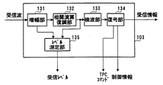
図2は、図1に示した移動局の受信部103の構成を示すブロック図である。
【0044】
受信部103は、受信波を増幅する増幅部131と、増幅後の受信波の周波数をベースバンドに変換して相関演算を行い希望波信号を復調する相関演算復調部132と、相関値を用いて検波処理を行い復号データを取り出す検波部133と、復号データに対してビタビ復号等の復号処理を行って受信情報、制御情報及びTPCコマンドを出力する復号部134と、増幅部131からの受信波レベルと相関演算復調部132からの希望波信号レベルとの比であるSIRを測定するレベル測定部135とを有する。
【0045】
図3は、図1に示した移動局の送信部104の構成を示すブロック図である。
【0046】
送信部104は、送信情報に制御情報を挿入して畳み込み符号等の符号化処理を行う符号化部151と、符号化データを一次変調及び拡散処理を行って無線周波数に周波数変換する変調部152と、送信電力制御部106からの送信電力値に基づいて変調された送信波を増幅する増幅部153とを有する。
【0047】
図4は、図1に示した移動局の送信電力制御部106の構成を示すブロック図である。
【0048】
OL−TPC(オープンループ送信電力制御)部161は、既知である通信相手の送信レベルから、レベル測定部135から出力された受信レベルを減算して無線区間においてロスしたレベルを算出し、このロスしたレベルに目標とする通信相手の受信レベルを加算して送信電力値を決定する。例えば、受信レベルが通信相手の送信レベルより25dB小さい場合に、目標とする通信相手の受信レベルに対して送信電力を25dB上げる。
【0049】
CL−TPC(クローズドループ送信電力制御)部162は、復号部134から出力されたTPCコマンドの内容に基いて前回の送信電力値を予め決められた変動量だけ増減して送信電力値を算出する。例えば、TPCコマンド「0」が増加命令であり、TPCコマンド「1」が低減命令であり、変動量が1dBである場合において、TPCコマンドが「0」のときに前回の送信電力に対して送信電力を1dB上げる。
【0050】
減算器163は、CL−TPC部162より出力された送信電力値からOL−TPC部161より出力された送信電力値を減算し、差分値を補正値算出部164にする。
【0051】
補正値算出部164は、減算器163から出力された差分値に基づいて、移動局の受信レベル測定誤差等を補正する補正値を算出して確定する。そして、補正値を確定したとき、その旨を示す制御情報をモード切替部165に出力する。また、モード切替部165から制御信号を入力した場合、確定した補正値を固定し、切替スイッチ167に出力する。
【0052】
補正値の確定方法として、差分値の平均値の変動幅が予め設定された閾値を下回ったとき、その時点での差分値の平均値を補正値として確定する方法、あるいは、補正値算出を開始してから一定時間経過したときの差分値の平均値を補正値として確定する方法等がある。
【0053】
なお、平均値の算出方法として、一定時間入力した差分値を単純に平均化する方法、あるいは、差分値に対して時間的な比重をつけて平均化する方法等がある。
【0054】
モード切替部165は、復号部134あるいは補正値算出部164からの制御情報に基づいて、切替スイッチ167及び切替スイッチ169を切換え制御する。また、モード切替部165は、所定のモードに移行するとき、補正値算出部164に対して制御信号を出力し、補正値を固定させる。なお、モード切替部165の動作の詳細については後述する。
【0055】
「0」データ出力部166は、補正値として「0」を出力する。切替スイッチ167は、モード切替部165の制御に基づいて、補正値算出部164あるいは「0」データ出力部166のいずれかから出力された補正値を加算器168に出力する。
【0056】
加算器168は、OL−TPC部161に対して切替スイッチ167からの補正値を加算する。
【0057】
切替スイッチ169は、モード切替部165の制御に基づいて、加算器168あるいはCL−TPC部162のいずれかから出力された送信電力値を増幅部153に出力する。
【0058】
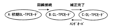
以下、モード切替部165の切替スイッチ167及び切替スイッチ169に対する切換え制御動作について、図5の状態遷移図、及び、図6の送信電力の推移を示す図を用いて説明する。
【0059】
まず、初期OL−TPCモード(A)として、電源を投入してから回線が確立するまでの期間、モード切替部165は、切替スイッチ167を「0」データ出力部166と接続させ、切替スイッチ169を加算器168と接続させる。この結果、移動局は、受信レベルに基づく送信電力値に対して補正を行わないオープンループ送信電力制御を行う。
【0060】
次に、モード切替部165は、復号部134から出力された制御情報から回線が確立された旨の情報を得たとき、切替スイッチ169をCL−TPC部162と接続させ、CL−TPCモード(B)に移行する。この結果、移動局は、受信波に載せられたTPCコマンドに基づく送信電力値でクローズドループ送信電力制御を行う。
【0061】
ここで、クローズドループ送信電力制御を行っている間、OL−TPC部161は継続して送信電力値を算出する。これは、仮にオープンループ送信電力制御を行っているとした場合の推定送信電力値である。また、上述したように、補正値算出部164は、CL−TPC部162から出力された現在使用されている送信電力値から推定送信電力値を減算した値に基づいて補正値を算出して確定し、補正値を確定した旨の制御情報をモード切替部165に出力する。
【0062】
モード切替部165は、補正値を確定した旨の制御情報を入力すると、切替スイッチ167を補正値算出部164に接続させ、切替スイッチ169を加算器168と接続させ、OL−TPCモード(C)に移行する。また、この時、補正値算出部164に対して制御信号を出力し、補正値を固定させる。この結果、移動局は、受信レベルに基づく送信電力値に対して受信レベル測定誤差等を補正した送信電力値を用いてオープンループ送信電力制御を行う。
【0063】
受信レベルに基づく送信電力値に対して受信レベル測定誤差等を補正することにより、クローズドループ送信電力制御を行った場合とほぼ同じ送信電力値とすることができ、しかも、高速なフェージングや強烈な干渉波の出現した場合にも対応できる。OL−TPCモード(C)に移行後、移動局はこの状態を維持する。
【0064】
ただし、ハンドオーバ時には、移動先セルの基地局における受信レベル誤差等を補正する必要があるため、図7に示すように、移動局は、CL−TPCモード(B)に移行し、クローズドループ送信電力制御を行う。モード切替部165は、復号部134から出力された制御情報からハンドオーバを開始する旨の情報を得たとき、切替スイッチ169をCL−TPC部162に接続させ、補正値算出部164に対して制御信号を出力し、補正値を再度計算させる。
【0065】
また、ハンドオーバ時以外にも、補正値の精度が低下した移動局が判断した場合に、OL−TPCモード(C)からCL−TPCモード(B)に移行させることができる。補正値の精度が低下したと判断できる場合として、移動局側でTPCコマンドを監視して、増加命令又は低減命令が一定回数続いた場合、あるいは、一定期間内において増加命令と低減命令の比率に極端な差がある場合がある。さらに、基地局が受信レベル、SIR、誤り検出符号等による通信品質から補正値の精度が低下したと判断し、判断結果を制御情報として移動局に送信してもよい。
【0066】
また、図8に示すように、受信レベルをいくつかの領域に区分けし、所定時間における平均受信レベルが区分けした領域を移動した場合にCL−TPCモード(B)に移行することもできる。これは、受信レベルによって誤差の出方の傾向が異なる場合に有効である。
【0067】
また、移動局は、予め補正値の有効期間を設定し、OL−TPCモード(C)に移行してから有効期間を経過した時点でCL−TPCモード(B)に移行することもできる。
【0068】
このように、クローズドループ送信電力制御を行っている間に受信レベル測定誤差等を補正する補正値を算出し、受信レベルに基づく送信電力値に補正値を加算した値によりオープンループ送信電力制御を行うことにより、受信測定精度を高めることなく受信レベル測定誤差を補正し、しかも、高速なフェージングや強烈な干渉波の出現した場合にも対応できる送信電力制御を行うことができる。
【0069】
しかも、オープンループ送信電力制御は、クローズドループ送信電力制御に比べてTPC誤差が少ないので、オープンループ送信電力制御を行っている時間が長い本発明において、システムのチャネル容量の増加を図ることができる。
【0070】
また、必要に応じて、オープンループ送信電力制御からクローズドループ送信電力制御に送信電力制御方法を適応的に切換えることができる。
【0071】
(実施の形態2)
実施の形態1では、移動局が、オープンループ送信電力制御とクローズドループ送信電力制御とを適応的に切換え形態について説明した。
【0072】
ここで、移動局がオープンループ送信電力制御を行っている間、基地局はTPCコマンドを送信する必要がない。よって、移動局がオープンループ送信電力制御を行っていることを基地局が検知して、TPCコマンドの代りに他の情報を送信すれば、下り回線における伝送効率が向上する。
【0073】
実施の形態2は、実施の形態1に係る送受信装置を備えた移動局がオープンループ送信電力制御を行っている間、基地局においてTPCコマンドを送信しない形態である。図9は、本実施の形態に係る基地局の構成を示すブロック図である。
【0074】
図9に示す基地局において、無線周波数の信号波を送受信するアンテナ201と、送信受信のタイミングを切換える送受信切替部202と、受信波の増幅量をユーザ毎に分配する増幅分配部203と、受信波を処理して受信情報、制御情報及び受信レベルを取り出す受信部204と、制御情報及び受信レベルに基づいて各部の制御を行う制御部205と、送信情報、制御情報及びTPCコマンドを載せた送信波を送信する送信部206と、各ユーザに対する送信波を多重して増幅する多重増幅部207とから主に構成される。また、制御部205は、受信レベルに基づいてTPCコマンドを生成するTPCコマンド生成部208を有する。
【0075】
図10は、図9に示した基地局の受信部204の構成を示すブロック図である。
【0076】
受信部204は、受信波の周波数をベースバンドに変換して相関演算を行い希望波信号を復調する相関演算復調部241と、相関値を用いて検波処理を行い復号データを取り出す検波部242と、復号データに対してビタビ復号等の復号処理を行って受信情報及び制御情報を出力する復号部243と、増幅分配部203からの増幅量と相関演算復調部132からの希望波信号レベルとの比であるSIRを測定するレベル測定部244とを有する。
【0077】
図11は、図9に示した基地局の送信部206の構成を示すブロック図である。
【0078】
送信部206は、送信情報に制御情報及びTPCコマンドを挿入して畳み込み符号等の符号化処理を行う符号化部261と、符号化データを一次変調及び拡散処理を行って無線周波数に周波数変換する変調部262と、変調された送信波を増幅する増幅部263とを有する。
【0079】
図12は、図9に示した基地局のTPCコマンド生成部208の構成を示すブロック図である。
【0080】
図12において、比較部181は、レベル測定部244から出力された受信レベルが基準値282より高いか低いかに基づき、移動局に送信電力の増加あるいは低減を命令するTPCコマンドを生成する。
【0081】
切替スイッチ283は、復号部243からの制御情報に基づき、TPCコマンドを挿入するべき送信スロットの位置に、比較部281から出力されたTPCコマンドあるいはその他の情報を挿入する。
【0082】
すなわち、現在、移動局が、クローズドループ送信電力制御を行っている場合にはTPCコマンドを挿入し、オープンループ送信電力制御を行っている場合には他の情報を挿入する。
【0083】
このように、通信相手がオープンループ送信電力制御を行っている間、TPCコマンドの代りに他の情報を送信することにより伝送効率が向上する。これは、特に、オープンループ送信電力制御を行っている時間が長い本発明において有効である。
【0084】
なお、上記の各実施の形態では、各モードの移動タイミングを移動局が独自に判断する場合について説明したが、本発明では、基地局が各モードの移行タイミングを判断し、制御情報により移動局に移行タイミングを指示することもできる。
【0085】
また、上記の各実施の形態では、移動局における上り回線の送信電力制御について説明したが、本発明は、基地局における下り回線の送信電力制御にも用いることができる。
【0086】
また、上記の各実施の形態では、送信情報と共に制御情報及びTPCコマンドも誤り訂正符号化処理して送信する場合を示しているが、本発明では、制御情報及びTPCコマンドを誤り訂正符号化処理しない場合でも同様の効果を得ることができる。この場合、制御情報及びTPCコマンドは検波部にて取り出される。
【0087】
【発明の効果】
以上説明したように、本発明の送受信装置によれば、適応的にクローズドループ送信電力制御とオープンループ送信電力制御とを切換えることにより両者の特性を活かし、受信測定精度を高めることなく受信レベル測定誤差を補正し、しかも、高速なフェージングや強烈な干渉波の出現した場合にも対応できる送信電力制御を行うことができる。
【図面の簡単な説明】
【図1】本発明の実施の形態1に係る送受信装置を備えた移動局の構成を示すブロック図
【図2】図1に示す移動局の受信部の構成を示すブロック図
【図3】図1に示す移動局の送信部の構成を示すブロック図
【図4】図1に示す移動局の送信電力制御部の構成を示すブロック図
【図5】上記実施の形態に係る移動局の状態遷移図
【図6】上記実施の形態に係る移動局の送信電力の推移を示す図
【図7】上記実施の形態に係る移動局のハンドオーバ時の状態遷移図
【図8】上記実施の形態に係る移動局の受信レベルの区分けに基づく状態遷移図
【図9】本発明の実施の形態2に係る基地局の構成を示すブロック図である。
【図10】図9に示す基地局の受信部の構成を示すブロック図
【図11】図9に示す基地局の送信部の構成を示すブロック図
【図12】図9に示す基地局のTPCコマンド生成部の構成を示すブロック図
【符号の説明】
106 送信電力制御部
153 増幅部
161 OL−TPC(オープンループ送信電力制御)部
162 CL−TPC(クローズドループ送信電力制御)部
164 補正値算出部
165 モード切替部
167、169、283 切替スイッチ
208 TPCコマンド生成部
281 比較部[0001]
BACKGROUND OF THE INVENTION
The present invention relates to a transmission / reception device that is mounted on a communication device of a mobile radio communication system and performs transmission power control.
[0002]
[Prior art]
CDMA (Code Division Multiple Access), which is one of access methods in wireless communication, is an access method in which users share the same frequency and the same time. Therefore, when the desired transmitting station is far away and the undesired interfering station is nearby, if each station transmits with the same power, the signal level from the interfering station is larger than the signal level of the desired transmitting station. Therefore, there is a problem that communication becomes impossible.
[0003]
In land mobile communications, fading is one of the causes that degrade the line quality. In a propagation path in land mobile communication, a standing wave is generated when a signal transmitted from a base station is reflected, scattered, or diffracted by buildings around the mobile station. When the mobile station moves in this area, the level of the signal from the base station drops in proportion to the moving speed, and fading that degrades the reception quality occurs.
[0004]
For this reason, in the cellular system using CDMA, the problem is solved by compensating for fading fluctuation and performing transmission power control (TPC) so that the reception levels are equal.
[0005]
Typical transmission power control includes closed loop transmission power control and open loop transmission power control.
[0006]
Closed loop transmission power control measures the SIR corresponding to the reception quality at the communication partner side for its own transmission signal, reduces the transmission power when the measured SIR value is higher than the target SIR value, and the measured SIR value is In this method, a control command (hereinafter referred to as “TPC command”) for increasing the transmission power when it is lower than the target SIR value is transmitted on the reverse line, and the transmission power is controlled based on the contents of the TPC command.
[0007]
On the other hand, open-loop transmission power control calculates the level lost in the radio section by subtracting the reception level from the transmission level of the known communication partner, and adds the target reception level of the communication partner to this lost level. This is a method for controlling the transmission power value.
[0008]
[Problems to be solved by the invention]
However, closed-loop transmission power control has a drawback in that it has a large control delay and is difficult to control dynamically, so that there is a risk that the communication quality of the system may be greatly reduced when fast fading or intense interference waves appear.
[0009]
In addition, since open loop transmission power control cannot cope with the case where the appropriate reception level for each base station differs, an offset error may occur in the reception level of the base station, and the reception level measurement error for each mobile station cannot be corrected. , It has the disadvantage that the reception measurement accuracy of the mobile station must be increased.
[0010]
That is, the closed loop transmission power control and the open loop transmission power control have advantages and disadvantages, respectively.
[0011]
The present invention has been made in view of the above points, and by switching between closed-loop transmission power control and open-loop transmission power control adaptively, the characteristics of both are utilized, and reception level measurement error is achieved without increasing reception measurement accuracy. It is another object of the present invention to provide a transmission / reception apparatus capable of correcting transmission power and performing transmission power control that can cope with the occurrence of high-speed fading and intense interference waves.
[0012]
[Means for Solving the Problems]
The gist of the present invention is to perform closed-loop transmission power control based on a transmission power value based on a TPC command after establishing a line, and at the same time, to set a correction value based on a difference between a transmission power value based on a reception level and a transmission power value based on a TPC command. After calculating and calculating the correction value, open loop transmission power control is performed using a value obtained by adding the correction value to the transmission power value based on the reception level.
[0013]
DETAILED DESCRIPTION OF THE INVENTION
The transmission / reception apparatus according to the first aspect of the present invention includes a first power value calculation unit that calculates a first power value based on a reception level, and a second power value that calculates a second power value based on a TPC command in the received signal. 2 power value calculation means, correction value calculation means for calculating a correction value based on the difference between the second power value and the first power value, and the transmission power value as the first power value and the second transmission value. And a power value selection means for selecting either a power value or a third power value obtained by adding the correction value to the first power value.
[0014]
In the transmission / reception apparatus according to the second aspect of the present invention, in the first aspect, the correction value calculation means averages a value obtained by subtracting the first power value from the second power value, and the fluctuation amount of the average value is preset. When the value falls below the threshold value, the average value is determined as the correction value.
[0015]
In the transmitter / receiver according to the third aspect of the present invention, in the second aspect, the correction value calculating means averages the value obtained by subtracting the first power value from the second power value with a temporal specific gravity. The structure to do is taken.
[0016]
In the transmitter / receiver according to the fourth aspect of the present invention, in any of the first to third aspects, the power value selecting means selects the first power value as the transmission power value until the line is established, A configuration is adopted in which the second power value is selected as the transmission power value from the establishment until the correction value is determined, and the third power value is selected as the transmission power value after the correction value is determined.
[0017]
With these configurations, it is possible to correct the reception level measurement error without increasing the reception measurement accuracy, and to perform transmission power control that can cope with a case where high-speed fading or intense interference waves appear.
[0018]
Moreover, since the open loop transmission power control has a smaller TPC error than the closed loop transmission power control, the channel capacity of the system can be increased in the present invention in which the open loop transmission power control is performed for a long time. .
[0019]
In any one of the first to fourth aspects, the transmission / reception apparatus according to the fifth aspect of the present invention employs a configuration in which the power value selection means selects the second power value as the transmission power value at the time of handover.
[0020]
In the transmitter / receiver according to a sixth aspect of the present invention, in any one of the first to fifth aspects, the power value selection means selects the second power value as the transmission power value when the accuracy of the correction value decreases. The structure to do is taken.
[0021]
In the transmitter / receiver according to a seventh aspect of the present invention, in any one of the first to sixth aspects, the power value selection unit divides the reception level into several areas, and the average reception level in a predetermined time is divided. When the area is moved, the second power value is selected as the transmission power value.
[0022]
In the transmitter / receiver according to the eighth aspect of the present invention, in any one of the first to seventh aspects, the power value selection unit sets the effective period of the correction value in advance and determines the effective value after determining the correction value. The configuration is adopted in which the second power value is selected as the transmission power value when elapses.
[0023]
In the transmitter / receiver according to the ninth aspect of the present invention, in any of the fifth to eighth aspects, the correction value calculating means corrects when the power value selecting means selects the second power value as the transmission power value. A configuration for calculating the value again is adopted.
[0024]
With these configurations, the transmission power control method can be adaptively switched from open-loop transmission power control to closed-loop transmission power control as necessary.
[0025]
The communication terminal apparatus according to the tenth aspect of the present invention employs a configuration in which the transmission / reception apparatus according to any one of the first to ninth aspects is mounted.
[0026]
The base station apparatus according to the eleventh aspect of the present invention employs a configuration for performing wireless communication with the communication terminal apparatus according to the tenth aspect.
[0027]
A base station apparatus according to a twelfth aspect of the present invention employs a configuration in the eleventh aspect that stops transmission of a TPC command when the communication terminal apparatus performs transmission power control based on the reception level.
[0028]
A base station apparatus according to a thirteenth aspect of the present invention employs a configuration in which the transmission / reception apparatus according to any one of the first to ninth aspects is mounted.
[0029]
The communication terminal apparatus according to the fourteenth aspect of the present invention employs a configuration for performing wireless communication with the base station apparatus according to the thirteenth aspect.
[0030]
In a fourteenth aspect, a communication terminal according to a fifteenth aspect of the present invention employs a configuration in which transmission of a TPC command is stopped when a base station apparatus performs transmission power control based on a reception level.
[0031]
With these configurations, it is possible to correct the reception level measurement error without increasing the reception measurement accuracy, and to achieve wireless communication that performs transmission power control that can cope with the occurrence of high-speed fading and intense interference waves. it can.
[0032]
Furthermore, while the communication partner is performing open loop transmission power control, transmission efficiency is improved by transmitting other information instead of the TPC command. This is particularly effective in the present invention in which the open loop transmission power control is performed for a long time.
[0033]
In the transmission power control method according to the sixteenth aspect of the present invention, the transmission power is controlled by the first transmission power value calculated based on the reception level until the line is established. The transmission power is controlled based on the second transmission power value calculated based on the TPC command, the correction value is calculated from the difference between the second transmission power value and the first transmission power value, and the correction value is determined. Then, a method is adopted in which transmission power is controlled by a third transmission power value obtained by adding the correction value to the first transmission power value.
[0034]
The transmission power control method according to the seventeenth aspect of the present invention employs, in the sixteenth aspect, a method in which the transmission power is controlled by the second transmission power value at the time of handover and the correction value is calculated again.
[0035]
The transmission power control method according to the eighteenth aspect of the present invention controls the transmission power according to the second transmission power value when it is determined in any of the sixteenth and seventeenth aspects that the accuracy of the correction value has decreased. Then, a method of calculating the correction value again is adopted.
[0036]
The transmission power control method according to the nineteenth aspect of the present invention is the transmission power control method according to any of the sixteenth to eighteenth aspects, wherein the reception level is divided into several areas, and the area where the average reception level in a predetermined time is divided is moved. In this case, a method is employed in which the transmission power is controlled by the second transmission power value and the correction value is calculated again.
[0037]
The transmission power control method according to the twentieth aspect of the present invention is the transmission power control method according to any of the sixteenth to nineteenth aspects, wherein the effective period of the correction value is set in advance and the effective period has elapsed after the correction value is determined. Then, a method is employed in which the transmission power is controlled by the second transmission power value and the correction value is calculated again.
[0038]
By these methods, it is possible to correct the reception level measurement error without increasing the reception measurement accuracy, and to perform transmission power control that can cope with the case where high-speed fading or intense interference waves appear.
[0039]
Furthermore, the transmission power control method can be adaptively switched from open loop transmission power control to closed loop transmission power control as necessary.
[0040]
Hereinafter, embodiments of the present invention will be described in detail with reference to the accompanying drawings.
[0041]
(Embodiment 1)
FIG. 1 is a block diagram showing a configuration of a mobile station provided with a transmission / reception apparatus according to Embodiment 1 of the present invention.
[0042]
In the mobile station shown in FIG. 1, an
[0043]
FIG. 2 is a block diagram showing a configuration of receiving
[0044]
The receiving
[0045]
FIG. 3 is a block diagram showing a configuration of transmitting
[0046]
The
[0047]
FIG. 4 is a block diagram showing a configuration of transmission
[0048]
The OL-TPC (open loop transmission power control)
[0049]
A CL-TPC (closed loop transmission power control)
[0050]
The
[0051]
Based on the difference value output from the
[0052]
As a method for determining the correction value, when the fluctuation range of the average value of the difference value falls below a preset threshold, the average value of the difference value at that time is determined as the correction value, or correction value calculation is started Then, there is a method of determining the average value of the difference values when a certain time has passed as a correction value.
[0053]
As an average value calculation method, there are a method of simply averaging the difference values input for a certain period of time, a method of averaging the difference values with a temporal specific gravity, and the like.
[0054]
The
[0055]
The “0”
[0056]
The
[0057]
The
[0058]
Hereinafter, the switching control operation for the
[0059]
First, as the initial OL-TPC mode (A), the
[0060]
Next, when the
[0061]
Here, while performing the closed loop transmission power control, the OL-
[0062]
When the control information indicating that the correction value has been determined is input, the
[0063]
By correcting the reception level measurement error etc. with respect to the transmission power value based on the reception level, it is possible to make the transmission power value almost the same as when closed-loop transmission power control is performed, and in addition, fast fading and intense It is also possible to cope with the appearance of interference waves. After shifting to the OL-TPC mode (C), the mobile station maintains this state.
[0064]
However, since it is necessary to correct a reception level error or the like in the base station of the movement destination cell at the time of handover, the mobile station shifts to the CL-TPC mode (B) as shown in FIG. Take control. When the
[0065]
In addition to the handover, when a mobile station having a reduced correction value accuracy is determined, the OL-TPC mode (C) can be shifted to the CL-TPC mode (B). When it can be determined that the accuracy of the correction value has decreased, the TPC command is monitored on the mobile station side, and when the increase command or the decrease command continues for a certain number of times, or the ratio between the increase command and the decrease command within a certain period. There may be extreme differences. Furthermore, the base station may determine that the accuracy of the correction value has decreased from the communication quality based on the reception level, SIR, error detection code, etc., and transmit the determination result to the mobile station as control information.
[0066]
In addition, as shown in FIG. 8, the reception level can be divided into several areas, and the CL-TPC mode (B) can be shifted when the area where the average reception level in a predetermined time is moved. This is effective when the tendency of error occurrence differs depending on the reception level.
[0067]
Also, the mobile station can set the valid period of the correction value in advance, and can shift to the CL-TPC mode (B) when the valid period elapses after shifting to the OL-TPC mode (C).
[0068]
In this way, a correction value for correcting a reception level measurement error or the like is calculated during closed-loop transmission power control, and open-loop transmission power control is performed using a value obtained by adding the correction value to the transmission power value based on the reception level. By doing so, it is possible to correct the reception level measurement error without increasing the reception measurement accuracy, and to perform transmission power control that can cope with the occurrence of high-speed fading and intense interference waves.
[0069]
Moreover, since the open loop transmission power control has a smaller TPC error than the closed loop transmission power control, the channel capacity of the system can be increased in the present invention in which the open loop transmission power control is performed for a long time. .
[0070]
Further, the transmission power control method can be adaptively switched from open loop transmission power control to closed loop transmission power control as necessary.
[0071]
(Embodiment 2)
In the first embodiment, the mobile station adaptively switches between open loop transmission power control and closed loop transmission power control.
[0072]
Here, the base station does not need to transmit a TPC command while the mobile station is performing open loop transmission power control. Therefore, if the base station detects that the mobile station is performing open loop transmission power control and transmits other information instead of the TPC command, transmission efficiency in the downlink is improved.
[0073]
Embodiment 2 is a form in which a TPC command is not transmitted in a base station while a mobile station equipped with the transmission / reception apparatus according to Embodiment 1 is performing open loop transmission power control. FIG. 9 is a block diagram showing the configuration of the base station according to the present embodiment.
[0074]
In the base station shown in FIG. 9, an
[0075]
FIG. 10 is a block diagram showing a configuration of receiving
[0076]
The receiving
[0077]
FIG. 11 is a block diagram showing a configuration of transmitting
[0078]
The
[0079]
FIG. 12 is a block diagram showing a configuration of TPC
[0080]
In FIG. 12, the comparison unit 181 generates a TPC command that instructs the mobile station to increase or decrease the transmission power based on whether the reception level output from the
[0081]
Based on the control information from the
[0082]
That is, when the mobile station is currently performing closed loop transmission power control, a TPC command is inserted, and when the mobile station is performing open loop transmission power control, other information is inserted.
[0083]
In this way, while the communication partner is performing open-loop transmission power control, transmission efficiency is improved by transmitting other information instead of the TPC command. This is particularly effective in the present invention in which the open loop transmission power control is performed for a long time.
[0084]
In each of the above embodiments, the case where the mobile station independently determines the movement timing of each mode has been described. However, in the present invention, the base station determines the transition timing of each mode and uses the control information to determine the mobile station. It is also possible to instruct the transition timing.
[0085]
In each of the above embodiments, uplink transmission power control in the mobile station has been described. However, the present invention can also be used for downlink transmission power control in the base station.
[0086]
In each of the above-described embodiments, the control information and the TPC command are transmitted together with the transmission information after performing the error correction coding process. However, in the present invention, the control information and the TPC command are transmitted with the error correction coding process. Even if not, the same effect can be obtained. In this case, the control information and the TPC command are taken out by the detection unit.
[0087]
【The invention's effect】
As described above, according to the transmission / reception apparatus of the present invention, the reception level measurement can be performed without increasing the reception measurement accuracy by utilizing both characteristics by adaptively switching between the closed-loop transmission power control and the open-loop transmission power control. It is possible to perform transmission power control that corrects the error and can cope with a case where high-speed fading or intense interference appears.
[Brief description of the drawings]
FIG. 1 is a block diagram showing a configuration of a mobile station provided with a transmission / reception apparatus according to Embodiment 1 of the present invention.
2 is a block diagram showing a configuration of a receiving unit of the mobile station shown in FIG.
3 is a block diagram showing a configuration of a transmission unit of the mobile station shown in FIG.
4 is a block diagram showing a configuration of a transmission power control unit of the mobile station shown in FIG.
FIG. 5 is a state transition diagram of the mobile station according to the above embodiment.
FIG. 6 is a diagram showing transition of transmission power of the mobile station according to the embodiment.
FIG. 7 is a state transition diagram at the time of handover of the mobile station according to the embodiment.
FIG. 8 is a state transition diagram based on the reception level classification of the mobile station according to the embodiment.
FIG. 9 is a block diagram showing a configuration of a base station according to Embodiment 2 of the present invention.
10 is a block diagram showing a configuration of a receiving unit of the base station shown in FIG. 9;
11 is a block diagram showing a configuration of a transmission unit of the base station shown in FIG.
12 is a block diagram showing a configuration of a TPC command generation unit of the base station shown in FIG. 9;
[Explanation of symbols]
106 Transmission power control unit
153 Amplifier
161 OL-TPC (open loop transmission power control) unit
162 CL-TPC (Closed Loop Transmission Power Control) Unit
164 Correction value calculation unit
165 Mode switching part
167, 169, 283 selector switch
208 TPC command generator
281 comparison unit
Claims (20)
Priority Applications (9)
| Application Number | Priority Date | Filing Date | Title |
|---|---|---|---|
| JP10304499A JP3968190B2 (en) | 1999-03-06 | 1999-03-06 | Transceiver |
| US09/674,293 US6697634B1 (en) | 1999-03-06 | 2000-03-06 | Apparatus and method for selecting a transmit power value from multiple calculated power levels |
| EP00906710A EP1077531B1 (en) | 1999-03-06 | 2000-03-06 | Transmitting/receiving device and transmitting/receiving method |
| KR10-2000-7012340A KR100378970B1 (en) | 1999-03-06 | 2000-03-06 | Transmitting/receiving device and transmitting/receiving method |
| CA002330444A CA2330444C (en) | 1999-03-06 | 2000-03-06 | Apparatus and method for transmission/reception |
| AU28294/00A AU2829400A (en) | 1999-03-06 | 2000-03-06 | Transmitting/receiving device and transmitting/receiving method |
| CN00800243A CN1118943C (en) | 1999-03-06 | 2000-03-06 | Transmitting/receiving device and transmitting/receiving method |
| PCT/JP2000/001327 WO2000054417A1 (en) | 1999-03-06 | 2000-03-06 | Transmitting/receiving device and transmitting/receiving method |
| DE2000632071 DE60032071T2 (en) | 1999-03-06 | 2000-03-06 | METHOD AND DEVICE FOR SENDING RECEIPT |
Applications Claiming Priority (1)
| Application Number | Priority Date | Filing Date | Title |
|---|---|---|---|
| JP10304499A JP3968190B2 (en) | 1999-03-06 | 1999-03-06 | Transceiver |
Publications (2)
| Publication Number | Publication Date |
|---|---|
| JP2000261374A JP2000261374A (en) | 2000-09-22 |
| JP3968190B2 true JP3968190B2 (en) | 2007-08-29 |
Family
ID=14343678
Family Applications (1)
| Application Number | Title | Priority Date | Filing Date |
|---|---|---|---|
| JP10304499A Expired - Fee Related JP3968190B2 (en) | 1999-03-06 | 1999-03-06 | Transceiver |
Country Status (9)
| Country | Link |
|---|---|
| US (1) | US6697634B1 (en) |
| EP (1) | EP1077531B1 (en) |
| JP (1) | JP3968190B2 (en) |
| KR (1) | KR100378970B1 (en) |
| CN (1) | CN1118943C (en) |
| AU (1) | AU2829400A (en) |
| CA (1) | CA2330444C (en) |
| DE (1) | DE60032071T2 (en) |
| WO (1) | WO2000054417A1 (en) |
Families Citing this family (48)
| Publication number | Priority date | Publication date | Assignee | Title |
|---|---|---|---|---|
| GB0107746D0 (en) | 2001-03-28 | 2001-05-16 | Nokia Networks Oy | Transmissions in a communication system |
| JP2002185398A (en) * | 2000-12-18 | 2002-06-28 | Sony Corp | Method and system for controlling transmission power |
| KR100353641B1 (en) * | 2000-12-21 | 2002-09-28 | 삼성전자 주식회사 | Base station transmit antenna diversity apparatus and method in cdma communication system |
| JP2002271265A (en) * | 2001-03-07 | 2002-09-20 | Hitachi Kokusai Electric Inc | Radio station device |
| US9100457B2 (en) | 2001-03-28 | 2015-08-04 | Qualcomm Incorporated | Method and apparatus for transmission framing in a wireless communication system |
| US8077679B2 (en) | 2001-03-28 | 2011-12-13 | Qualcomm Incorporated | Method and apparatus for providing protocol options in a wireless communication system |
| US8121296B2 (en) | 2001-03-28 | 2012-02-21 | Qualcomm Incorporated | Method and apparatus for security in a data processing system |
| JP4592994B2 (en) * | 2001-03-29 | 2010-12-08 | Necエンジニアリング株式会社 | Transmission power control system and method, and base station used therefor |
| EP1411650B1 (en) | 2001-07-24 | 2014-11-26 | NTT DoCoMo, Inc. | Transmission power control apparatus and method in a mobile communication system |
| US7330446B2 (en) * | 2001-09-21 | 2008-02-12 | Industrial Technology Research Institute | Closed-loop power control method for a code-division multiple-access cellular system |
| US7352868B2 (en) | 2001-10-09 | 2008-04-01 | Philip Hawkes | Method and apparatus for security in a data processing system |
| US7649829B2 (en) | 2001-10-12 | 2010-01-19 | Qualcomm Incorporated | Method and system for reduction of decoding complexity in a communication system |
| US20030087607A1 (en) * | 2001-11-05 | 2003-05-08 | General Motors Corporation | Method for wireless modem carrier level control |
| US7010321B2 (en) * | 2002-02-04 | 2006-03-07 | Qualcomm Inc. | Power control avoiding outer loop wind-up |
| US6985751B2 (en) * | 2002-03-07 | 2006-01-10 | Siemens Communications, Inc. | Combined open and closed loop power control with differential measurement |
| US7088999B2 (en) * | 2002-08-20 | 2006-08-08 | Via Technologies, Inc. | Personal communication device with transmitted RF power strength indicator |
| WO2004049588A1 (en) | 2002-11-26 | 2004-06-10 | Interdigital Technology Corporation | Bias error compensated initial transmission power control for data services |
| US7599655B2 (en) | 2003-01-02 | 2009-10-06 | Qualcomm Incorporated | Method and apparatus for broadcast services in a communication system |
| CN1198419C (en) * | 2003-01-16 | 2005-04-20 | 大唐移动通信设备有限公司 | Control method based on power of down doing guidance time slot |
| JP2005005762A (en) * | 2003-06-09 | 2005-01-06 | Fujitsu Ltd | Transmission power control method and apparatus |
| US8098818B2 (en) | 2003-07-07 | 2012-01-17 | Qualcomm Incorporated | Secure registration for a multicast-broadcast-multimedia system (MBMS) |
| US8718279B2 (en) | 2003-07-08 | 2014-05-06 | Qualcomm Incorporated | Apparatus and method for a secure broadcast system |
| US8724803B2 (en) | 2003-09-02 | 2014-05-13 | Qualcomm Incorporated | Method and apparatus for providing authenticated challenges for broadcast-multicast communications in a communication system |
| US7493133B2 (en) | 2004-02-05 | 2009-02-17 | Qualcomm, Incorporated | Power control in ad-hoc wireless networks |
| CN100421357C (en) * | 2004-04-07 | 2008-09-24 | 明基电通股份有限公司 | System and method for correcting transmitter-receiver set |
| US7197692B2 (en) | 2004-06-18 | 2007-03-27 | Qualcomm Incorporated | Robust erasure detection and erasure-rate-based closed loop power control |
| US7594151B2 (en) * | 2004-06-18 | 2009-09-22 | Qualcomm, Incorporated | Reverse link power control in an orthogonal system |
| US8452316B2 (en) * | 2004-06-18 | 2013-05-28 | Qualcomm Incorporated | Power control for a wireless communication system utilizing orthogonal multiplexing |
| KR100725773B1 (en) * | 2004-08-20 | 2007-06-08 | 삼성전자주식회사 | Apparatus and method for adaptively changing the uplink power control scheme depending on the status of mobile station in a wireless mobile communication system using time division duplexing scheme |
| US7205842B2 (en) * | 2005-01-13 | 2007-04-17 | Telefonaktiebolaget Lm Ericsson (Publ) | Continuous alternating closed-open loop power control |
| US8848574B2 (en) | 2005-03-15 | 2014-09-30 | Qualcomm Incorporated | Interference control in a wireless communication system |
| US8942639B2 (en) | 2005-03-15 | 2015-01-27 | Qualcomm Incorporated | Interference control in a wireless communication system |
| JP4687171B2 (en) * | 2005-03-17 | 2011-05-25 | 株式会社日立製作所 | Wireless communication system, wireless communication apparatus, and transmission power control method in wireless communication system |
| US20060223446A1 (en) * | 2005-03-29 | 2006-10-05 | Francis Dominique | Methods of detecting mobile stations not following power control commands |
| KR101097021B1 (en) * | 2005-10-27 | 2011-12-20 | 콸콤 인코포레이티드 | Method and apparatus for estimating reverse link loading in a wireless communication system |
| US8315226B2 (en) | 2006-01-05 | 2012-11-20 | Qualcomm Incorporated | Power control and handoff with power control commands and erasure indications |
| KR100869922B1 (en) * | 2006-05-12 | 2008-11-21 | 삼성전자주식회사 | Apparatus and method for controlling uplink power in broadband wireless communication terminal |
| JP2008011285A (en) * | 2006-06-30 | 2008-01-17 | Fujitsu Ltd | Transmission power controller and transmission power control method |
| US8670777B2 (en) * | 2006-09-08 | 2014-03-11 | Qualcomm Incorporated | Method and apparatus for fast other sector interference (OSI) adjustment |
| US8442572B2 (en) | 2006-09-08 | 2013-05-14 | Qualcomm Incorporated | Method and apparatus for adjustments for delta-based power control in wireless communication systems |
| US8886245B2 (en) * | 2007-03-09 | 2014-11-11 | Qualcomm Incorporated | Messaging scheme for controlling uplink transmit power of a wireless device |
| US8744510B2 (en) * | 2007-03-13 | 2014-06-03 | Pranav Dayal | Power control method and apparatus for wireless communications |
| KR20100048844A (en) * | 2008-10-31 | 2010-05-11 | 삼성전자주식회사 | Apparatus and method for uplink power control in wireless communiation system |
| US8160634B1 (en) * | 2009-03-17 | 2012-04-17 | Sprint Spectrum L.P. | Intelligent power control in a wireless network |
| US9319990B2 (en) | 2011-10-03 | 2016-04-19 | Qualcomm Incorporated | Method and apparatus for uplink transmission power control and timing in coordinated multipoint transmission schemes |
| DE102015110160B4 (en) * | 2015-06-24 | 2018-03-29 | Intel IP Corporation | A multicast data transmission system and method of operating the same |
| US11082951B2 (en) | 2018-09-28 | 2021-08-03 | At&T Intellectual Property I, L.P. | Dynamically controlled UE output as a function of duty cycle and proximity sensor information |
| KR20230032083A (en) * | 2021-08-30 | 2023-03-07 | 삼성전자주식회사 | Electronic device and method for controlling setting of antenna in the electronic device comprising a plurality of antennas |
Family Cites Families (25)
| Publication number | Priority date | Publication date | Assignee | Title |
|---|---|---|---|---|
| US5056109A (en) * | 1989-11-07 | 1991-10-08 | Qualcomm, Inc. | Method and apparatus for controlling transmission power in a cdma cellular mobile telephone system |
| NZ255617A (en) * | 1992-09-04 | 1996-11-26 | Ericsson Telefon Ab L M | Tdma digital radio: measuring path loss and setting transmission power accordingly |
| JP2904335B2 (en) * | 1994-04-27 | 1999-06-14 | エヌ・ティ・ティ移動通信網株式会社 | Transmission power control method and mobile station device |
| JP2980156B2 (en) | 1994-05-12 | 1999-11-22 | エヌ・ティ・ティ移動通信網株式会社 | Transmission power control method and spread spectrum communication apparatus using the control method |
| JP2993554B2 (en) * | 1994-05-12 | 1999-12-20 | エヌ・ティ・ティ移動通信網株式会社 | Transmission power control method and communication device using the transmission power control method |
| JP2974274B2 (en) | 1994-05-12 | 1999-11-10 | エヌ・ティ・ティ移動通信網株式会社 | Transmission power control method and transmission power control device |
| JP3154462B2 (en) * | 1994-08-29 | 2001-04-09 | 日本電信電話株式会社 | Mobile communication system and mobile station device |
| WO1997008847A1 (en) * | 1995-08-31 | 1997-03-06 | Nokia Telecommunications Oy | Method and device for controlling transmission power of a radio transmitter in a cellular communication system |
| JP2773721B2 (en) * | 1995-12-28 | 1998-07-09 | 日本電気株式会社 | Transmission power control method |
| EP0807989B1 (en) * | 1996-05-17 | 2001-06-27 | Motorola Ltd | Devices for transmitter path weights and methods therefor |
| FI103555B1 (en) * | 1996-06-17 | 1999-07-15 | Nokia Mobile Phones Ltd | Transmission power control in wireless packet data transmission |
| KR980007105A (en) * | 1996-06-28 | 1998-03-30 | 김광호 | Method for controlling transmission power of mobile station |
| JP3818702B2 (en) * | 1996-08-07 | 2006-09-06 | 松下電器産業株式会社 | CDMA radio transmission system, transmission power control apparatus and transmission power control measuring apparatus used in the system |
| JPH1065609A (en) * | 1996-08-23 | 1998-03-06 | Sony Corp | Communication method, base station and terminal equipment |
| JPH10117166A (en) * | 1996-10-08 | 1998-05-06 | Nec Ic Microcomput Syst Ltd | Mobile body communication system |
| JP2923867B2 (en) * | 1996-10-28 | 1999-07-26 | 日本電気株式会社 | Transmission power control method |
| JP3586348B2 (en) | 1997-03-05 | 2004-11-10 | 富士通株式会社 | Signal to interference power ratio measurement apparatus, signal to interference power ratio measurement method, and transmission power control method under CDMA communication system |
| US6236863B1 (en) * | 1997-03-31 | 2001-05-22 | Oki Telecom, Inc. | Comprehensive transmitter power control system for radio telephones |
| US6072784A (en) * | 1997-07-25 | 2000-06-06 | At&T Corp. | CDMA mobile station wireless transmission power management with adaptive scheduling priorities based on battery power level |
| JP3397677B2 (en) * | 1998-02-10 | 2003-04-21 | 松下電器産業株式会社 | Transmission power control device and wireless communication device |
| KR100260820B1 (en) * | 1998-03-24 | 2000-07-01 | 조정남 | Power control apparatus and its method |
| JP2000022611A (en) * | 1998-06-29 | 2000-01-21 | Matsushita Electric Ind Co Ltd | Transmission power control method and radio communication equipment |
| CN1128515C (en) * | 1998-07-13 | 2003-11-19 | 三星电子株式会社 | Power control device and method for reverse link common channel in mobile communication system |
| JP2000151317A (en) * | 1998-11-10 | 2000-05-30 | Hitachi Ltd | Transmitter and power amplifier |
| US6445930B1 (en) * | 1999-04-21 | 2002-09-03 | Joseph Peter Bartelme | Power control system and method for use with wireless communications system |
-
1999
- 1999-03-06 JP JP10304499A patent/JP3968190B2/en not_active Expired - Fee Related
-
2000
- 2000-03-06 KR KR10-2000-7012340A patent/KR100378970B1/en not_active IP Right Cessation
- 2000-03-06 AU AU28294/00A patent/AU2829400A/en not_active Abandoned
- 2000-03-06 DE DE2000632071 patent/DE60032071T2/en not_active Expired - Lifetime
- 2000-03-06 CA CA002330444A patent/CA2330444C/en not_active Expired - Fee Related
- 2000-03-06 WO PCT/JP2000/001327 patent/WO2000054417A1/en active IP Right Grant
- 2000-03-06 US US09/674,293 patent/US6697634B1/en not_active Expired - Lifetime
- 2000-03-06 CN CN00800243A patent/CN1118943C/en not_active Expired - Fee Related
- 2000-03-06 EP EP00906710A patent/EP1077531B1/en not_active Expired - Lifetime
Also Published As
| Publication number | Publication date |
|---|---|
| EP1077531A4 (en) | 2005-05-11 |
| CN1118943C (en) | 2003-08-20 |
| JP2000261374A (en) | 2000-09-22 |
| CA2330444C (en) | 2005-01-04 |
| EP1077531B1 (en) | 2006-11-29 |
| WO2000054417A1 (en) | 2000-09-14 |
| CA2330444A1 (en) | 2000-09-14 |
| CN1302479A (en) | 2001-07-04 |
| KR100378970B1 (en) | 2003-04-07 |
| US6697634B1 (en) | 2004-02-24 |
| DE60032071T2 (en) | 2007-04-12 |
| DE60032071D1 (en) | 2007-01-11 |
| KR20010043342A (en) | 2001-05-25 |
| EP1077531A1 (en) | 2001-02-21 |
| AU2829400A (en) | 2000-09-28 |
Similar Documents
| Publication | Publication Date | Title |
|---|---|---|
| JP3968190B2 (en) | Transceiver | |
| US6377813B1 (en) | Forward link closed loop power control for a third generation wideband CDMA system | |
| JP3551937B2 (en) | Communication control method in mobile communication system and base station used therefor | |
| JP3543959B2 (en) | base station | |
| US6487394B1 (en) | Radio communication device and method of controlling transmission rate | |
| US6526028B1 (en) | CDMA mobile communication system with consideration of fading | |
| KR100874101B1 (en) | Method and apparatus for controlling transmission power while in soft handoff | |
| JP3397677B2 (en) | Transmission power control device and wireless communication device | |
| US6912405B2 (en) | Mobile station apparatus and transmission power control method | |
| JP4921561B2 (en) | Reduction of current consumption using RX diversity circuit | |
| EP1128577A1 (en) | Radio communication device and radio communication method | |
| EP1215926A1 (en) | Transmission power controller | |
| US7613432B2 (en) | Method of controlling mobile communication system, control device, and mobile communication system | |
| KR20010113744A (en) | Adaptive power control in a radio communications system | |
| EP1139685B1 (en) | Wireless communication device and transmission power control method | |
| US20070218934A1 (en) | Communication Terminal and Transmission Power Control Method | |
| US6968212B1 (en) | Base station apparatus that directively transmits a modulated packet signal to a priority destination and packet transmission method thereto | |
| JP2002051375A (en) | Base station equipment and packet transmission method | |
| JPH11186940A (en) | Reception method, reception quality estimation method, transmission power control method and transmitter-receiver in cdma system | |
| Gunaratne et al. | Performance of SIR-based power control for UMTS | |
| KR20010066567A (en) | Forward power control device for digital communication system |
Legal Events
| Date | Code | Title | Description |
|---|---|---|---|
| A621 | Written request for application examination |
Free format text: JAPANESE INTERMEDIATE CODE: A621 Effective date: 20060303 |
|
| TRDD | Decision of grant or rejection written | ||
| A01 | Written decision to grant a patent or to grant a registration (utility model) |
Free format text: JAPANESE INTERMEDIATE CODE: A01 Effective date: 20070529 |
|
| A61 | First payment of annual fees (during grant procedure) |
Free format text: JAPANESE INTERMEDIATE CODE: A61 Effective date: 20070604 |
|
| R150 | Certificate of patent or registration of utility model |
Free format text: JAPANESE INTERMEDIATE CODE: R150 |
|
| FPAY | Renewal fee payment (event date is renewal date of database) |
Free format text: PAYMENT UNTIL: 20100608 Year of fee payment: 3 |
|
| FPAY | Renewal fee payment (event date is renewal date of database) |
Free format text: PAYMENT UNTIL: 20110608 Year of fee payment: 4 |
|
| FPAY | Renewal fee payment (event date is renewal date of database) |
Free format text: PAYMENT UNTIL: 20120608 Year of fee payment: 5 |
|
| FPAY | Renewal fee payment (event date is renewal date of database) |
Free format text: PAYMENT UNTIL: 20120608 Year of fee payment: 5 |
|
| FPAY | Renewal fee payment (event date is renewal date of database) |
Free format text: PAYMENT UNTIL: 20130608 Year of fee payment: 6 |
|
| S533 | Written request for registration of change of name |
Free format text: JAPANESE INTERMEDIATE CODE: R313533 |
|
| R350 | Written notification of registration of transfer |
Free format text: JAPANESE INTERMEDIATE CODE: R350 |
|
| R250 | Receipt of annual fees |
Free format text: JAPANESE INTERMEDIATE CODE: R250 |
|
| R250 | Receipt of annual fees |
Free format text: JAPANESE INTERMEDIATE CODE: R250 |
|
| S111 | Request for change of ownership or part of ownership |
Free format text: JAPANESE INTERMEDIATE CODE: R313113 |
|
| R360 | Written notification for declining of transfer of rights |
Free format text: JAPANESE INTERMEDIATE CODE: R360 |
|
| R360 | Written notification for declining of transfer of rights |
Free format text: JAPANESE INTERMEDIATE CODE: R360 |
|
| R371 | Transfer withdrawn |
Free format text: JAPANESE INTERMEDIATE CODE: R371 |
|
| S111 | Request for change of ownership or part of ownership |
Free format text: JAPANESE INTERMEDIATE CODE: R313113 |
|
| R350 | Written notification of registration of transfer |
Free format text: JAPANESE INTERMEDIATE CODE: R350 |
|
| R250 | Receipt of annual fees |
Free format text: JAPANESE INTERMEDIATE CODE: R250 |
|
| LAPS | Cancellation because of no payment of annual fees |