RU2385373C1 - Production assembly line of track switches - Google Patents
Production assembly line of track switches Download PDFInfo
- Publication number
- RU2385373C1 RU2385373C1 RU2008146340/11A RU2008146340A RU2385373C1 RU 2385373 C1 RU2385373 C1 RU 2385373C1 RU 2008146340/11 A RU2008146340/11 A RU 2008146340/11A RU 2008146340 A RU2008146340 A RU 2008146340A RU 2385373 C1 RU2385373 C1 RU 2385373C1
- Authority
- RU
- Russia
- Prior art keywords
- bars
- track
- line
- rails
- trolleys
- Prior art date
Links
Images

Landscapes
- Warehouses Or Storage Devices (AREA)
Abstract
Description
Изобретение относится к области механизации путевого хозяйства железнодорожного транспорта и может быть использовано при сборке стрелочных переводов железнодорожного пути на производственных базах.The invention relates to the field of mechanization of track facilities of railway transport and can be used in the assembly of railroad switches on production bases.
Известен стенд для сборки стрелочных переводов (журнал «Путь и путевое хозяйство», 2005 г., №8), на котором с помощью шаблонной линейки с нанесенными отметками оси бруса, боковых и торцевых упоров раскладывают брусья и рельсы краном. К недостаткам, при применении известного стенда, следует отнести необходимость применения ручного труда при точной раскладке брусьев и последовательное выполнение всех операций по сборке стрелочного перевода на одном месте, что снижает производительность.There is a well-known stand for assembling turnouts (the magazine “Way and Track Management”, 2005, No. 8), on which the bars and rails are laid out using a gauge line with the marked axis of the beam, side and end stops. The disadvantages when using a well-known stand, include the need for manual labor with the exact layout of the beams and the consistent execution of all the operations of assembling the turnout in one place, which reduces productivity.
Известны стенды для сборки стрелочных переводов, содержащие шаблоны для раскладки шпал по эпюре, например по а.с. СССР 317746, Е01В 7/00 шаблон для раскладки шпал по эпюре выполнен в виде многогранной рейки, установленной параллельно оси основного пути; по пат. РФ 2007507, Е01 В 29/24, Е01В 7/00 шаблоном служат штыри для попадания на них сквозных отверстий в брусьях под закладные болты. К недостаткам, при применении известных стендов, следует отнести необходимость применения ручного труда при точной раскладке брусьев, разноске всех элементов скреплений (прокладок, подкладок и прочих) и последовательное выполнение всех операций по сборке стрелочного перевода на одной позиции, что значительно снижает производительность. Кроме того, применение в обоих стендах шаблона позволяет производить сборку только одной марки стрелочного перевода. В случае ее изменения (правый перевод, левый или перекрестный перевод, марки 1/9, 1/11 и другие) требуется перестроить шаблон, на что требуется дополнительное время.Known stands for assembling turnouts, containing templates for the layout of sleepers on the plot, for example, as USSR 317746, ЕВВ 7/00 the template for laying out the sleepers according to the diagram is made in the form of a multifaceted rail mounted parallel to the axis of the main path; according to US Pat. RF 2007507, Е01 В 29/24, Е01В 7/00; the pins are used as a template for getting through holes in the bars under them for embedded bolts. The disadvantages, when using well-known stands, are the need to use manual labor for the exact layout of the beams, the posting of all fastening elements (gaskets, linings, etc.) and the sequential execution of all the operations of assembling the turnout in one position, which significantly reduces productivity. In addition, the use of a template in both stands allows the assembly of only one switch mark. In case of its change (right translation, left or cross translation, marks 1/9, 1/11 and others), it is required to rebuild the template, which requires additional time.
Известно «Устройство для сборки рельсошпальной решетки железнодорожного пути», а.с. СССР 1120050, Е01В 29/26, в котором брусья раскладывают по шаблону, а по объемлющему пути перемещается тележка, оборудованная устройствами для установки колеи и соединения рельсов с брусьями. Отметим некоторые недостатки известного устройства. Во-первых, применение ручного труда при установке на место каждого бруса и разноске всех элементов скреплений, во-вторых - сложность перенастройки шаблона при сборке стрелочного перевода другой марки или другого направления, в-третьих, - это крайне низкая производительность, так как все операции по сборке стрелочного перевода выполняются на одной и той же позиции, то есть время сборки каждого перевода определяется как сумма времен выполнения отдельных операций сборки.It is known "Device for assembling rail-sleeper lattice of the railway track", as USSR 1120050, ЕВВ 29/26, in which the bars are laid out according to the template, and a trolley equipped with devices for setting the track and connecting the rails with the bars moves along the enclosing path. Note some of the disadvantages of the known device. Firstly, the use of manual labor when installing in place of each beam and posting all the fastening elements, secondly, the difficulty of reconfiguring the template when assembling a turnout switch of another brand or other direction, and thirdly, this is extremely low productivity, since all operations the assembly of the turnout switch is performed at the same position, that is, the assembly time of each translation is determined as the sum of the times of the execution of individual assembly operations.
Известна поточная линия для сборки звеньев железнодорожного пути (Пат. РФ 2260089, Е01В 29/24 // B65G 25/04. Поточная линия для сборки звеньев железнодорожного пути.), принятая за прототип, выполненная в виде замкнутого с помощью перегрузочных устройств контура с перемещающимися по приводным роликам тележками-спутниками, длина которых переменна за счет их стыковки друг с другом в сплотки, при длине одиночной тележки-спутника значительно меньше длины собираемого звена. Вдоль транспортной системы размещены стационарные и передвижные агрегаты технологического оборудования, выполняющие последовательно на позициях раскладку шпал со снабжением их прокладками, подкладками и вставлением закладных болтов, укладку на шпалы рельсов, операции по вставлению сборок закладных и клеммных болтов с завинчиванием гаек. Одновременное и независимое выполнение последовательных технологических операций обеспечивает высокопроизводительную и ритмичную работу линии.Known production line for the assembly of the links of the railway track (Pat. RF 2260089, ЕВВ 29/24 // B65G 25/04. Production line for the assembly of the links of the railway track.), Adopted as a prototype, made in the form of a closed loop using reloading devices with moving on drive rollers by satellite carts, the length of which is variable due to their docking with each other in rafts, with the length of a single satellite carriage significantly less than the length of the assembled link. Stationary and mobile units of technological equipment are placed along the transport system, performing sequentially at the positions the laying of sleepers with their gaskets, linings and inserting embedded bolts, laying on rail ties, operations for inserting assemblies of embedded and terminal bolts with screwing nuts. The simultaneous and independent execution of sequential technological operations ensures high-performance and rhythmic operation of the line.
Недостатками известной линии являются ее значительная длина, что затрудняет установку линии внутри цеха, также не решен вопрос с механизацией трудоемких операций, например вставление сборок закладных и клеммных болтов, кроме того, для обеспечения сборки стрелочных переводов на данной линии необходимы дополнительные устройства.The disadvantages of the known line are its considerable length, which complicates the installation of the line inside the workshop, and the issue of mechanization of labor-intensive operations, for example, inserting assemblies of mortgages and terminal bolts, has not been resolved, in addition, additional devices are needed to ensure the assembly of switches.
Предлагаемое изобретение решает задачу создания поточной линии для сборки стрелочных переводов, обеспечивающей сборку стрелочных переводов разных типов, марок и направлений без перенастройки линии на сборку стрелочного перевода другого вида. При этом сборка стрелочных переводов должна производиться одновременно на нескольких позициях при максимальной механизации операций на отдельных позициях, то есть операции по раскладке брусьев по эпюре, развозке элементов скреплений, вставление сборок закладных и клеммных болтов должны выполняться с минимумом ручного труда.The present invention solves the problem of creating a production line for the assembly of turnouts, providing the assembly of turnouts of different types, brands and directions without reconfiguring the line to assemble the turnout of a different kind. In this case, the assembly of turnouts should be carried out simultaneously at several positions with the maximum mechanization of operations at individual positions, that is, operations on the layout of the bars on the diagram, the transportation of fasteners, the insertion of assemblies of mortgages and terminal bolts should be carried out with a minimum of manual labor.
Задача решается за счет того, что в известной поточной линии для сборки стрелочных переводов, преимущественно с железобетонными брусьями, включающей в свой состав транспортный конвейер, состоящий из тележек-спутников, длина которых переменна за счет их состыковки друг с другом в сплотки, использующих рабочий и возвратный пути, рабочие позиции с передвижными исполнительными агрегатами, выполняющими последовательно на позициях раскладку брусьев со снабжением их прокладками, подкладками и вставлением закладных болтов, укладку на брусья рельсов, операции по вставлению сборок закладных и клеммных болтов, каждая тележка-спутник выполнена в виде сплотки сменных тележек минимум с тремя продольными опорами под брусья каждая, при этом в начале линии размещен склад сменных тележек с разным расположением продольных опор для разных типов стрелочных переводов, кроме того линия снабжена передвижным агрегатом точной установки брусьев по эпюре и шнуру и передвижным агрегатом установки рельсов по колее и ординатам, снабженных программой позиционирования их рабочих устройств в зависимости от считываемого расстояния, кроме этого агрегат для вставления сборок закладных и клеммных болтов оборудован подъемными люльками, каждая из которых имеет возможность перемещаться в вертикальной плоскости и поперек колеи с помощью силовых цилиндров, а в конце линии установлено поворотное устройство для разворота блоков стрелочного перевода.The problem is solved due to the fact that in the well-known production line for assembling turnouts, mainly with reinforced concrete beams, which includes a transport conveyor consisting of satellite carts, the length of which is variable due to their joining with each other in rafts using working and return paths, working positions with mobile actuating units, sequentially at the positions laying out the bars with the supply of their gaskets, linings and insertion of embedded bolts, laying on the bars rails, insertion assembly of mortgage and terminal bolt assemblies, each satellite trolley is made in the form of a raft of interchangeable trolleys with at least three longitudinal supports under the bars each, while at the beginning of the line there is a warehouse of interchangeable trolleys with different locations of longitudinal supports for different types of switches, In addition, the line is equipped with a mobile unit for the exact installation of bars along the diagram and cord and a mobile unit for installing rails along the rut and ordinates, equipped with a program for positioning their working devices in zavis depending on the reading distance, in addition, the unit for inserting the mortgage and terminal bolt assemblies is equipped with lifting cradles, each of which has the ability to move in the vertical plane and across the track using power cylinders, and at the end of the line there is a rotary device for turning the turnout blocks.
Таким образом, решается задача поточной сборки стрелочных переводов разных типов, марок и направлений без перенастройки линии на сборку стрелочного перевода другого вида, при этом сборка стрелочных переводов производится одновременно на нескольких позициях при максимальной механизации операций на отдельных позициях.Thus, the task of stream assembly of switches of different types, brands and directions without reconfiguring the line to the assembly of another type of switch is being solved, while the assembly of turnouts is carried out simultaneously at several positions with the maximum mechanization of operations at individual positions.
Суть технического решения поточной линии поясняется чертежами.The essence of the technical solution of the production line is illustrated by drawings.
Фиг.1 - общий вид поточной линии в плане (начало линии).Figure 1 - General view of the production line in plan (beginning of the line).
Фиг.2 - продолжение поточной линии в плане на фиг.1.Figure 2 is a continuation of the production line in plan in figure 1.
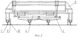
Фиг.3 - передвижной агрегат для точной установки брусьев.Figure 3 - mobile unit for the exact installation of the bars.
Фиг.4 - передвижной агрегат, несущий бункера со скреплениями.Figure 4 - mobile unit carrying a hopper with fasteners.
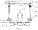
Фиг.5 - подъемная люлька для операторов в рабочем положении.5 is a lifting cradle for operators in the working position.
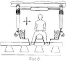
Фиг.6 - подъемная люлька для операторов в поднятом положении.6 is a lifting cradle for operators in the raised position.
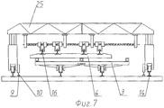
Фиг.7 - передвижной агрегат для установки рельсов по колее и ординатам.7 is a mobile unit for installing rails on a rut and ordinates.
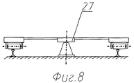
Фиг.8 - поворотное устройство.Fig - rotary device.
На фиг.1 и фиг.2 показана схема расположения заявляемой поточной линии для сборки стрелочных переводов, на которой сборка стрелочных переводов осуществляется на пяти позициях (II-VI), а позиции I и VII - вспомогательные. На поз. I размещен на рельсовом пути 1 склад 2 сменных тележек 3 с разным расположением продольных опор для разных типов стрелочных переводов, из которых собирается сплотка тележек на определенный тип стрелочного перевода. Поз. II предназначена для размещения, например, сплотки тележек 3, на которую предварительно, в требуемой последовательности со сдвигом, раскладываются брусья 4 с помощью крана 5, перемещаемого на подкрановом пути 6. На поз. III расположен объемлющий путь 7 для перемещения по нему передвижного агрегата 8 (фиг.3), предназначенного для установки брусьев 4 по эпюре и "шнуру". Для позиционирования агрегата 8 используется, например, стационарно уложенная цепь 9 и перекатываемая по ней звездочка 10. Здесь же размещен передвижной агрегат 11 (фиг.4), несущий бункера с запасом элементов скреплений 12 и рабочие места операторов 13. Поз. III может быть размещена в цеховом помещении 14. Поз. IV предназначена для раскладки на железобетонные брусья 4 с помощью крана 5 или крана 15 тяжелых металлических элементов, крестовины (на черт. не показаны) и рельсов 16. На поз. V, которую также возможно разместить в цехе 17, на объемлющем пути 18 размещен передвижной бункер 19 сборок закладных и клеммных болтов с подъемными люльками 20 для операторов, предназначенными для удобства выполнения операций вставления сборок закладных и клеммных болтов (фиг.5, 6). Каждая подъемная люлька 20, которых может быть, например, две, размещена внутри рельсовой колеи стрелочного перевода, подвешена к бункеру 19 на подвесках 21 и имеет направляющие ролики 22 для упора в рельсы 16 стрелочного перевода при опускании люльки 20 в рабочее положение силовыми цилиндрами 23, которые предназначены и для подъема люльки 20 над рельсами 16 при ее перемещении вместе с бункером 19 к следующему брусу 4. Силовой цилиндр 24, закрепленный на бункере 19, предназначен для перемещения люльки 20 поперек колеи для ориентирования ее положения (места оператора) относительно обрабатываемого бруса 4. На поз. V на объемлющем пути 18 также размещены передвижной агрегат 25 (фиг.7) для установки рельсов по колее и ординатам, для позиционирования которого используется, например, стационарно уложенная цепь 9 и перекатываемая по ней звездочка 10, и передвижной агрегат 26 для завинчивания гаек клеммных и закладных болтов. Поз. VI предназначена для расстыковывания рельсов 16 при разделении собранного стрелочного перевода на блоки и их отгрузки (на черт. не показано). На поз. VII смонтировано поворотное устройство 27 типа карусель (фиг.8), предназначенное для разворота, при необходимости, блока стрелочного перевода в зависимости от направления его укладки в путь. Возвратный путь 28 предназначен для размещения освобожденной от стрелочного перевода сплотки тележек 3 с помощью крана 15, по которому сплотка тележек 3 возвращается на исходную позицию, где краном 5 устанавливается на рельсовый путь 1 к поз. II. Проходной путь 29 предназначен для подачи материалов собираемого стрелочного перевода и уборки готовых блоков собранного стрелочного перевода. В зависимости от путевого развития предназначение путей 28 и 29 может поменяться.Figure 1 and figure 2 shows the location of the inventive production line for the assembly of turnouts, in which the assembly of turnouts is carried out in five positions (II-VI), and positions I and VII are auxiliary. On pos. I located on the rail track 1 warehouse 2
Работа поточной линии для сборки стрелочных переводов осуществляется следующим образом.The work of the production line for the assembly of switches is as follows.
На поз. II с возвратного пути 28 подается сплотка тележек 3, перегруженная краном 5, перемещаемым на подкрановом пути 6, на рельсовый путь 1. Далее, если собирается такой же стрелочный перевод, краном 5 на сплотку тележек 3 предварительно раскладывают в требуемой последовательности, с некоторым забегом вперед, комплект железобетонных брусьев 4 для одного стрелочного перевода (на фиг.1 штрихом показано требуемое положение бруса 4). Затем сплотка тележек 3 с комплектом брусьев 4, предварительно разложенных в требуемой последовательности, перемещают на поз. III (привод перемещения на черт. не показан). В том случае, если необходимо собрать стрелочный перевод другого типа (правый, левый, симметричный, двойной перекрестный), часть тележек в сплотке тележек 3 заменяют сменными тележками со склада 2 на поз. I краном 5 и собирают новую сплотку тележек и уже на нее предварительно раскладывают в требуемой последовательности, с некоторым забегом вперед, комплект железобетонных брусьев 4 для одного стрелочного перевода и перемещают на поз. III. На освободившееся место на поз. II на рельсовый путь 1 краном 5 подается освободившаяся, например, сплотка тележек 3 с возвратного пути 28, или, в зависимости от типа собираемого стрелочного перевода, со склада 2 сменных тележек производят замену некоторых тележек на сменные, собирают новую сплотку тележек и предварительно раскладывают в требуемой последовательности комплект брусьев 4 для следующего стрелочного перевода. На поз. III, в это время (фиг.3), перемещаяется по объемлющему пути 7 по заданной программе позиционирования, считываемой с помощью, например, вала со звездочкой 10, перекатываемой по стационарно уложенной цепи 9, передвижной агрегат 8 точной установки брусьев по эпюре и "шнуру". Здесь же, на поз. III, по объемлющему пути 7 перемещается агрегат 11 (фиг.4), на котором размещены бункеры 12 с элементами скреплений и рабочие места операторов 13. Каждый железобетонный брус 4, при его ориентировании, поднимается на некоторую высоту для удобства выполнения работы операторов (на черт. не показан). Поз. III может быть размещена в цеховом помещении 14. Сплотку тележек 3 с точно установленными на ней брусьями 4 перемещают на поз. IV, где с помощью крана 5 или крана 15, перемещаемого на подкрановом пути 6, на брусья 4 раскладывают тяжелые металлические детали, крестовину и рельсы 16. После этого сплотка тележек 3 перемещается на поз. V, где рельсы 16 состыковывают и производят вставление сборок закладных и клеммных болтов. В связи с тем, что эту операцию, выполняемую вручную, сложно и неудобно выполнять, перешагивая через железобетонные брусья и рельсы, она производится операторами, находящимися на подъемных люльках 20 (фиг.5, 6). Каждая люлька 20, размещенная внутри рельсовой колеи стрелочного перевода, подвешена к бункеру 19 на подвесках 21. В рабочее положение подъемную люльку 20 опускают с помощью силовых цилиндров 23, направляющие ролики 22, упираясь в рельсы 16 стрелочного перевода, определяют положение люльки на рельсах 16. Ориентирование положения подъемной люльки 20 (места оператора) относительно обрабатываемого бруса 4 производят движениями поперек колеи с помощью силового цилиндра 24, закрепленного на бункере 19. По окончании операции по вставлению сборок закладных и клеммных болтов на брусе 4 люльки 20 поднимают силовыми цилиндрами 23 над рельсами 16 и перемещают вместе с бункером 19 к следующему брусу 4. Использование подъемных люлек 20 позволяет операторам занять удобную позу при вставлении сборок закладных и клеммных болтов, что улучшает условия труда операторов. Следом перемещается агрегат 25, с помощью которого рельсы 16 устанавливают по колее и ординатам в соответствии с программным устройством, например вала со звездочкой 10, перекатываемой по стационарно уложенной цепи 9 (фиг.7). Закрепляют рельсы 16 посредством завинчивания гаек клеммных и закладных болтов гайковертами, расположенными на передвижном агрегате 26. Поз. V также может быть размещена в закрытом помещении 17. Собранный стрелочный перевод перемещают на поз. VI, где рельсы 16 стрелочного перевода расстыковывают, разделяя тем самым стрелочный перевод на блоки (эта операция может выполняться и на поз. V). Блоки стрелочного перевода краном 15 перегружают на склад или на спецсостав на проходном пути 29. Освободившаяся сплотка тележек 3 также с помощью крана 15 переставляется на возвратный путь 28 и перемещается к поз. II. Для уменьшения количества сменных тележек и количества программ при сборке тех же типов и марок стрелочных переводов блоки стрелочного перевода обратного направления (четное - нечетное), подают на установленное в конце линии поворотное устройство 27, например, типа карусель, на котором поданный краном каждый блок перед отгрузкой разворачивают. Работа по сборке на всех позициях производится одновременно, поэтому время сборки стрелочного перевода равно времени выполнения операций на одной из позиций, наибольшей по времени.On pos. II from the return path 28, a raft of
Claims (1)
Priority Applications (1)
| Application Number | Priority Date | Filing Date | Title |
|---|---|---|---|
| RU2008146340/11A RU2385373C1 (en) | 2008-11-24 | 2008-11-24 | Production assembly line of track switches |
Applications Claiming Priority (1)
| Application Number | Priority Date | Filing Date | Title |
|---|---|---|---|
| RU2008146340/11A RU2385373C1 (en) | 2008-11-24 | 2008-11-24 | Production assembly line of track switches |
Publications (1)
| Publication Number | Publication Date |
|---|---|
| RU2385373C1 true RU2385373C1 (en) | 2010-03-27 |
Family
ID=42138411
Family Applications (1)
| Application Number | Title | Priority Date | Filing Date |
|---|---|---|---|
| RU2008146340/11A RU2385373C1 (en) | 2008-11-24 | 2008-11-24 | Production assembly line of track switches |
Country Status (1)
| Country | Link |
|---|---|
| RU (1) | RU2385373C1 (en) |
Cited By (2)
| Publication number | Priority date | Publication date | Assignee | Title |
|---|---|---|---|---|
| RU2715318C1 (en) * | 2019-07-01 | 2020-02-26 | Федеральное государственное казённое военное образовательное учреждение высшего образования "Военная академия материально-технического обеспечения им. генерала армии А.В. Хрулёва" Министерства обороны Российской Федерации | Method of separate long-term storage of rail-and-sleeper grid elements of railroad on wooden sleepers |
| RU2724078C1 (en) * | 2019-07-01 | 2020-06-19 | Федеральное государственное казённое военное образовательное учреждение высшего образования "Военная академия материально-технического обеспечения им. генерала армии А.В. Хрулёва" Министерства обороны Российской Федерации | Method of separate long-term storage of elements of single railway switchover on wooden sleepers |
Citations (3)
| Publication number | Priority date | Publication date | Assignee | Title |
|---|---|---|---|---|
| SU1093740A1 (en) * | 1983-01-11 | 1984-05-23 | Донецкое Отделение Всесоюзного Проектного И Научно-Исследовательского Института Промышленного Транспорта | Bench for assembling switch points |
| FR2546924A1 (en) * | 1983-06-03 | 1984-12-07 | Matisa Materiel Ind Sa | RAILWAY MACHINE FOR LAYING AND DEPOSITING SECTIONS OR ASSEMBLED TRACKS |
| RU2007507C1 (en) * | 1991-07-04 | 1994-02-15 | Проектно-конструкторско-технологическое бюро путевых машин Хабаровского института инженеров железнодорожного транспорта | Stand for assembly of switches |
-
2008
- 2008-11-24 RU RU2008146340/11A patent/RU2385373C1/en not_active IP Right Cessation
Patent Citations (3)
| Publication number | Priority date | Publication date | Assignee | Title |
|---|---|---|---|---|
| SU1093740A1 (en) * | 1983-01-11 | 1984-05-23 | Донецкое Отделение Всесоюзного Проектного И Научно-Исследовательского Института Промышленного Транспорта | Bench for assembling switch points |
| FR2546924A1 (en) * | 1983-06-03 | 1984-12-07 | Matisa Materiel Ind Sa | RAILWAY MACHINE FOR LAYING AND DEPOSITING SECTIONS OR ASSEMBLED TRACKS |
| RU2007507C1 (en) * | 1991-07-04 | 1994-02-15 | Проектно-конструкторско-технологическое бюро путевых машин Хабаровского института инженеров железнодорожного транспорта | Stand for assembly of switches |
Cited By (2)
| Publication number | Priority date | Publication date | Assignee | Title |
|---|---|---|---|---|
| RU2715318C1 (en) * | 2019-07-01 | 2020-02-26 | Федеральное государственное казённое военное образовательное учреждение высшего образования "Военная академия материально-технического обеспечения им. генерала армии А.В. Хрулёва" Министерства обороны Российской Федерации | Method of separate long-term storage of rail-and-sleeper grid elements of railroad on wooden sleepers |
| RU2724078C1 (en) * | 2019-07-01 | 2020-06-19 | Федеральное государственное казённое военное образовательное учреждение высшего образования "Военная академия материально-технического обеспечения им. генерала армии А.В. Хрулёва" Министерства обороны Российской Федерации | Method of separate long-term storage of elements of single railway switchover on wooden sleepers |
Similar Documents
| Publication | Publication Date | Title |
|---|---|---|
| US9428372B2 (en) | Support assembly | |
| CA2751533C (en) | Apparatus and method for the handling of railway sleepers | |
| RU2385373C1 (en) | Production assembly line of track switches | |
| CN112878120A (en) | Mechanical replacing and laying construction method for ballast turnout | |
| US11976424B2 (en) | Railroad maintenance systems and methods | |
| US7370586B2 (en) | Rail track delivery and removal | |
| AU2014249695B2 (en) | System for guiding rails on a rail train | |
| RU2373319C1 (en) | Flow line for assembly of point switches of railway track | |
| JP3985979B2 (en) | Tunnel repair widening device | |
| CA2707321C (en) | Method for the installation of slab tracks in twin tube tunnels | |
| RU2210654C2 (en) | Continuous line for repair of track skeleton links | |
| CN119121709A (en) | A wheel guard rail type ballastless track bed construction method | |
| RU185951U1 (en) | INTERCONNECT TRANSFER AND CONNECTING DEVICE | |
| US6745452B1 (en) | Apparatus for assembling temporary road mats | |
| US2182057A (en) | Shifting carriage for rails and the like | |
| RU2382134C1 (en) | Method to assemble point switches | |
| RU2285080C1 (en) | Railway track skeleton automated assembly line | |
| RU2374377C2 (en) | Method for flow assembly of point switches | |
| RU2307886C1 (en) | Device for laying rails on tie baseplates, mainly for section assembling lines | |
| RU2424392C1 (en) | Method to assemble switch throws | |
| CN212375715U (en) | Bogie replacing system | |
| US3713396A (en) | Single turntable apparatus for positioning railroad ties | |
| RU2355843C1 (en) | Mobile unit for reinforced concrete beams installation in point operating gear against diagram and ordinates | |
| RU2304191C1 (en) | Production line for railroad length assemblage | |
| RU2361032C1 (en) | Line for repair of railway track lengths with reinforced concrete ties |
Legal Events
| Date | Code | Title | Description |
|---|---|---|---|
| MM4A | The patent is invalid due to non-payment of fees |
Effective date: 20111125 |