RU2383092C2 - Connector for use in field of telecommunications and connection device, including connector - Google Patents
Connector for use in field of telecommunications and connection device, including connector Download PDFInfo
- Publication number
- RU2383092C2 RU2383092C2 RU2008107933/09A RU2008107933A RU2383092C2 RU 2383092 C2 RU2383092 C2 RU 2383092C2 RU 2008107933/09 A RU2008107933/09 A RU 2008107933/09A RU 2008107933 A RU2008107933 A RU 2008107933A RU 2383092 C2 RU2383092 C2 RU 2383092C2
- Authority
- RU
- Russia
- Prior art keywords
- connector
- contacts
- capacitor
- terminals
- connection
- Prior art date
Links
Images
Classifications
-
- H—ELECTRICITY
- H01—ELECTRIC ELEMENTS
- H01R—ELECTRICALLY-CONDUCTIVE CONNECTIONS; STRUCTURAL ASSOCIATIONS OF A PLURALITY OF MUTUALLY-INSULATED ELECTRICAL CONNECTING ELEMENTS; COUPLING DEVICES; CURRENT COLLECTORS
- H01R13/00—Details of coupling devices of the kinds covered by groups H01R12/70 or H01R24/00 - H01R33/00
- H01R13/66—Structural association with built-in electrical component
- H01R13/6608—Structural association with built-in electrical component with built-in single component
- H01R13/6625—Structural association with built-in electrical component with built-in single component with capacitive component
-
- H—ELECTRICITY
- H01—ELECTRIC ELEMENTS
- H01R—ELECTRICALLY-CONDUCTIVE CONNECTIONS; STRUCTURAL ASSOCIATIONS OF A PLURALITY OF MUTUALLY-INSULATED ELECTRICAL CONNECTING ELEMENTS; COUPLING DEVICES; CURRENT COLLECTORS
- H01R13/00—Details of coupling devices of the kinds covered by groups H01R12/70 or H01R24/00 - H01R33/00
- H01R13/646—Details of coupling devices of the kinds covered by groups H01R12/70 or H01R24/00 - H01R33/00 specially adapted for high-frequency, e.g. structures providing an impedance match or phase match
- H01R13/6461—Means for preventing cross-talk
- H01R13/6464—Means for preventing cross-talk by adding capacitive elements
-
- H—ELECTRICITY
- H01—ELECTRIC ELEMENTS
- H01R—ELECTRICALLY-CONDUCTIVE CONNECTIONS; STRUCTURAL ASSOCIATIONS OF A PLURALITY OF MUTUALLY-INSULATED ELECTRICAL CONNECTING ELEMENTS; COUPLING DEVICES; CURRENT COLLECTORS
- H01R24/00—Two-part coupling devices, or either of their cooperating parts, characterised by their overall structure
- H01R24/60—Contacts spaced along planar side wall transverse to longitudinal axis of engagement
- H01R24/62—Sliding engagements with one side only, e.g. modular jack coupling devices
- H01R24/64—Sliding engagements with one side only, e.g. modular jack coupling devices for high frequency, e.g. RJ 45
Landscapes
- Details Of Connecting Devices For Male And Female Coupling (AREA)
Abstract
Description
ОБЛАСТЬ ТЕХНИКИFIELD OF TECHNOLOGY
Изобретение относится к соединительным устройствам, состоящим из двух частей, в частности к элементам конструкции соединительных устройств со встроенными электрическими элементами для подавления перекрестных помех, которые могут быть использованы в области телекоммуникаций.The invention relates to two-part connecting devices, in particular to structural elements of connecting devices with integrated electrical elements for suppressing crosstalk, which can be used in the field of telecommunications.
УРОВЕНЬ ТЕХНИКИBACKGROUND
В области техники связи и передачи и обработки данных многочисленные электрические соединения устанавливают посредством линий связи и/или линий передачи данных. Эти соединения могут быть установлены посредством проводов, например медных.In the field of communication technology and the transmission and processing of data, numerous electrical connections are established through communication lines and / or data lines. These connections can be made using wires, such as copper.
Многочисленные провода могут быть соединены с помощью соединителей, например вилок или розеток. Посредством механического соединения двух соединителей такого типа друг с другом устанавливают многочисленные электрические соединения между проводами, подсоединенными к каждому из таких соединителей. Такой тип соединения также можно использовать в электрических сетях, таких как локальные сети, для того чтобы установить любые соединения между устройствами, которые являются частью такой сети.Numerous wires can be connected using connectors, such as plugs or sockets. By mechanically connecting two connectors of this type to each other, numerous electrical connections are established between wires connected to each of these connectors. This type of connection can also be used in electrical networks, such as local area networks, in order to establish any connections between devices that are part of such a network.
В области связи и передачи данных последние достижения в ADSL-технологии позволяют передавать, по меньшей мере, два различных сигнала по одной линии связи. Происходит это посредством передачи различных сигналов на различных частотах по одной и той же линии. В частности, на стороне абонента голосовые и информационные сигналы, являющиеся разделенными, объединяются и передаются на центральную станцию посредством одной и той же линии передачи, где затем сигнал может быть разделен. Затем голосовой сигнал поступает к другому говорящему по телефону абоненту (абонентам), а информационный - другому абоненту (абонентам), который обменивается информацией. Чтобы передать абоненту голосовой и информационный сигналы, эти сигналы объединяются на центральной станции, передаются абоненту и разделяются на стороне абонента.In the field of communication and data transmission, the latest advances in ADSL technology allow the transmission of at least two different signals on the same communication line. This happens by transmitting various signals at different frequencies on the same line. In particular, on the subscriber side, voice and information signals that are separated are combined and transmitted to the central station via the same transmission line, where the signal can then be separated. Then a voice signal is sent to another telephone speaker (subscribers), and an information signal is sent to another subscriber (subscribers), who exchange information. In order to transmit voice and information signals to the subscriber, these signals are combined at the central station, transmitted to the subscriber and shared on the subscriber side.
В случае применения ADSL-технологии скорость передачи голосовых и информационных сигналов к телекоммуникационным модулям значительно возрастает, что приводит к увеличению перекрестных помех. Термин "перекрестные помехи" описывает явление, при котором контакты телекоммуникационного модуля действуют как маленькая антенна, которая передает сигнал помехи на соседние контакты. В общем случае сигналы помехи передаются парой проводов и, следовательно, парой соседних контактов. Соответственно, перекрестные помехи между контактами одной пары не являются предметом рассмотрения. Однако перекрестные помехи, возникающие между контактами соседних пар, должны подавляться насколько это возможно.When using ADSL technology, the transmission speed of voice and information signals to telecommunication modules increases significantly, which leads to an increase in crosstalk. The term “crosstalk” describes a phenomenon in which the contacts of a telecommunication module act as a small antenna that transmits an interference signal to adjacent contacts. In the general case, interference signals are transmitted by a pair of wires and, therefore, a pair of adjacent contacts. Accordingly, crosstalk between the contacts of the same pair is not the subject of consideration. However, crosstalk between the contacts of adjacent pairs should be suppressed as much as possible.
Контакты в обычных гнездовых соединителях могут быть расположены близко друг к другу. Если эти гнездовые соединители используют в системах связи с высокой производительностью, между соседними парами проводников могут появиться перекрестные помехи.Contacts in conventional female connectors can be located close to each other. If these female connectors are used in high performance communication systems, crosstalk may occur between adjacent pairs of conductors.
В патенте US 6176742 описан соединитель с компенсирующей конденсаторной сборкой, в которой каждый конденсатор имеет первую и вторую обкладки. Между выводами обкладок и отдельными контактными проводами устанавливают электрическое соединение. Однако такое соединение устанавливают на свободных концах контактных проводов. Следовательно, могут быть большие погрешности в точности взаимного расположения, и такое электрическое соединение может быть ненадежным. Эта конструкция также заявлена в качестве объекта изобретения в заявках GB 2329530 А и ЕР 1160935 А1.US Pat. No. 6,176,742 describes a connector with a compensating capacitor assembly, in which each capacitor has first and second plates. Between the terminals of the plates and the individual contact wires establish an electrical connection. However, such a connection is established at the free ends of the contact wires. Therefore, there may be large errors in the accuracy of the relative position, and such an electrical connection may be unreliable. This design is also claimed as an object of the invention in the applications GB 2329530 A and EP 1160935 A1.
В заявке US 2004/0092170 А1 описан соединитель, предназначенный для линий передачи данных, в котором некоторые контакты имеют дополнительные пластины, образующие конденсаторы. Для таких пластин необходимо много места. Кроме того, возможно повреждение в месте соединения контакта и пластины.US 2004/0092170 A1 describes a connector for data lines, in which some contacts have additional plates forming capacitors. For such plates a lot of space is needed. In addition, damage may occur at the junction of the contact and the plate.
РАСКРЫТИЕ ИЗОБРЕТЕНИЯSUMMARY OF THE INVENTION
Заявляемое изобретение описывает соединитель для использования в области телекоммуникаций, обладающий более эффективной способностью к подавлению перекрестных помех. Кроме того, заявлено соединительное устройство, включающее упомянутый соединитель и ответную часть.The claimed invention describes a connector for use in the field of telecommunications, which has a more effective ability to suppress crosstalk. In addition, a connecting device is claimed comprising said connector and a mating part.
Описанный в заявляемом изобретении соединитель, например розетка, имеет контакты, которые могут быть размещены внутри корпуса. У каждого контакта соединителя есть первый конец и второй конец. Первый конец контакта соединителя выполнен с возможностью подсоединения к нему гибкого провода кабеля связи. Второй конец контакта соединителя и/или соседний с ним участок, как правило, выполнен с возможностью установления прямого электрического соединения с контактом ответной части соединительного устройства, например вилки. Для этого контакты соединителя могут быть упругими и в свободном положении отклонены в направлении контактов ответной части. За счет этого устанавливается надежное электрическое соединение.The connector described in the claimed invention, for example a socket, has contacts that can be placed inside the housing. Each connector pin has a first end and a second end. The first end of the connector pin is configured to connect a flexible wire of a communication cable to it. The second end of the contact of the connector and / or its adjacent section, as a rule, is made with the possibility of establishing a direct electrical connection with the contact of the reciprocal part of the connecting device, such as plugs. For this, the contacts of the connector can be elastic and in the free position are rejected in the direction of the contacts of the counterpart. Due to this, a reliable electrical connection is established.
Контакты соединителя имеют, по меньшей мере, один изгиб. За счет изгиба, например, можно обеспечить вышеупомянутую упругость. Кроме того, с изгибом соединитель может оставаться небольшим, так как из-за изгиба первая контактная область, например, на первом конце, где провода подсоединяются контактами соединителя, может находиться близко ко второму концу, где контакты соединителя выполнены с возможностью установления электрического соединения с контактами ответной части. Таким образом, длина соединителя в целом может оставаться небольшой. Кроме того, изгиб можно использовать для установления надежного электрического соединения, по меньшей мере, с одним конденсатором.Connector pins have at least one bend. By bending, for example, the aforementioned elasticity can be ensured. In addition, with bending, the connector may remain small, since due to bending, the first contact region, for example, at the first end, where the wires are connected by the contacts of the connector, can be close to the second end, where the contacts of the connector are configured to make electrical connections with the contacts mate. Thus, the length of the connector as a whole can remain small. In addition, bending can be used to establish a reliable electrical connection with at least one capacitor.
Конденсатор предназначен для компенсации перекрестных помех, которые возникают между парами контактов в соединителе. Как известно специалистам в данной области техники, линии связи обычно расположены парами, и перекрестные помехи могут возникать между соседними парами. Кроме того, в некоторых случаях в соединителе контакты первой пары расположены близко к контактам второй пары, так, что перекрестные помехи с наибольшей вероятностью появляются между этими парами контактов. Для подавления перекрестных помех между этими парами один контакт каждой пары выполнен с возможностью соединения с выводами, по меньшей мере, одного конденсатора. Поскольку конденсатор, как правило, выполнен в виде двух параллельных обкладок, его выводы в общем случае соединены с каждой из них.The capacitor is designed to compensate for crosstalk that occurs between the pairs of contacts in the connector. As is known to those skilled in the art, communication lines are usually arranged in pairs, and crosstalk may occur between adjacent pairs. In addition, in some cases, in the connector, the contacts of the first pair are located close to the contacts of the second pair, so that crosstalk is most likely to occur between these pairs of contacts. To suppress crosstalk between these pairs, one contact of each pair is configured to connect to the terminals of at least one capacitor. Since the capacitor, as a rule, is made in the form of two parallel plates, its conclusions are generally connected to each of them.
Поскольку выводы конденсатора выполнены с возможностью соединения с контактами соединителя, это соединение может быть осуществлено ответной частью, вставляемой в соединитель. Таким образом, ответная часть, будучи вставленной в соединитель, воздействует на контакты соединителя, обеспечивая их соединение с выводами конденсатора.Since the terminals of the capacitor are configured to be connected to the contacts of the connector, this connection can be made by the counterpart inserted into the connector. Thus, the mating part, being inserted into the connector, acts on the contacts of the connector, ensuring their connection with the terminals of the capacitor.
Изобретение также описывает способ соединения соединителя как одной части соединительного устройства с, по меньшей мере, одной ответной частью соединительного устройства, при котором ответная часть вызывает соединение между контактами соединителя и выводами конденсатора.The invention also describes a method for connecting a connector as one part of a connecting device to at least one mating part of a connecting device, wherein the mating part causes a connection between the contacts of the connector and the terminals of the capacitor.
КРАТКОЕ ОПИСАНИЕ ЧЕРТЕЖЕЙBRIEF DESCRIPTION OF THE DRAWINGS
В дальнейшем со ссылкой на чертежи будут описаны примеры осуществления, которые, однако, не ограничивают заявленное изобретение.Hereinafter, with reference to the drawings will be described examples of implementation, which, however, do not limit the claimed invention.
На Фиг.1 схематично показано сечение вида сбоку контактов заявляемого соединителя.Figure 1 schematically shows a cross section of a side view of the contacts of the inventive connector.
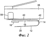
На Фиг.2 показаны контакты, изображенные на Фиг.1, в положении, когда ответная часть вставлена в соединитель.Figure 2 shows the contacts shown in figure 1, in the position when the counterpart is inserted into the connector.
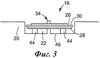
На Фиг.3 показано сечение конденсатора в заявляемом соединителе.Figure 3 shows a cross section of a capacitor in the inventive connector.
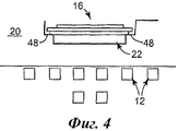
На Фиг.4 показан альтернативный вариант размещения конденсатора, показанного на Фиг.3.Figure 4 shows an alternative placement of the capacitor shown in figure 3.
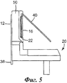
На Фиг.5 показан вид сбоку контактного держателя заявляемого соединителя.Figure 5 shows a side view of the contact holder of the inventive connector.
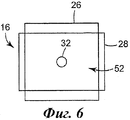
На Фиг.6 показана эффективная площадь конденсатора в первом примере размещения конденсатора в заявляемом соединителе.Figure 6 shows the effective area of the capacitor in the first example of the placement of the capacitor in the inventive connector.
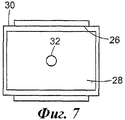
На Фиг.7 показано положение диэлектрика в конденсаторе, изображенном на Фиг.6.In Fig.7 shows the position of the dielectric in the capacitor shown in Fig.6.
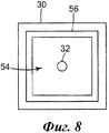
На Фиг.8 показана эффективная площадь конденсатора во втором примере размещения конденсатора в заявляемом соединителе.On Fig shows the effective area of the capacitor in the second example of the placement of the capacitor in the inventive connector.
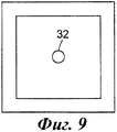
На Фиг.9 показано положение диэлектрика в конденсаторе, изображенном на Фиг.8.In Fig.9 shows the position of the dielectric in the capacitor shown in Fig.8.
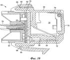
На Фиг.10 показано сечение заявляемого соединителя, выполненного в виде розетки.Figure 10 shows a cross section of the inventive connector, made in the form of a socket.
ОСУЩЕСТВЛЕНИЕ ИЗОБРЕТЕНИЯDETAILED DESCRIPTION OF THE INVENTION
Как более детально здесь будет описано, заявляемое изобретение представляет соединитель для использования в области телекоммуникаций, имеющий контакты, по меньшей мере, с одним изгибом, и, по меньшей мере, один конденсатор с выводами, выполненными с возможностью соединения с контактами соединителя в непосредственной близости к их изгибам.As will be described in more detail here, the claimed invention provides a connector for use in the field of telecommunications, having contacts with at least one bend, and at least one capacitor with terminals configured to connect to the contacts of the connector in close proximity to their bends.
Контакты соединителя могут быть выполнены любым пригодным способом, например, они могут быть выполнены из изогнутых или прямых участков проводов, например, имеющих по существу круглое поперечное сечение. В качестве альтернативы, контакты могут быть выполнены штамповкой из листового металла в форме узких полосок, которые могут быть изогнуты в одном или нескольких местах. При этом провода могут быть припаяны к контактам соединителя. В качестве альтернативы провода могут быть подсоединены к контактам соединителя методом накрутки. Также, можно обжать часть каждого контакта соединителя вокруг провода. Кроме того, контакты соединителя могут быть врезными, выполненными с возможностью прорезания изоляции провода и установления электрического соединения с электропроводящей частью провода. Наконец, зоны с врезными контактами могут быть расположены на одной или более печатных платах, на которых размещены печатные проводники, которые обеспечивают соединение между зонами с врезными контактами и контактами соединителя. При этом контакты соединителя электрически соединены с печатными проводниками, например, припаяны к ним. Таким образом, провода обычно подсоединены к первыми концами контактов соединителя.The contacts of the connector can be made in any suitable way, for example, they can be made of curved or straight sections of wires, for example, having a substantially circular cross section. Alternatively, the contacts can be stamped from sheet metal in the form of narrow strips that can be bent in one or more places. In this case, the wires can be soldered to the contacts of the connector. Alternatively, wires can be wired to the connector pins. You can also squeeze a portion of each connector pin around the wire. In addition, the contacts of the connector can be mortise, configured to cut through the insulation of the wire and establish electrical connection with the electrically conductive part of the wire. Finally, the zones with mortise contacts can be located on one or more printed circuit boards on which the printed conductors are placed, which provide a connection between the zones with mortise contacts and the contacts of the connector. In this case, the connector contacts are electrically connected to the printed conductors, for example, soldered to them. Thus, the wires are usually connected to the first ends of the contacts of the connector.
Эксперименты показали, что описанный в заявляемом изобретении соединитель соответствует категории 6, известной специалистам в данной области техники. При этом данные можно передавать в полосе частот до 250 МГц.The experiments showed that the connector described in the claimed invention corresponds to category 6, known to specialists in this field of technology. In this case, data can be transmitted in the frequency band up to 250 MHz.
Выводы конденсатора, размещенного в соединителе, выполнены с возможностью соединения с контактами соединителя. Другими словами, нет необходимости в неразрывном соединении, таком как спайка или подобном типе соединения. Вследствие механического воздействия такие соединения могут быть повреждены. Выводы конденсатора в первом положении могут быть не соединены с контактами соединителя, но соединены с ними во втором положении. Такое соединение можно, например, обеспечить посредством ответной части к соединителю. Другими словами, при установке в соединитель ответной части она может воздействовать на контакты соединителя так, что свободные концы контактов соединителя могут быть деформированы и/или смещены, по меньшей мере, они частично сдвигаются, и за счет смыкания изогнутых участков контактов соединителя с выводами конденсатора устанавливается желаемое электрическое соединение. Таким образом, можно, по меньшей мере, один конденсатор соединить с контактами соединителя и обеспечить подавление перекрестных помех, по меньшей мере, в том случае, когда в соединитель установлена его ответная часть. Выводы конденсатора, однако, также могут постоянно соприкасаться с контактами соединителя (в случае определенной погрешности изготовления контактов соединителя), то есть находиться в контакте друг с другом и до того, как в соединитель вставлена его ответная часть (например, вилка). Описанное выше упругое, или выполненное с возможностью размыкания, соединение между выводами конденсатора и контактами соединителя позволяет обеспечить соединение с различными типами ответных частей (таких как вилки) при наличии надежного электрического контакта между контактами соединителя и выводами конденсатора. Кроме того, любую допустимую погрешность выполнения любых элементов соединителя и/или его ответной части можно скомпенсировать, чтобы это не оказывало влияние на электрическое соединение между контактами соединителя и выводами конденсатора.The findings of the capacitor located in the connector are configured to connect to the contacts of the connector. In other words, there is no need for an inextricable joint such as a weld or similar type of joint. Due to mechanical stress, such compounds may be damaged. The terminals of the capacitor in the first position may not be connected to the contacts of the connector, but connected to them in the second position. Such a connection can, for example, be provided by means of a counterpart to the connector. In other words, when a mating part is installed in the connector, it can act on the connector contacts so that the free ends of the connector contacts can be deformed and / or displaced, at least partially move, and due to the closure of the curved sections of the connector contacts with the terminals of the capacitor desired electrical connection. Thus, it is possible to connect at least one capacitor to the contacts of the connector and to suppress crosstalk, at least in the case when the mating part is installed in the connector. The capacitor leads, however, can also constantly come into contact with the contacts of the connector (in the case of a certain error in the manufacture of the contacts of the connector), that is, be in contact with each other even before its counterpart (for example, a plug) is inserted into the connector. The above described elastic, or made with the possibility of opening, connection between the terminals of the capacitor and the contacts of the connector allows you to connect with various types of mating parts (such as plugs) in the presence of reliable electrical contact between the contacts of the connector and the terminals of the capacitor. In addition, any permissible error in the execution of any elements of the connector and / or its counterpart can be compensated so that this does not affect the electrical connection between the contacts of the connector and the terminals of the capacitor.
Описанное электрическое соединение между выводами конденсатора и контактами соединителя устанавливается в области изгибов контактов соединителя. Другими словами, такое электрическое соединение можно установить на некотором расстоянии от свободных концов контактов соединителя. Надежность этого электрического соединения можно повысить, потому что на него не влияет допустимая погрешность позиционирования, вибрация или им подобные характеристики свободных концов контактов соединителя. В частности, точность позиционирования контактов соединителя в области изгибов может быть обеспечена относительно легко и надежно. Таким образом, в этой области сохраняется надежное электрическое соединение с выводами конденсатора. На электрическое соединение также не влияет механическое воздействие, которое может разрушить соединение, выполненное, например, пайкой. Кроме того, при электрическом соединении с возможностью размыкания можно обойтись без затратных производственных операций, таких, которые требуются для пайки.The described electrical connection between the terminals of the capacitor and the contacts of the connector is established in the region of the bends of the contacts of the connector. In other words, such an electrical connection can be established at some distance from the free ends of the contacts of the connector. The reliability of this electrical connection can be increased because it is not affected by the permissible positioning error, vibration, or similar characteristics of the free ends of the contacts of the connector. In particular, the accuracy of positioning of the connector contacts in the bending region can be achieved relatively easily and reliably. Thus, a reliable electrical connection to the terminals of the capacitor is maintained in this area. The electrical connection is also not affected by mechanical stress, which can destroy the connection made, for example, by soldering. In addition, with an electrical connection with the possibility of opening, you can do without costly production operations, such as those required for soldering.
Когда у контактов соединителя есть изгибы, он остается компактным, при этом у контактов соединителя нет длинных участков, которые могут послужить причиной возникновения перекрестных помех. Соединение с конденсатором устанавливается непосредственно в той области, где устанавливается соединение с ответной частью соединителя, такой как вилка. Это способствует компенсации перекрестных помех. В частности, электрическое соединение с конденсатором, который установлен в непосредственной близости к изгибам, может быть в то же самое время быть установлен относительно близко к тем свободным концам контактов соединителя, где они входят в соединение с контактами ответной части. Для описанного в заявляемом изобретении соединителя не требуется печатная плата для соединения выводов конденсатора с контактами соединителя. С такой печатной платой соединитель получается сложным и дорогостоящим. В данном случае электрическое соединение, в частности между конденсатором и контактами соединителя, устанавливается напрямую через выводы конденсатора. Однако следует понимать, что в некоторых случаях описанные в заявляемом изобретении соединители могут иметь одну или более печатных плат. В частности, контакты соединителя могут, например, с их вышеуказанным первым концом, быть вставлены в печатную плату. Кроме того, на печатной плате могут быть участки с врезными контактами, для того чтобы можно было подсоединять к ним гибкие провода. Наконец, печатные проводники могут быть выполнены на печатной плате, для того чтобы соединить врезные контакты с контактами соединителя.When the contacts of the connector have bends, it remains compact, while the contacts of the connector do not have long sections that can cause crosstalk. The connection with the capacitor is established directly in the area where the connection is established with the mating part of the connector, such as a plug. This helps to compensate for crosstalk. In particular, the electrical connection with the capacitor, which is installed in close proximity to the bends, can at the same time be installed relatively close to those free ends of the contacts of the connector where they enter the connection with the contacts of the mating part. For the connector described in the claimed invention, a printed circuit board is not required to connect the capacitor leads to the contacts of the connector. With such a printed circuit board, the connector is complex and expensive. In this case, the electrical connection, in particular between the capacitor and the contacts of the connector, is established directly through the terminals of the capacitor. However, it should be understood that in some cases, the connectors described in the claimed invention may have one or more printed circuit boards. In particular, the contacts of the connector can, for example, with their aforementioned first end, be inserted into the printed circuit board. In addition, there may be sections on the printed circuit board with cut-in contacts so that flexible wires can be connected to them. Finally, the printed conductors can be made on a printed circuit board in order to connect the mortise contacts with the contacts of the connector.
Соединитель может быть особенно компактным, когда угол изгиба контактов составляет 90° или меньше. Другими словами, то, что контакты соединителя образуют острый угол, сохраняет соединитель компактным и обеспечивает, как показали эксперименты, надежное соединение с выводами конденсатора.The connector can be particularly compact when the angle of contact bending is 90 ° or less. In other words, the fact that the connector contacts form an acute angle keeps the connector compact and provides, as experiments have shown, a reliable connection to the capacitor leads.
Надежность электрического соединения также можно повысить, когда ограничена допустимая погрешность в размещении конденсатора. Такую надежность можно обеспечить, например, при оснащении соединителя контактным держателем, у которого есть, по меньшей мере, одно углубление, в котором размещают конденсатор. Конденсатор можно расположить на контактном держателе или любом другом элементе соединителя любым другим пригодным способом, например, с помощью позиционирующих штырей, уступов и т.д. Чтобы еще больше обеспечить надежность размещения контактов соединителя, их можно прикрепить к контактному держателю. В частности, вышеупомянутое углубление для размещения, по меньшей мере, одного конденсатора может быть выполнено в направляющей, которая может служить для размещения контактов соединителя.The reliability of the electrical connection can also be improved when the permissible error in the placement of the capacitor is limited. Such reliability can be achieved, for example, by equipping the connector with a contact holder, which has at least one recess in which the capacitor is placed. The capacitor can be placed on the contact holder or any other element of the connector in any other suitable way, for example, using positioning pins, ledges, etc. To further ensure the reliability of the placement of the connector pins, they can be attached to the contact holder. In particular, the aforementioned recess for accommodating at least one capacitor may be provided in a guide, which may serve to accommodate the contacts of the connector.
Однако углубление для размещения, по меньшей мере, одного конденсатора также может быть выполнено за пределами направляющей. В любом случае направляющие могут быть выполнены в виде углублений с перемычками, буртиками, перегородками или стенками между углублениями. Высоту перемычек можно уменьшить, по меньшей мере, вдоль некоторых участков, чтобы выполнить углубление, в котором можно разместить конденсатор, на одной или более таких перемычках.However, a recess for accommodating at least one capacitor can also be made outside the guide. In any case, the guides can be made in the form of recesses with jumpers, flanges, partitions or walls between the recesses. The height of the jumpers can be reduced at least along some sections to make a recess in which the capacitor can be placed on one or more of such jumpers.
При наличии контактного держателя его можно эффективно использовать для дополнительного позиционирования контактов соединителя. В частности, эффективной оказалась конструкция контактного держателя, когда контакты соединителя размещают на внутреннем уровне, а конденсатор - на внешнем. Надежность размещения контактов соединителя и/или выводов конденсатора можно дополнительно повысить, если контактный держатель имеет направляющие, в которых размещены, по меньшей мере, участки контактов соединителя и/или выводов конденсатора.With a contact holder, it can be effectively used for additional positioning of the connector pins. In particular, the design of the contact holder turned out to be effective when the connector contacts are placed at the internal level, and the capacitor is placed at the external level. The reliability of the placement of the contacts of the connector and / or the terminals of the capacitor can be further enhanced if the contact holder has guides in which at least portions of the contacts of the connector and / or the terminals of the capacitor are located.
Была признана эффективной конструкция, состоящая, по меньшей мере, из одного конденсатора, имеющего две по существу параллельные пластины, разделенные изолирующим или диэлектрическим слоем. Электрическая емкость конденсатора определяется площадью отделенных друг от друга электропроводящих обкладок и значением диэлектрической проницаемости диэлектрического слоя. Конденсатор такого типа можно выполнить в виде изготовленных из листового металла или металлической фольги обкладок, размещенных с обеих сторон диэлектрического материала. Альтернативно, конденсатор может иметь неметаллическую фольгу, металлизированную с обеих сторон. Конденсаторы такой конструкции можно производить экономичным способом, используя непроводящую фольгу или пленку, поскольку слой диэлектрика обеспечивает примерно одинаковое расстояние между обкладками, что приводит к меньшему разбросу значений емкости между различными конденсаторами. Другими словами, на емкость можно влиять, выбирая подходящий диэлектрический материал и/или подходящую толщину этого материала. Для изготовления, по меньшей мере, одного конденсатора предпочтительным материалом диэлектрика оказался материал в виде пленки. Дополнительно, можно задать величину емкости конденсатора с низкой допустимой погрешностью посредством регулирования площади токопроводящих обкладок. В одном примере выполнения конденсатора, по меньшей мере, одна из обкладок конденсатора больше другой обкладки, по меньшей мере, с одной из ее сторон. В частности, обкладки могут быть соединены таким образом, что первая обкладка больше второй с одних противоположных сторон, а вторая обкладка больше первой с других двух противоположных сторон. В качестве альтернативы, размеры одной обкладки могут быть больше в одном или двух направлениях так, что большая пластина выступает за одну или более сторон меньшей обкладки.An arrangement consisting of at least one capacitor having two substantially parallel plates separated by an insulating or dielectric layer has been found to be effective. The electric capacitance of the capacitor is determined by the area of the electrically conductive plates separated from each other and the value of the dielectric constant of the dielectric layer. A capacitor of this type can be made in the form of plates made of sheet metal or metal foil placed on both sides of the dielectric material. Alternatively, the capacitor may have a non-metallic foil metallized on both sides. Capacitors of this design can be produced in an economical way using a non-conductive foil or film, since the dielectric layer provides approximately the same distance between the plates, which leads to a smaller variation in capacitance between different capacitors. In other words, the capacitance can be influenced by choosing a suitable dielectric material and / or a suitable thickness of this material. For the manufacture of at least one capacitor, the preferred dielectric material is a film material. Additionally, you can set the capacitance value of the capacitor with a low margin of error by adjusting the area of the conductive plates. In one embodiment of a capacitor, at least one of the capacitor plates is larger than the other plate, at least on one of its sides. In particular, the plates may be connected in such a way that the first plate is larger than the second from one opposite side and the second plate is larger than the first from the other two opposite sides. Alternatively, the dimensions of one cover may be larger in one or two directions so that the large plate protrudes beyond one or more sides of the smaller cover.
Что касается изготовления обкладок конденсатора, предпочтительно, если они выполнены посредством штамповки. Этот способ изготовления, во-первых, характеризуется высокой производительностью и, во-вторых, позволяет изготовить обкладки с высокой точностью. Таким образом, используя подобные технологии, можно изготавливать конденсаторы с низкой допустимой погрешностью значения емкости. Возможны другие способы изготовления обкладок конденсатора, такие как резка. Однако было установлено, что допустимая погрешность емкости конденсаторов, при изготовлении которых его обкладки выполнялись штамповкой, очень низкая, в частности меньше 0,1 пФ.As for the manufacture of capacitor plates, it is preferable if they are made by stamping. This manufacturing method, firstly, is characterized by high productivity and, secondly, it allows the manufacture of plates with high accuracy. Thus, using similar technologies, it is possible to produce capacitors with a low permissible error of the capacitance value. Other methods for manufacturing capacitor plates are possible, such as cutting. However, it was found that the permissible error in the capacitance of capacitors, in the manufacture of which its plates were stamped, is very low, in particular less than 0.1 pF.
Сборку описанного соединителя можно упростить за счет того, что конденсатор собирают предварительно и в таком виде устанавливают в соединитель. При таком способе сборки предпочтительно, чтобы конденсатор имел, по меньшей мере, одно углубление или отверстие, взаимодействующее, по меньшей мере, с одним выступом, выполненным на соединителе. Выступом, например, может быть штырь, размещаемый в отверстии, которое выполнено в конденсаторе, когда конденсатор монтируется в соединитель.The assembly of the described connector can be simplified due to the fact that the capacitor is pre-assembled and in this form is installed in the connector. With this assembly method, it is preferable that the capacitor has at least one recess or hole that interacts with at least one protrusion made on the connector. The protrusion, for example, may be a pin placed in a hole that is formed in the capacitor when the capacitor is mounted in the connector.
Очевидно, что упругость контактов соединителя и выводов конденсатора не является необходимым требованием для того, чтобы обеспечить желаемое соединение контактов соединителя с выводами конденсатора. Однако надежность такого соединения можно повысить за счет упругости контактов соединителя и/или выводов конденсатора. За счет упругости контактов соединителя, кроме того, можно повысить надежность электрического соединения с контактами ответной части.Obviously, the elasticity of the contacts of the connector and the terminals of the capacitor is not a necessary requirement in order to provide the desired connection of the contacts of the connector with the terminals of the capacitor. However, the reliability of such a connection can be improved due to the elasticity of the contacts of the connector and / or the terminals of the capacitor. Due to the elasticity of the contacts of the connector, in addition, it is possible to increase the reliability of the electrical connection with the contacts of the mate.
В общем случае выводы конденсатора могут быть любой приемлемой формы. Однако их конструкция остается простой, когда они выполнены по существу прямыми. Предпочтительно, когда выводы конденсатора выполнены с возможностью соединения их свободных концов с контактами соединителя. Когда такое соединение устанавливается в непосредственной близости от изгибов контактов соединителя, признано предпочтительным, если выводы конденсатора имеют, например, на их свободных концах, по меньшей мере, один изогнутый участок. Такой изогнутый участок может, по меньшей мере, при соединении по существу соответствовать изгибу контакта соединителя, так, что образуется относительно большая контактная область, в которой устанавливается надежное электрическое соединение.In general, the capacitor leads can be of any acceptable shape. However, their design remains simple when they are made substantially straight. Preferably, when the terminals of the capacitor are configured to connect their free ends with the contacts of the connector. When such a connection is established in close proximity to the bends of the contacts of the connector, it is considered preferable if the terminals of the capacitor have, for example, at their free ends, at least one curved section. Such a bent portion may, at least when connected, substantially correspond to the bend of the connector contact, so that a relatively large contact area is formed in which a reliable electrical connection is established.
В общем случае в заявляемом соединителе количество контактов не ограничено каким-либо определенным числом. Однако в отдельных случаях предпочтительно, чтобы соединитель имел восемь парных контактов. В таком примере осуществления изобретения можно применить отдельный конденсатор, который имеет два вывода, выполненных с возможностью соединения с третьим и пятым контактами соединителя, в таком варианте размещения первый и второй контакты образуют первую пару, третий и шестой - вторую, четвертый и пятый - третью, а седьмой и восьмой - образуют четвертую пару (описан в EIA/TI568A).In the General case, in the inventive connector, the number of contacts is not limited to any specific number. However, in some cases, it is preferable that the connector has eight paired contacts. In such an embodiment of the invention, it is possible to use a separate capacitor, which has two terminals configured to connect to the third and fifth contacts of the connector, in this embodiment, the first and second contacts form the first pair, the third and sixth - the second, fourth and fifth - the third, and the seventh and eighth form the fourth pair (described in EIA / TI568A).
Так как описанную конструкцию соединителя также можно применять в соединительных устройствах вилочного типа, предусмотрено выполнение заявляемого соединителя в виде розетки, в которую может быть вставлена ответная часть - вилка.Since the described construction of the connector can also be used in connecting devices of the fork type, it is provided that the inventive connector is designed as a socket into which the mating part, the plug, can be inserted.
Соединение, по меньшей мере, одного конденсатора и контактов соединителя образуется, когда обе части соединительного устройства соединятся друг с другом. Соответственно, другим объектом заявляемого изобретения является соединительное устройство, включающее, по меньшей мере, один соединитель, выполненный, как описано выше, и, по меньшей мере, одну ответную часть к соединителю.The connection of at least one capacitor and the contacts of the connector is formed when both parts of the connecting device are connected to each other. Accordingly, another object of the claimed invention is a connecting device comprising at least one connector, made as described above, and at least one counterpart to the connector.
Ответной частью к соединителю, который предпочтительно является розеткой, например, может быть вилка.The counterpart to the connector, which is preferably a socket, for example, may be a plug.
Как показано на сечении вида сбоку, изображенном на Фиг.1, контакты 12 описанного в заявляемом изобретении соединителя выполнены с изгибом, образующим в показанном примере осуществления изобретения острый угол между первым участком 38 и вторым участком 40 контакта 12 соединителя. Изгиб выполнен изогнутым, закругленным или дугообразным, как показано на Фиг.1. Первый участок 38 контакта выполнен с возможностью подсоединения к нему проводов (не показаны), как будет описано более детально на Фиг.10, и, как показано в примере осуществления изобретения, этот участок несколько короче второго участка 40. Однако первый участок 38 может иметь длину приблизительно такую же или больше длины второго участка 40. Второй участок 40 контакта выполнен с возможностью установления электрического соединения, предпочтительно непосредственного электрического соединения, с контактами ответной части (см. Фиг.2 с контактами 58 ответной части 36). Конденсатор обозначен цифрой 16 и имеет выводы, из которых только один вывод 18 показан на Фиг.1. Вывод 18 выполнен по существу прямым, отчасти короче первого участка 38 контакта, по существу параллельным ему, и имеет изогнутый участок 42 на своем свободном конце. Изогнутый участок в показанном примере осуществления изобретения по существу согласован с изгибом 14 контакта и образует угол приблизительно в 120°. Этот угол также может быть меньше.As shown in the cross section of the side view shown in FIG. 1, the
Как показано на Фиг.2, это согласование помогает образовать контактную зону, которая в показанном примере осуществления изобретения проходит вдоль значительной части изгиба 14 и изогнутого участка 42. Как особенно видно на Фиг.2, когда в соединитель, выполненный в виде розетки, вставляется ответная часть - вилка 36, в показанном примере осуществления изобретения вилка начинает давить на второй участок 40 контактов 12 соединителя по направлению к первым участкам так, что эти участки в показанном примере становятся почти параллельными друг другу. Обычно упомянутые участки могут быть расположены не параллельно друг другу. Поскольку контакты 12 розетки в показанном примере упругие, они, во-первых, смещены по направлению к контактам 58 вилки 36 и устанавливают с ними надежное соединение. Во-вторых, надежное электрическое соединение устанавливается с выводами 18 конденсатора.As shown in FIG. 2, this alignment helps to form a contact zone, which, in the illustrated embodiment, extends along a significant portion of the
Как показано на Фиг.3, конденсатор 16 в показанном примере осуществления изобретения состоит из двух обкладок 26, 28 и диэлектрика, расположенного между ними. Как будет описано более детально ниже, одна из обкладок 28 может быть больше другой обкладки 26. Кроме того, диэлектрик 30 может быть больше обеих обкладок. В показанном на Фиг.3 примере конденсатор 16 имеет гнездо или отверстие (которое не видно на чертеже, отверстие 32 показано на Фиг.6-9), которое предназначено для размещения штыря 34. Штырь 34 в показанном примере выполнен на контактном держателе, описанном более детально ниже, и предназначен для размещения конденсатора 16 на контактном держателе 20. Контактный держатель 20 также имеет в показанном примере углубление 22 для размещения конденсатора 16. Кроме того, в показанном примере есть дополнительные выступающие части, выполненные в форме перегородок 44, для того чтобы отделить конденсатор 16 от стенки 46 контактного держателя. В качестве альтернативы, одна или более перегородок может быть заменена на один или более контактные столбики, штыри или подобные выступы, которые служат разделителями.As shown in FIG. 3, the
На Фиг.4 показано альтернативное выполнение углубления 22 в контактном держателе 20. В этом примере осуществления изобретения на сторонах углубления 22 есть ступеньки 48 для размещения конденсатора 16. Конденсатор размещен в предназначенном для него пространстве углубления 22 на некотором расстоянии от контактов соединителя, которые обозначены на Фиг.4 цифрой 12. Это уменьшает помехи между контактами 12 и конденсатором 16.Figure 4 shows an alternative embodiment of the
На Фиг.5 показана вся конструкция контактного держателя 20, на котором размещены контакты 12 соединителя. Как видно по первым участкам 38, по меньшей мере, эти участки, также как и изгиб 14 (виден на Фиг.1, изгиб 14 спрятан за стенкой на Фиг.5) могут быть размещены в направляющих 24, выполненных в контактном держателе 20. Направляющие 24 могут быть выполнены в форме пазов, границами которых являются перегородки или стенки, при этом одна из стенок 50 скрывает изгиб контакта 12 соединителя. Для размещения конденсатора 16 углубление 22 выполнено в контактном держателе, например, посредством уменьшения высоты перегородок или стенок, по меньшей мере, вдоль их участка. Контактный держатель 20, показанный на Фиг.5, может быть размещен в корпусе (не показан) собранного соединителя.Figure 5 shows the entire structure of the
На других чертежах показаны два примера выполнения конденсатора 16. В первом примере, показанном на Фиг.6 и 7, конденсатор 16 состоит из двух обкладок 28, 26, которые расположены в виде "креста". Другими словами, в показном примере обкладки 26, 28 выполнены прямоугольными и более длинные стороны каждой обкладки расположены по существу под прямым углом по отношению друг к другу. Таким образом, первая обкладка 26 выступает за край второй обкладки 28 в направлении вверх и вниз согласно Фиг.6, и вторая обкладка 28 выступает за край первой обкладки 26 в направлении влево и вправо. Площадь совмещения обеих обкладок, обозначенная цифрой 52, определяет эффективный конденсатор. Как показано на Фиг.7, диэлектрик 30 в показанном примере немного больше обкладки 28. На Фиг.6-9 показано отверстие 32 (в показанном примере приблизительно в центре) конденсатора 16, с которым взаимодействует штырь 34 (показан на Фиг.3).In other drawings, two examples of the execution of the
В примере, показанном на Фиг.8, первая обкладка 54 в двух перпендикулярных направлениях меньше второй обкладки 56 так, что эффективный конденсатор, т.е. там, где обкладки совмещены, образован одной меньшей обкладкой 54, потому что все стороны в показанном примере по существу параллельные. В примере, показанном на Фиг.8 и 9, диэлектрик 30 больше как меньшей обкладки 54, так и большей обкладки 56. В показанном примере обе обкладки 54 и 56 и диэлектрик 30 имеют по существу квадратную форму.In the example shown in FIG. 8, the
На Фиг.10 показано сечение заявляемого соединителя, выполненного в виде розетки 60. В показанном примере осуществления изобретения розетка 60 состоит из корпуса, у которого есть первая часть 62 корпуса и вторая часть 64 корпуса. Части 62, 64 корпуса соединены друг с другом механически, в показанном примере - посредством крюков-защелок 66. Вторая часть 64 корпуса имеет откидную крышку 70, которую можно открыть, чтобы обеспечить доступ к замкнутой полости 72 розетки 60, которая выполнена с возможностью размещения в ней вилки (не показана). Чтобы приводить крышку 70 в закрытое положение предусмотрена цилиндрическая пружина 74 с двумя плечами. Контакты 12 соединителя выведены в полость 72. На Фиг.10 контактный держатель 20, который был описан более детально выше на Фиг.5, показан вмонтированным во вторую часть 64 корпуса. По сравнению с ориентацией Фиг.5, контактный держатель видим в зеркальном отражении и повернутым на 90°.Figure 10 shows a cross section of the inventive connector, made in the form of a
В показанном примере осуществления изобретения розетка 60 имеет печатную плату 76, в которой есть отверстия, в которые вставлен конец первого участка 38 контактов соединителя. Этот конец, например, впрессован в печатную плату 76 или припаян к ней, и есть печатные проводники (не показаны), чтобы установить соединение с врезными контактами 78. Концы 80 врезных контактов также установлены в отверстия печатной платы и, например, спрессованы с печатными проводниками или припаяны к ним. Гибкие провода (не показаны) можно подсоединить к врезным контактам 78. Наконец, в показанном примере несущий элемент 82 предназначен для того, чтобы поддерживать врезные контакты 78. Это особенно предпочтительно перед тем, как стыкуются первая и вторая части корпуса. В этом положении печатная плата 76 размещена во второй части корпуса 64, концы 80 врезных контактов вставлены в печатную плату 76, когда крюки-защелки 66 второй части корпуса 64 цепляют плечи 68 первой части корпуса 62.In the shown embodiment, the
Заявленное изобретение описано со ссылкой на несколько примеров его осуществления. Предшествующее детальное описание дано только для разъяснения и без каких-либо ограничений. Например, все ссылки на стороны, плоскости и на направления приведены только в качестве примера и не ограничивают заявленное изобретение. Для специалистов в данной области технике очевидно, что можно осуществлять другие варианты, не выходя за рамки сущности изобретения. Таким образом, сущность заявляемого изобретения не следует ограничивать описанными точными деталями и структурами.The claimed invention is described with reference to several examples of its implementation. The foregoing detailed description is given for clarification only and without any limitation. For example, all references to the parties, planes and directions are given only as an example and do not limit the claimed invention. For specialists in the art it is obvious that you can implement other options without going beyond the essence of the invention. Thus, the essence of the claimed invention should not be limited to the described exact details and structures.
Claims (9)
Applications Claiming Priority (2)
| Application Number | Priority Date | Filing Date | Title |
|---|---|---|---|
| EP05017638.7 | 2005-08-12 | ||
| EP05017638A EP1753093B1 (en) | 2005-08-12 | 2005-08-12 | A telecommunications connector |
Publications (2)
| Publication Number | Publication Date |
|---|---|
| RU2008107933A RU2008107933A (en) | 2009-09-20 |
| RU2383092C2 true RU2383092C2 (en) | 2010-02-27 |
Family
ID=35826237
Family Applications (1)
| Application Number | Title | Priority Date | Filing Date |
|---|---|---|---|
| RU2008107933/09A RU2383092C2 (en) | 2005-08-12 | 2006-08-08 | Connector for use in field of telecommunications and connection device, including connector |
Country Status (13)
| Country | Link |
|---|---|
| US (1) | US7637780B2 (en) |
| EP (1) | EP1753093B1 (en) |
| JP (1) | JP4852606B2 (en) |
| AR (1) | AR054911A1 (en) |
| AT (1) | ATE405974T1 (en) |
| BR (1) | BRPI0614763A2 (en) |
| DE (1) | DE602005009179D1 (en) |
| ES (1) | ES2313165T3 (en) |
| MX (1) | MX2008001924A (en) |
| PL (1) | PL1753093T3 (en) |
| RU (1) | RU2383092C2 (en) |
| TW (1) | TW200735481A (en) |
| WO (1) | WO2007021684A1 (en) |
Cited By (1)
| Publication number | Priority date | Publication date | Assignee | Title |
|---|---|---|---|---|
| RU2476964C2 (en) * | 2011-05-27 | 2013-02-27 | Евгений Владиславович Чёрный | Method of connecting printed-circuit board to bearing structure |
Families Citing this family (11)
| Publication number | Priority date | Publication date | Assignee | Title |
|---|---|---|---|---|
| CN201112786Y (en) * | 2007-09-22 | 2008-09-10 | 富士康(昆山)电脑接插件有限公司 | Electric connector and component thereof |
| EP2045880B1 (en) | 2007-10-04 | 2011-01-26 | 3M Innovative Properties Company | A connector in the field of telecommunications |
| EP2045884B1 (en) * | 2007-10-04 | 2010-12-01 | 3M Innovative Properties Company | A shielding attachable to a connector in the field of telecommunications, a combination of a connector and at least one shielding and a method of shielding a connector |
| US7794286B2 (en) * | 2008-12-12 | 2010-09-14 | Hubbell Incorporated | Electrical connector with separate contact mounting and compensation boards |
| EP2209172A1 (en) | 2009-01-15 | 2010-07-21 | 3M Innovative Properties Company | Telecommunications Jack with a Multilayer PCB |
| GB0914025D0 (en) | 2009-08-11 | 2009-09-16 | 3M Innovative Properties Co | Telecommunications connector |
| US9343822B2 (en) | 2013-03-15 | 2016-05-17 | Leviton Manufacturing Co., Inc. | Communications connector system |
| EP3748789B1 (en) * | 2014-04-14 | 2024-05-01 | Leviton Manufacturing Company, Inc. | Communication outlet with shutter mechanism and wire manager |
| USD752590S1 (en) | 2014-06-19 | 2016-03-29 | Leviton Manufacturing Co., Ltd. | Communication outlet |
| US9608379B1 (en) | 2015-10-14 | 2017-03-28 | Leviton Manufacturing Co., Inc. | Communication connector |
| US10135207B2 (en) | 2016-01-31 | 2018-11-20 | Leviton Manufacturing Co., Inc. | High-speed data communications connector |
Family Cites Families (13)
| Publication number | Priority date | Publication date | Assignee | Title |
|---|---|---|---|---|
| US4083022A (en) * | 1976-10-12 | 1978-04-04 | Bunker Ramo Corporation | Planar pi multi-filter having a ferrite inductance for pin filters in electrical connectors |
| JPS5963526A (en) * | 1982-10-01 | 1984-04-11 | Ishikawajima Harima Heavy Ind Co Ltd | Diagnosing method of rotary machine |
| JPS5963526U (en) * | 1982-10-21 | 1984-04-26 | ティーディーケイ株式会社 | Noise filter with socket |
| GB9713849D0 (en) | 1997-06-30 | 1997-09-03 | Amp Italia | Capacitance coupled cross-talk suppressing communication connector |
| US6186834B1 (en) | 1999-06-08 | 2001-02-13 | Avaya Technology Corp. | Enhanced communication connector assembly with crosstalk compensation |
| US6176742B1 (en) | 1999-06-25 | 2001-01-23 | Avaya Inc. | Capacitive crosstalk compensation arrangement for communication connectors |
| US6238247B1 (en) * | 1999-09-22 | 2001-05-29 | Berg Technology, Inc. | Electrical connector with retaining device for releasably retaining component package therein |
| US6402560B1 (en) * | 2000-05-31 | 2002-06-11 | Avaya Technology Corp. | Communication connector with crosstalk compensation |
| US6882248B2 (en) * | 2000-09-07 | 2005-04-19 | Greatbatch-Sierra, Inc. | EMI filtered connectors using internally grounded feedthrough capacitors |
| US6773298B2 (en) * | 2002-05-06 | 2004-08-10 | Pulse Engineering, Inc. | Connector assembly with light source sub-assemblies and method of manufacturing |
| US6964587B2 (en) | 2002-11-10 | 2005-11-15 | Bel Fuse Ltd. | High performance, high capacitance gain, jack connector for data transmission or the like |
| JP3800536B2 (en) * | 2002-12-06 | 2006-07-26 | Tdk株式会社 | Modular jack |
| WO2007102893A2 (en) * | 2005-11-11 | 2007-09-13 | Greatbatch Ltd. | Tank filters placed in series with the lead wires or circuits of active medical devices to enhance mri compatibility |
-
2005
- 2005-08-12 ES ES05017638T patent/ES2313165T3/en active Active
- 2005-08-12 PL PL05017638T patent/PL1753093T3/en unknown
- 2005-08-12 AT AT05017638T patent/ATE405974T1/en not_active IP Right Cessation
- 2005-08-12 DE DE602005009179T patent/DE602005009179D1/en active Active
- 2005-08-12 EP EP05017638A patent/EP1753093B1/en not_active Not-in-force
-
2006
- 2006-08-08 BR BRPI0614763-1A patent/BRPI0614763A2/en not_active IP Right Cessation
- 2006-08-08 JP JP2008526135A patent/JP4852606B2/en not_active Expired - Fee Related
- 2006-08-08 US US11/997,966 patent/US7637780B2/en not_active Expired - Fee Related
- 2006-08-08 MX MX2008001924A patent/MX2008001924A/en active IP Right Grant
- 2006-08-08 WO PCT/US2006/030879 patent/WO2007021684A1/en active Application Filing
- 2006-08-08 RU RU2008107933/09A patent/RU2383092C2/en not_active IP Right Cessation
- 2006-08-11 AR ARP060103523A patent/AR054911A1/en unknown
- 2006-08-11 TW TW095129471A patent/TW200735481A/en unknown
Cited By (1)
| Publication number | Priority date | Publication date | Assignee | Title |
|---|---|---|---|---|
| RU2476964C2 (en) * | 2011-05-27 | 2013-02-27 | Евгений Владиславович Чёрный | Method of connecting printed-circuit board to bearing structure |
Also Published As
| Publication number | Publication date |
|---|---|
| JP2009505353A (en) | 2009-02-05 |
| AR054911A1 (en) | 2007-07-25 |
| TW200735481A (en) | 2007-09-16 |
| MX2008001924A (en) | 2008-03-24 |
| US7637780B2 (en) | 2009-12-29 |
| EP1753093A1 (en) | 2007-02-14 |
| BRPI0614763A2 (en) | 2011-04-12 |
| PL1753093T3 (en) | 2009-01-30 |
| DE602005009179D1 (en) | 2008-10-02 |
| ATE405974T1 (en) | 2008-09-15 |
| ES2313165T3 (en) | 2009-03-01 |
| EP1753093B1 (en) | 2008-08-20 |
| US20080280493A1 (en) | 2008-11-13 |
| RU2008107933A (en) | 2009-09-20 |
| JP4852606B2 (en) | 2012-01-11 |
| WO2007021684A1 (en) | 2007-02-22 |
Similar Documents
| Publication | Publication Date | Title |
|---|---|---|
| RU2383092C2 (en) | Connector for use in field of telecommunications and connection device, including connector | |
| US6431914B1 (en) | Grounding scheme for a high speed backplane connector system | |
| US7819703B1 (en) | Electrical connector configured by wafer having coupling lead-frame and method for making the same | |
| JP3831333B2 (en) | Electrical connector | |
| EP0839398B2 (en) | Electronics box coaxial connection assembly | |
| US10559928B2 (en) | Electric connector | |
| US7736176B2 (en) | Modular jack assembly having improved connecting terminal | |
| JP2910682B2 (en) | High-speed transmission connector | |
| JP2017033655A (en) | Electric connector for substrate connection | |
| KR20120022624A (en) | Electrical connector and circuit board assembly | |
| US7878850B2 (en) | Cable connector assembly with grounding device | |
| US10418756B2 (en) | Plug connector with integrated galvanic separation and shielding element | |
| US7285025B2 (en) | Enhanced jack with plug engaging printed circuit board | |
| WO2014150805A1 (en) | Multi-surface contact plug assemblies, systems and methods | |
| CN111478088A (en) | Terminal structure and connector | |
| JP2003168521A (en) | Electric connector | |
| JP5987721B2 (en) | Cable connectors and cable assemblies | |
| JP5697434B2 (en) | Shell connection structure having at least two fitting ports, shell formed by the connection structure, and connector including the shell | |
| US20210359436A1 (en) | Electrical connector assembly | |
| TW201937813A (en) | Connector for high speed signal transmission | |
| CN114421240B (en) | Shielding element and electric connector | |
| CN114421241B (en) | Electric connector and electric connector assembly | |
| CN114069283A (en) | Anti-loss transmission device set | |
| TWM637269U (en) | Plug connector | |
| CN112510396A (en) | Terminal assembly and electric connector |
Legal Events
| Date | Code | Title | Description |
|---|---|---|---|
| MM4A | The patent is invalid due to non-payment of fees |
Effective date: 20120809 |