RU2374400C1 - System for waste water lift - Google Patents
System for waste water lift Download PDFInfo
- Publication number
- RU2374400C1 RU2374400C1 RU2008122619/03A RU2008122619A RU2374400C1 RU 2374400 C1 RU2374400 C1 RU 2374400C1 RU 2008122619/03 A RU2008122619/03 A RU 2008122619/03A RU 2008122619 A RU2008122619 A RU 2008122619A RU 2374400 C1 RU2374400 C1 RU 2374400C1
- Authority
- RU
- Russia
- Prior art keywords
- tank
- reservoir
- lifting
- wastewater
- pump
- Prior art date
Links
Images


Classifications
-
- E—FIXED CONSTRUCTIONS
- E03—WATER SUPPLY; SEWERAGE
- E03F—SEWERS; CESSPOOLS
- E03F5/00—Sewerage structures
- E03F5/22—Adaptations of pumping plants for lifting sewage
-
- F—MECHANICAL ENGINEERING; LIGHTING; HEATING; WEAPONS; BLASTING
- F04—POSITIVE - DISPLACEMENT MACHINES FOR LIQUIDS; PUMPS FOR LIQUIDS OR ELASTIC FLUIDS
- F04D—NON-POSITIVE-DISPLACEMENT PUMPS
- F04D15/00—Control, e.g. regulation, of pumps, pumping installations or systems
- F04D15/02—Stopping of pumps, or operating valves, on occurrence of unwanted conditions
- F04D15/0209—Stopping of pumps, or operating valves, on occurrence of unwanted conditions responsive to a condition of the working fluid
- F04D15/0218—Stopping of pumps, or operating valves, on occurrence of unwanted conditions responsive to a condition of the working fluid the condition being a liquid level or a lack of liquid supply
Landscapes
- Engineering & Computer Science (AREA)
- Life Sciences & Earth Sciences (AREA)
- Hydrology & Water Resources (AREA)
- Public Health (AREA)
- Water Supply & Treatment (AREA)
- Mechanical Engineering (AREA)
- General Engineering & Computer Science (AREA)
- Health & Medical Sciences (AREA)
- Sewage (AREA)
- Control Of Positive-Displacement Pumps (AREA)
- Excavating Of Shafts Or Tunnels (AREA)
- Level Indicators Using A Float (AREA)
- Control Of Non-Electrical Variables (AREA)
- Processing Of Solid Wastes (AREA)
- Control Of Non-Positive-Displacement Pumps (AREA)
- Structures Of Non-Positive Displacement Pumps (AREA)
- Separation Of Suspended Particles By Flocculating Agents (AREA)
Abstract
Description
Изобретение относится к системе для подъема сточных вод, содержащей резервуар для сбора жидкостей, которыми, в частности, являются бытовые сточные воды, экскременты и т.п., и содержащей устройство для опорожнения резервуара, а этим устройством, в частности, являет насос, соединенный с электродвигателем и выполненный в виде насосной установки с приводом от электродвигателя, полностью или частично погруженной в резервуар, при этом резервуар имеет соответственно, по меньшей мере, одну впускную трубу и одну выпускную трубу для жидкостей, и система для подъема сточных вод снабжена устройством для включения и выключения насоса в зависимости от уровня жидкости в резервуаре.The invention relates to a system for lifting wastewater containing a reservoir for collecting liquids, which, in particular, are domestic wastewater, excrement, etc., and containing a device for emptying the tank, and this device, in particular, is a pump connected with an electric motor and made in the form of a pump installation driven by an electric motor, fully or partially immersed in the tank, while the tank has, respectively, at least one inlet pipe and one outlet pipe for liquids, and sys The topic for lifting wastewater is equipped with a device for turning the pump on and off depending on the liquid level in the tank.
Системы для подъема сточных вод такого типа часто используют в качестве систем для подъема экскрементов, и их применяют в зданиях и на предприятиях, когда сточные воды, подлежащие перемещению, накапливаются ниже так называемого уровня обратного потока. Уровень обратного потока обычно представляет собой уровень внешней системы отвода сточных вод, которая расположена вне здания под дорогой, по высоте. Для правильного функционирования такой системы для подъема сточных вод необходимы устройства контроля уровня жидкости в резервуаре для обеспечения способности своевременного включения и выключения насоса.Systems for lifting wastewater of this type are often used as systems for lifting excrement, and they are used in buildings and in enterprises when the wastewater to be moved accumulates below the so-called backflow level. The backflow level is usually the level of the external wastewater system, which is located outside the building under the road, in height. For the proper functioning of such a system for lifting wastewater, liquid level monitoring devices in the tank are necessary to ensure the ability to turn the pump on and off in a timely manner.
Такая система для подъема сточных вод, предназначенная для сбора и откачки сточных вод, является известной, она описана в заявке на патент Германии DE-A 3311980. Для этого в системе для подъема сточных вод имеется сборный резервуар и расположенная в нем насосная установка с приводом от электродвигателя, которая получает сигналы ее переключения через колокол пневматического управления. Он выполнен в виде трубки Пито (Pitot), объем воздуха в которой является замкнутым при повышении уровня содержимого резервуара и, следовательно, создает статическое давление в трубке Пито. Это давление регистрируют посредством датчика давления, и это значение давления преобразовывают в высоту уровня заполнения соответствующего резервуара. Однако такие системы, основанные на динамическом давлении, которые существуют в разнообразных вариантах, и их компоненты, находящиеся в резервуаре, подвержены воздействию сточных вод. Поскольку неисправность соответствующего компонента такого типа имеет существенное значение для всей системы и для всего здания, из которого она отводит сточные воды, то для обеспечения ее функционирования необходим значительный объем работ по техническому обслуживанию и текущему ремонту. Для предотвращения утечек или отложения осадка в такой системе с трубкой Пито эту трубку необходимо постоянно прочищать сложным способом посредством отдельных исполнительных элементов или же вышеупомянутые недостатки могут быть предотвращены путем введения воздушных пузырей.Such a wastewater lifting system for collecting and pumping wastewater is known, it is described in German patent application DE-A 3311980. For this, the wastewater lifting system has a collection tank and a pump unit located therein with a drive from an electric motor that receives its switching signals through a pneumatic control bell. It is made in the form of a Pitot tube (Pitot), the volume of air in which is closed with increasing level of the contents of the tank and, therefore, creates static pressure in the Pitot tube. This pressure is recorded by means of a pressure sensor, and this pressure value is converted to the height of the filling level of the corresponding reservoir. However, such systems based on dynamic pressure, which exist in various versions, and their components located in the tank, are exposed to wastewater. Since a malfunction of the corresponding component of this type is essential for the entire system and for the entire building from which it discharges waste water, a significant amount of maintenance and repair work is necessary to ensure its functioning. To prevent leaks or deposits in such a system with a pitot tube, this tube must be constantly cleaned in a complicated way using separate actuators, or the aforementioned disadvantages can be prevented by introducing air bubbles.
Известно, что альтернативой этому является использование поплавковых выключателей, описанных, например, в заявке на патент Германии DE-A 3430527, которые получили признание на рынке в качестве средства управления насосом. В зависимости от уровня жидкости в резервуаре поплавковый выключатель инициирует необходимые движения для включения и выключения насоса. Однако отложения или твердые фазы в жидкости также ограничивают функции этих поплавковых выключателей или являются фактором риска для этих функций.It is known that an alternative to this is the use of float switches, described, for example, in German patent application DE-A 3430527, which have gained market recognition as a means of controlling the pump. Depending on the liquid level in the tank, the float switch initiates the necessary movements to turn the pump on and off. However, deposits or solids in the fluid also limit the functions of these float switches or are a risk factor for these functions.
Следовательно, задачей настоящего изобретения является создание системы регистрации уровня, посредством которой может быть легко и достоверно зарегистрирован уровень заполнения резервуара и можно обойтись без сложных дополнительных защитных устройств, подвергающихся воздействию жидкости.Therefore, it is an object of the present invention to provide a level recording system by which a tank fill level can be easily and reliably recorded and complex additional protective devices exposed to liquids can be dispensed with.
Предложено следующее решение проблемы: дно резервуара или, по меньшей мере, часть площади дна резервуара выполнена таким образом, что она является упругодеформируемой в зависимости от уровня заполнения резервуара, на внешней стороне упругодеформируемой области дна резервуара расположен один или большее количество датчиков, и они измеряют его деформацию.The following solution to the problem is proposed: the bottom of the tank or at least part of the area of the bottom of the tank is made so that it is elastically deformable depending on the level of filling of the tank, one or more sensors are located on the outside of the elastically deformable region of the bottom of the tank, and they measure it deformation.
За счет такого технического решения легко решена проблема загрязнения датчиков уровня заполнения. Поскольку датчики, регистрирующие степень деформации части дна резервуара, закреплены на внешней стороне резервуара, то вредное воздействие на них сточных вод полностью исключено. В результате того, что часть дна резервуара расположена на расстоянии от площадки, на которой установлена система для подъема сточных вод, то между ними сформирована полость. Эта полость одновременно является защитным пространством, которое защищает наружные датчики от внешних механических воздействий и предотвращает повреждение упругодеформируемой части дна резервуара.Due to this technical solution, the problem of contamination of the fill level sensors is easily solved. Since the sensors that record the degree of deformation of the bottom part of the tank are fixed on the outside of the tank, the harmful effect of sewage on them is completely excluded. As a result of the fact that part of the bottom of the tank is located at a distance from the site on which the system for lifting wastewater is installed, a cavity is formed between them. This cavity is at the same time a protective space that protects the external sensors from external mechanical influences and prevents damage to the elastically deformable part of the tank bottom.
Дно резервуара или часть его площади выполнены таким образом, что, по меньшей мере, один датчик расположен в той точке измерения на дне резервуара, в которой оцениваемая деформация происходит тогда, когда резервуар заполнен до максимума. Аналогичным образом, предусмотрено наличие, по меньшей мере, одного датчика, расположенного в той точке измерения на дне резервуара, в которой оцениваемая деформация происходит тогда, когда резервуар заполнен до минимума. Соответственно, обеспечена генерация сигналов датчика, посредством которых могут быть надежно установлены необходимые моменты включения, выключения или аварийной сигнализации системы для подъема сточных вод или соединенного с ней насоса, и зависимость от соответствующего уровня заполнения резервуара. Деформация резервуара под нагрузкой не выходит за пределы допустимых значений для соответствующего материала, причем максимальная его деформация здесь происходит в точке измерения. Это достигнуто путем придания надлежащей формы дну резервуара или его части.The bottom of the tank or part of its area is designed in such a way that at least one sensor is located at that measuring point on the bottom of the tank at which the estimated deformation occurs when the tank is filled to the maximum. Similarly, it is provided that at least one sensor is located at that measurement point on the bottom of the tank at which the estimated deformation occurs when the tank is filled to a minimum. Accordingly, the generation of sensor signals is provided, by which the necessary moments of turning on, turning off or alarming the system for lifting wastewater or a pump connected to it can be reliably set, and the dependence on the corresponding tank filling level. The deformation of the tank under load does not exceed the permissible values for the corresponding material, and its maximum deformation here occurs at the measurement point. This is achieved by shaping the bottom of the tank or part thereof.
Также возможен вариант, в котором на дне резервуара расположен упругодеформируемый элемент, герметично прикрепленный к нему таким образом, что обеспечена его гибкость, и соединенный, по меньшей мере, с одним датчиком. Сигнал датчика, свидетельствующий о превышении соответствующего уровня заполнения, подвергают обработке посредством блоков оценки (по существу, являющихся известными) в системе управления насосом, которые имеются в таких системах для подъема сточных вод.An option is also possible in which an elastic deformable element is located at the bottom of the tank and is hermetically attached to it in such a way that its flexibility is ensured and connected to at least one sensor. The sensor signal, which indicates the excess of the corresponding fill level, is processed by evaluation units (essentially known) in the pump control system, which are available in such systems for lifting wastewater.
Согласно другому варианту осуществления изобретения, один или большее количество датчиков закреплены таким образом, что являются съемными. Это может быть реализовано посредством простых соединений в виде защелок-фиксаторов или зажимов и упрощает изготовление, что в то же самое время облегчает замену датчика при возможном техническом обслуживании.According to another embodiment of the invention, one or more sensors are fixed in such a way that they are removable. This can be realized through simple connections in the form of latches, clamps or clamps and simplifies the manufacture, which at the same time facilitates the replacement of the sensor with possible maintenance.
Ниже приведено более подробное описание иллюстративного примера варианта осуществления настоящего изобретения, представленного на чертежах, на которых изображено следующее:The following is a more detailed description of an illustrative example of an embodiment of the present invention shown in the drawings, which depict the following:
на Фиг.1 показана схема монтажа системы для подъема сточных вод,figure 1 shows the installation diagram of a system for lifting wastewater,
на Фиг.2 показан вид системы для подъема сточных вод,figure 2 shows a view of a system for lifting wastewater,
на Фиг.3 и 4 показаны схемы расположения датчиков, иfigure 3 and 4 shows the arrangement of the sensors, and
на Фиг.5 показано изображение дна в увеличенном масштабе.figure 5 shows an image of the bottom on an enlarged scale.
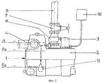
На Фиг.1 показан поперечный разрез здания, в подвале которого находится ассенизационное устройство. Сточные воды из ассенизационного устройства и другие жидкости, которые должны быть отведены, стекают в систему 1 для подъема сточных вод и собираются в ней, пока не будет достигнут достаточно высокий уровень заполнения для эпизодической перекачки. Система 1 для подъема сточных вод содержит непроницаемый для жидкости и непроницаемый для запахов резервуар 2 и расположенный герметично в нем насос 3 в виде насосной установка с приводом от электродвигателя, которая приспособлена для плавной перекачки таких жидкостей. Через впускную трубу 4 накопленные сточные воды втекают в резервуар 2, а через выпускную трубу 5 в виде напорного трубопровода их перекачивают через уровень 6 обратного потока, откуда они стекают в канализацию 7. Как правило, этот резервуар 2 снабжен вентиляцией (здесь она не показана), посредством которой обеспечивают откачку газов и предотвращают образование избыточного давления в резервуаре 2. Такой вентиляционный канал обычно выходит на крышу здания для предотвращения неприятных ощущений, вызываемых запахами.Figure 1 shows a cross section of a building, in the basement of which there is a sewage device. Wastewater from the sewage system and other liquids that must be discharged, drain into the
Такая система для подъема сточных вод из известного уровня техники показана на Фиг.2 на виде сбоку в увеличенном масштабе. Резервуар 2, в который собирают бытовые сточные воды, является герметизированным для предотвращения их утечки и для предотвращения появления источника неприятного запаха внутри здания. Резервуар 2 соединен с впускным трубопроводом 4 и с выпускным трубопроводом 5, в котором расположен обратный клапан 8 и запорный вентиль 9. В резервуар 2 частично погружен насос 3 с электрическим приводом. Он перекачивает сточные воды в выпускную трубу 5 и включается только тогда, когда это необходимо. Для этого он соединен с коммутационным устройством 10, предназначенным для управления функционированием такой системы для подъема сточных вод и для текущего контроля за ее функционированием.Such a system for lifting wastewater from the prior art is shown in FIG. 2 in an enlarged side view. The
В качестве примера, пунктирной линией показан поплавковый выключатель 11 из известного уровня техники. Такой поплавковый выключатель, расположенный в резервуаре 2, используют для передачи сигнала в коммутационное устройство 10 при достижении трех уровней РA, PE и А заполнения резервуара (которые показаны на чертеже штрихпунктирной линией), и из упомянутого коммутационного устройства инициируют выполнение функции коммутации для системы для подъема сточных вод. Самая нижняя линия РA здесь означает функцию переключения в состояние "насос выключен". В этом состоянии поплавковый выключатель, установленный с возможностью его поворота, свисает вниз. При повышении уровня жидкости поплавок перемещается вверх до тех пор, пока при уровне заполнения резервуара, равном РЕ, он не достигнет установленного положения переключения, соответствующего функции переключения в состояние "насос включен", и вызывает включение насоса коммутационным устройством 10. А когда достигнут самый высокий третий уровень А заполнения резервуара, соответствующий неразрешенному рабочему состоянию, то это инициирует включение функции аварийной сигнализации. Если в резервуар втекает объем сточных вод, превышающий тот объем, который способен откачать насос, затем функция аварийной сигнализации предотвращает затопление комнат подвала обратным потоком и предотвращает вытекание сточных вод из впускных отверстий подсоединенных устройств. Это состояние также может возникнуть в случае выхода насоса из строя. Следовательно, должны быть приняты меры для гарантии того, чтобы этот поплавковый выключатель, расположенный в резервуаре, всегда был готов к эксплуатации.As an example, the dashed line shows the
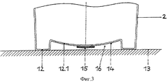
В отличие от этого, на Фиг.3 показан усовершенствованный вариант предыдущих технических решений, на этом чертеже в увеличенном масштабе изображена часть резервуара 2 на поперечном разрезе, проходящем через дно 12 резервуара. Дно 12 резервуара 2 имеет область 12.1, являющуюся его частью, которая расположена выше установочной плоскости 13 и на расстоянии от нее. В результате, между установочной плоскостью 13 и установленным на ней резервуаром 2, область 12 дна которого опирается на нее, сформирована полностью или частично замкнутая полость 16. Она защищает упругую область 12.1, являющуюся частью дна 12 резервуара, от воздействия внешних факторов. Область 12.1, являющаяся частью дна 12 резервуара, выполнена упругодеформируемой, и на ее внешней стороне 14 расположен один или большее количество датчиков 15. Расстояние между датчиком 15, установленным в самой нижней точке, и установочной плоскостью 13 имеет такую величину, что надежно предотвращает контакт резервуара 2 с установочной плоскостью 13, когда он полностью заполнен.In contrast, figure 3 shows an improved version of the previous technical solutions, this drawing on an enlarged scale shows part of the
Соответствующая степень заполнения резервуара 2 действует как столб жидкости, оказывая деформирующее воздействие на область 12.1, являющуюся частью дна, которая выполнена упругодеформируемой. Соответствующую степень ее деформации регистрируют, по меньшей мере, одним наружным датчиком 15. Его сигнал преобразовывают при помощи коммутационного устройства 10 в сигнал уровня заполнения, который отображают на дисплее и/или используют для управления насосом 3.The corresponding degree of filling of the
Вследствие достигнутого уровня жидкости в резервуаре и вследствие возникшего в результате этого столба жидкости, область дна резервуара деформируется или отклоняется иным образом. Эти деформации по порядку величины не выходят за пределы допустимых значений для соответствующего материала, используемого для резервуара 2. Таким образом, на датчик 15 оказывает воздействие работа деформации, используемая в качестве непосредственной меры уровня заполнения в резервуаре 2. Так как датчик 15 расположен в полости 16, сформированной между установочной плоскостью 13 и связанной с ней приподнятой частью 12.1 дна, то получено дополнительное защитное пространство для датчика 15. Линии передачи сигнала (на чертеже не изображены) из датчика 15 также полностью расположены вне системы для подъема сточных вод и, следовательно, легко могут быть соединены с коммутационным устройством 10. Таким образом, полностью обходятся без трубчатых изолирующих втулок в резервуаре 2, которые обычно использовали до настоящего времени. Это является дополнительным средством обеспечения безопасности для безопасной работы.Due to the achieved liquid level in the tank and due to the resulting liquid column, the bottom region of the tank is deformed or otherwise deflected. These strains, in order of magnitude, do not go beyond the permissible values for the corresponding material used for the
На Фиг.4 показан другой вариант осуществления области 12 дна. В этом варианте в упругой части 12.1 дна резервуара дополнительно предусмотрена часть 12.2 дна резервуара, имеющая упругодеформируемую конструкцию, в виде мембраны, вставленной таким образом, что она является непроницаемой для жидкости. Эта часть 12.2 дна резервуара может быть выполнена из резины, может быть выполнена в виде пластины, состоящей из эластичной пластмассы, может быть выполнена в виде металлической мембраны или в виде комбинации этих материалов. Соответствующий уровень жидкости в резервуаре 2 прогибает часть 12.2 дна резервуара по направлению к внешней стороне 14. Датчик 15, расположенный на внешней стороне 14 и функционально связанный с частью 12.2 дна резервуара, осуществляет генерацию сигнала датчика в соответствии с деформацией.Figure 4 shows another embodiment of the
На Фиг.5 показана конструкция, где датчик 15 расположен в съемном кожухе 17, который при помощи известного средства 18 может быть прикреплен к части 12.1 дна резервуара. В показанном иллюстративном варианте осуществления изобретения он одновременно служит для прикрепления части 12.2 дна резервуара. А датчик 15 может быть выполнен в виде индуктивной системы для измерения длины пути или в виде пьезокварцевого элемента для измерения давления.Figure 5 shows the design where the
Claims (6)
Приоритет установлен: от 17.12.2005 в соответствии с заявкой 102005060556.7, поданной в патентное ведомство Германии, для пп.1-6. 6. System for lifting wastewater according to any one of claims 1 or 2, characterized in that one or more sensors (15) are fixed in such a way that they are removable.
The priority is set: from 12/17/2005 in accordance with the application 102005060556.7 filed with the German Patent Office, for claims 1-6.
Applications Claiming Priority (2)
| Application Number | Priority Date | Filing Date | Title |
|---|---|---|---|
| DE102005060556.7 | 2005-12-17 | ||
| DE102005060556A DE102005060556A1 (en) | 2005-12-17 | 2005-12-17 | Sewage lifting unit |
Publications (1)
| Publication Number | Publication Date |
|---|---|
| RU2374400C1 true RU2374400C1 (en) | 2009-11-27 |
Family
ID=37766351
Family Applications (1)
| Application Number | Title | Priority Date | Filing Date |
|---|---|---|---|
| RU2008122619/03A RU2374400C1 (en) | 2005-12-17 | 2006-12-13 | System for waste water lift |
Country Status (12)
| Country | Link |
|---|---|
| US (1) | US20080310968A1 (en) |
| EP (1) | EP1960608B1 (en) |
| CN (1) | CN101331279B (en) |
| AT (1) | ATE422585T1 (en) |
| AU (1) | AU2006326327B2 (en) |
| BR (1) | BRPI0617123B1 (en) |
| DE (2) | DE102005060556A1 (en) |
| DK (1) | DK1960608T3 (en) |
| ES (1) | ES2319820T3 (en) |
| PL (1) | PL1960608T3 (en) |
| RU (1) | RU2374400C1 (en) |
| WO (1) | WO2007068455A1 (en) |
Cited By (2)
| Publication number | Priority date | Publication date | Assignee | Title |
|---|---|---|---|---|
| RU2572489C2 (en) * | 2011-02-16 | 2016-01-10 | Грундфос Менеджмент А/С | Lifting plant for waste water |
| RU2587551C2 (en) * | 2011-02-16 | 2016-06-20 | Грундфос Менеджмент А/С | Installation for sewage pumping |
Families Citing this family (9)
| Publication number | Priority date | Publication date | Assignee | Title |
|---|---|---|---|---|
| PL2447429T3 (en) * | 2010-10-27 | 2014-11-28 | Kessel Ag | Antiflooding valve |
| EP2489799B1 (en) * | 2011-02-16 | 2014-08-20 | Grundfos Management a/s | Waste water hoisting facility |
| EP2573285B1 (en) * | 2011-09-22 | 2013-10-16 | Grundfos Holding A/S | Waste water hoisting facility |
| EP2573286A1 (en) * | 2011-09-22 | 2013-03-27 | Grundfos Holding A/S | Waste water hoisting facility |
| DE102012007859B4 (en) | 2012-04-19 | 2013-12-12 | Gerhard Heiduk | Sewage lifting plant, safety device therefor and method of operation |
| DE102015204075A1 (en) * | 2015-03-06 | 2016-09-08 | Ksb Aktiengesellschaft | Plastic container with flow-guiding component |
| DE102018207257A1 (en) * | 2018-05-09 | 2019-11-14 | KSB SE & Co. KGaA | Method for operating a wastewater lifting plant |
| CN109020084A (en) * | 2018-09-03 | 2018-12-18 | 黄国治 | Sewage-treatment plant and sewage lifting system |
| CN110192830A (en) * | 2019-06-17 | 2019-09-03 | 珠海格力电器股份有限公司 | A kind of level sensing structure, liquid-level detecting method and dish-washing machine |
Family Cites Families (9)
| Publication number | Priority date | Publication date | Assignee | Title |
|---|---|---|---|---|
| US3070021A (en) * | 1960-08-10 | 1962-12-25 | Kenco Pump Divisions Of The Am | Adjustable high turn-on control |
| SE429664B (en) * | 1979-04-11 | 1983-09-19 | Electrolux Ab | DEVICE FOR COLLECTION CONTAINERS IN VACUUM DRAINAGE SYSTEM |
| DE3113903C2 (en) * | 1981-04-07 | 1985-05-09 | Werner Dipl.-Ing. 2800 Bremen Fass | Device for vacuum suction of liquids |
| US4919343A (en) * | 1989-09-25 | 1990-04-24 | Environment/One Corporation | Anti-flooding sewage grinder pump liquid level control system in separately mounted canister |
| US5152670A (en) * | 1990-04-19 | 1992-10-06 | Waldecker Donald E | Sump system |
| SE506889C2 (en) * | 1995-10-06 | 1998-02-23 | Flygt Ab Itt | Waste water pump station |
| FR2741825B1 (en) * | 1995-11-30 | 1999-04-30 | Derwent Ind Bv | ELECTRIC DRAIN GRINDER |
| CN2396117Y (en) * | 1999-11-01 | 2000-09-13 | 祝丹 | Sealed sewage lifting and delivering device |
| US7270174B2 (en) * | 2003-12-16 | 2007-09-18 | International Business Machines Corporation | Method, system and program product for automatically checking coolant loops of a cooling system for a computing environment |
-
2005
- 2005-12-17 DE DE102005060556A patent/DE102005060556A1/en not_active Withdrawn
-
2006
- 2006-12-13 AU AU2006326327A patent/AU2006326327B2/en active Active
- 2006-12-13 DE DE502006002856T patent/DE502006002856D1/en active Active
- 2006-12-13 AT AT06819027T patent/ATE422585T1/en active
- 2006-12-13 CN CN2006800474694A patent/CN101331279B/en active Active
- 2006-12-13 PL PL06819027T patent/PL1960608T3/en unknown
- 2006-12-13 EP EP06819027A patent/EP1960608B1/en active Active
- 2006-12-13 DK DK06819027T patent/DK1960608T3/en active
- 2006-12-13 RU RU2008122619/03A patent/RU2374400C1/en active
- 2006-12-13 ES ES06819027T patent/ES2319820T3/en active Active
- 2006-12-13 WO PCT/EP2006/011966 patent/WO2007068455A1/en active Application Filing
- 2006-12-13 BR BRPI0617123A patent/BRPI0617123B1/en active IP Right Grant
-
2008
- 2008-06-12 US US12/138,035 patent/US20080310968A1/en not_active Abandoned
Cited By (2)
| Publication number | Priority date | Publication date | Assignee | Title |
|---|---|---|---|---|
| RU2572489C2 (en) * | 2011-02-16 | 2016-01-10 | Грундфос Менеджмент А/С | Lifting plant for waste water |
| RU2587551C2 (en) * | 2011-02-16 | 2016-06-20 | Грундфос Менеджмент А/С | Installation for sewage pumping |
Also Published As
| Publication number | Publication date |
|---|---|
| ES2319820T3 (en) | 2009-05-12 |
| US20080310968A1 (en) | 2008-12-18 |
| CN101331279A (en) | 2008-12-24 |
| AU2006326327B2 (en) | 2011-03-03 |
| EP1960608A1 (en) | 2008-08-27 |
| WO2007068455A1 (en) | 2007-06-21 |
| DE502006002856D1 (en) | 2009-03-26 |
| ATE422585T1 (en) | 2009-02-15 |
| AU2006326327A1 (en) | 2007-06-21 |
| DE102005060556A1 (en) | 2007-08-16 |
| CN101331279B (en) | 2012-05-30 |
| DK1960608T3 (en) | 2009-05-25 |
| EP1960608B1 (en) | 2009-02-11 |
| PL1960608T3 (en) | 2009-07-31 |
| BRPI0617123B1 (en) | 2017-03-21 |
| BRPI0617123A2 (en) | 2011-07-12 |
Similar Documents
| Publication | Publication Date | Title |
|---|---|---|
| RU2374400C1 (en) | System for waste water lift | |
| DK1961963T3 (en) | Level dependent control of pumps | |
| WO1996019621A1 (en) | Improved sewage handling system | |
| RU2008117405A (en) | DEVICE FOR RE-USE OF CONTAMINATED WATER AND METHOD OF APPLICATION | |
| US20090288717A1 (en) | Basement security bucket | |
| JP2018080543A (en) | Bad odor preventing type drainage apparatus | |
| RU2411326C2 (en) | Lock of reverse head | |
| RU180748U1 (en) | SEWER PUMP INSTALLATION | |
| JP3452641B2 (en) | Domestic wastewater delivery device | |
| KR100518684B1 (en) | Atomatic Sewage Sampling System in Manhole | |
| FI57667C (en) | AUTOMATISK STYRANORDNING | |
| RU2102563C1 (en) | Sewerage pumping station | |
| CN206408734U (en) | Full-automatic filter backwashing sewage water lifting means | |
| CN207452992U (en) | Kitchen and bath's wastewater secondary utilizing device | |
| US20140251460A1 (en) | Wastewater Overflow Prevention System | |
| JP3007791B2 (en) | Automatic transfer device for liquids and other fluids | |
| KR200335202Y1 (en) | Atomatic Sewage Sampling System in Manhole | |
| CN211283705U (en) | Automatic liquid drainage device | |
| CN216381763U (en) | Sewage drainage system | |
| KR100347754B1 (en) | The collection-tank to warn a sewage-level of vacuum dump | |
| JPH11293762A (en) | Force feed equipment for sewage water | |
| JP6219766B2 (en) | Pressure drainage system | |
| JP2018090971A (en) | Pump system and odor stop type drainage equipment | |
| FI82304B (en) | Air humidifier | |
| CN112786225A (en) | Pit pump system for nuclear power plant |