RU2372535C2 - Device of increasing of thrust capacity in bearing system of rotor - Google Patents
Device of increasing of thrust capacity in bearing system of rotor Download PDFInfo
- Publication number
- RU2372535C2 RU2372535C2 RU2005100844/11A RU2005100844A RU2372535C2 RU 2372535 C2 RU2372535 C2 RU 2372535C2 RU 2005100844/11 A RU2005100844/11 A RU 2005100844/11A RU 2005100844 A RU2005100844 A RU 2005100844A RU 2372535 C2 RU2372535 C2 RU 2372535C2
- Authority
- RU
- Russia
- Prior art keywords
- rotor
- stator
- permanent magnet
- bearing system
- air gap
- Prior art date
Links
Images

Classifications
-
- F—MECHANICAL ENGINEERING; LIGHTING; HEATING; WEAPONS; BLASTING
- F16—ENGINEERING ELEMENTS AND UNITS; GENERAL MEASURES FOR PRODUCING AND MAINTAINING EFFECTIVE FUNCTIONING OF MACHINES OR INSTALLATIONS; THERMAL INSULATION IN GENERAL
- F16C—SHAFTS; FLEXIBLE SHAFTS; ELEMENTS OR CRANKSHAFT MECHANISMS; ROTARY BODIES OTHER THAN GEARING ELEMENTS; BEARINGS
- F16C39/00—Relieving load on bearings
- F16C39/06—Relieving load on bearings using magnetic means
- F16C39/063—Permanent magnets
- F16C39/066—Permanent magnets with opposing permanent magnets repelling each other
-
- F—MECHANICAL ENGINEERING; LIGHTING; HEATING; WEAPONS; BLASTING
- F16—ENGINEERING ELEMENTS AND UNITS; GENERAL MEASURES FOR PRODUCING AND MAINTAINING EFFECTIVE FUNCTIONING OF MACHINES OR INSTALLATIONS; THERMAL INSULATION IN GENERAL
- F16C—SHAFTS; FLEXIBLE SHAFTS; ELEMENTS OR CRANKSHAFT MECHANISMS; ROTARY BODIES OTHER THAN GEARING ELEMENTS; BEARINGS
- F16C32/00—Bearings not otherwise provided for
- F16C32/04—Bearings not otherwise provided for using magnetic or electric supporting means
- F16C32/0406—Magnetic bearings
- F16C32/0408—Passive magnetic bearings
- F16C32/041—Passive magnetic bearings with permanent magnets on one part attracting the other part
- F16C32/0417—Passive magnetic bearings with permanent magnets on one part attracting the other part for axial load mainly
-
- F—MECHANICAL ENGINEERING; LIGHTING; HEATING; WEAPONS; BLASTING
- F16—ENGINEERING ELEMENTS AND UNITS; GENERAL MEASURES FOR PRODUCING AND MAINTAINING EFFECTIVE FUNCTIONING OF MACHINES OR INSTALLATIONS; THERMAL INSULATION IN GENERAL
- F16C—SHAFTS; FLEXIBLE SHAFTS; ELEMENTS OR CRANKSHAFT MECHANISMS; ROTARY BODIES OTHER THAN GEARING ELEMENTS; BEARINGS
- F16C32/00—Bearings not otherwise provided for
- F16C32/04—Bearings not otherwise provided for using magnetic or electric supporting means
- F16C32/0406—Magnetic bearings
- F16C32/0408—Passive magnetic bearings
- F16C32/0423—Passive magnetic bearings with permanent magnets on both parts repelling each other
- F16C32/0427—Passive magnetic bearings with permanent magnets on both parts repelling each other for axial load mainly
-
- F—MECHANICAL ENGINEERING; LIGHTING; HEATING; WEAPONS; BLASTING
- F16—ENGINEERING ELEMENTS AND UNITS; GENERAL MEASURES FOR PRODUCING AND MAINTAINING EFFECTIVE FUNCTIONING OF MACHINES OR INSTALLATIONS; THERMAL INSULATION IN GENERAL
- F16C—SHAFTS; FLEXIBLE SHAFTS; ELEMENTS OR CRANKSHAFT MECHANISMS; ROTARY BODIES OTHER THAN GEARING ELEMENTS; BEARINGS
- F16C39/00—Relieving load on bearings
- F16C39/06—Relieving load on bearings using magnetic means
- F16C39/063—Permanent magnets
-
- F—MECHANICAL ENGINEERING; LIGHTING; HEATING; WEAPONS; BLASTING
- F16—ENGINEERING ELEMENTS AND UNITS; GENERAL MEASURES FOR PRODUCING AND MAINTAINING EFFECTIVE FUNCTIONING OF MACHINES OR INSTALLATIONS; THERMAL INSULATION IN GENERAL
- F16C—SHAFTS; FLEXIBLE SHAFTS; ELEMENTS OR CRANKSHAFT MECHANISMS; ROTARY BODIES OTHER THAN GEARING ELEMENTS; BEARINGS
- F16C2233/00—Monitoring condition, e.g. temperature, load, vibration
-
- F—MECHANICAL ENGINEERING; LIGHTING; HEATING; WEAPONS; BLASTING
- F16—ENGINEERING ELEMENTS AND UNITS; GENERAL MEASURES FOR PRODUCING AND MAINTAINING EFFECTIVE FUNCTIONING OF MACHINES OR INSTALLATIONS; THERMAL INSULATION IN GENERAL
- F16C—SHAFTS; FLEXIBLE SHAFTS; ELEMENTS OR CRANKSHAFT MECHANISMS; ROTARY BODIES OTHER THAN GEARING ELEMENTS; BEARINGS
- F16C25/00—Bearings for exclusively rotary movement adjustable for wear or play
-
- F—MECHANICAL ENGINEERING; LIGHTING; HEATING; WEAPONS; BLASTING
- F16—ENGINEERING ELEMENTS AND UNITS; GENERAL MEASURES FOR PRODUCING AND MAINTAINING EFFECTIVE FUNCTIONING OF MACHINES OR INSTALLATIONS; THERMAL INSULATION IN GENERAL
- F16C—SHAFTS; FLEXIBLE SHAFTS; ELEMENTS OR CRANKSHAFT MECHANISMS; ROTARY BODIES OTHER THAN GEARING ELEMENTS; BEARINGS
- F16C32/00—Bearings not otherwise provided for
- F16C32/04—Bearings not otherwise provided for using magnetic or electric supporting means
- F16C32/0406—Magnetic bearings
- F16C32/0408—Passive magnetic bearings
- F16C32/041—Passive magnetic bearings with permanent magnets on one part attracting the other part
- F16C32/0412—Passive magnetic bearings with permanent magnets on one part attracting the other part for radial load mainly
- F16C32/0414—Passive magnetic bearings with permanent magnets on one part attracting the other part for radial load mainly with facing axial projections
-
- Y—GENERAL TAGGING OF NEW TECHNOLOGICAL DEVELOPMENTS; GENERAL TAGGING OF CROSS-SECTIONAL TECHNOLOGIES SPANNING OVER SEVERAL SECTIONS OF THE IPC; TECHNICAL SUBJECTS COVERED BY FORMER USPC CROSS-REFERENCE ART COLLECTIONS [XRACs] AND DIGESTS
- Y10—TECHNICAL SUBJECTS COVERED BY FORMER USPC
- Y10T—TECHNICAL SUBJECTS COVERED BY FORMER US CLASSIFICATION
- Y10T29/00—Metal working
- Y10T29/49—Method of mechanical manufacture
- Y10T29/49636—Process for making bearing or component thereof
- Y10T29/49696—Mounting
Landscapes
- Engineering & Computer Science (AREA)
- General Engineering & Computer Science (AREA)
- Mechanical Engineering (AREA)
- Magnetic Bearings And Hydrostatic Bearings (AREA)
- Connection Of Motors, Electrical Generators, Mechanical Devices, And The Like (AREA)
Abstract
Description
Область техникиTechnical field
Настоящее изобретение относится к подшипниковым системам ротора. В частности, изобретение относится к устройству и способу увеличения допустимой осевой нагрузки в подшипниковой системе ротора.The present invention relates to rotor bearing systems. In particular, the invention relates to a device and method for increasing the permissible axial load in the rotor bearing system.
Предшествующий уровень техникиState of the art
В работающих на высокой скорости подшипниковых системах ротора, испытывающих значительные осевые нагрузки, т.е. когда действует значительная нагрузка, параллельная оси вращения, и толкает вал в осевом направлении, создание упорных подшипников, воспринимающих осевое усилие или давление вала, особенно в подшипниковых системах без смазки, является трудной задачей.In rotor bearing systems operating at high speed, experiencing significant axial loads, i.e. when a significant load acts parallel to the axis of rotation and pushes the shaft in the axial direction, the development of thrust bearings that absorb axial force or shaft pressure, especially in non-lubricated bearing systems, is a difficult task.
Для таких высокоскоростных систем, не имеющих смазки, используются магнитные подшипники, размер которых можно подобрать с учетом наихудших возможных рабочих условий, а также газодинамические подшипники.For such high-speed, lubricated-free systems, magnetic bearings are used, the size of which can be selected taking into account the worst possible operating conditions, as well as gas-dynamic bearings.
Для обеспечения высокой допустимой нагрузки на упорный подшипник в магнитных подшипниковых системах необходимо решить следующие конструкторские задачи:To ensure a high permissible load on the thrust bearing in magnetic bearing systems, it is necessary to solve the following design tasks:
- высокая допустимая нагрузка означает большую площадь действия усилия в валу, но площадь действия усилия ограничена максимальным наружным диаметром в связи с пределом прочности материала ротора;- high permissible load means a large area of the force in the shaft, but the area of the force is limited by the maximum outer diameter due to the tensile strength of the rotor material;
- для высокой допустимой нагрузки требуются катушки большого размера и путь магнитного потока в статоре, что обусловливает большие осевые габариты статора, и, в свою очередь, требуется более длинный ротор, но длина ротора ограничена частотой колебаний вала;- for a high permissible load, large coils and a magnetic flux path in the stator are required, which leads to large axial dimensions of the stator, and, in turn, a longer rotor is required, but the rotor length is limited by the shaft oscillation frequency;
- для катушек обычно требуется сильный ток, но однополюсный наконечник не позволяет повысить температуру в обмотке. Кроме того, наличие сильного тока предполагает использование дорогостоящей силовой электроники.- coils usually require a strong current, but a single-pole tip does not allow to increase the temperature in the winding. In addition, the presence of a strong current involves the use of expensive power electronics.
В газодинамических подшипниковых системах, таких как гидростатические или гидродинамические системы, для работающего под высокой осевой нагрузкой подшипника требуется очень большая площадь усилия, которую подчас невозможно обеспечить. В этих системах главная трудность вызвана низкой вязкостью газа, низкой относительной скоростью между ротором и подшипниками вблизи центра вращения и ограниченным обеспечиваемым давлением.In gas-dynamic bearing systems, such as hydrostatic or hydrodynamic systems, a bearing operating under high axial load requires a very large area of force, which is sometimes impossible to provide. In these systems, the main difficulty is caused by the low viscosity of the gas, the low relative speed between the rotor and bearings near the center of rotation, and the limited pressure provided.
В системах упорных подшипников с элементом качения и в системах гидростатических подшипников сильная нагрузка обусловливает рост потерь в системе, что приводит к низкому кпд и даже к перегреву системы.In thrust bearing systems with a rolling element and in systems of hydrostatic bearings, a heavy load causes an increase in losses in the system, which leads to low efficiency and even to overheating of the system.
Из вышеизложенного очевидно следует необходимость обеспечения компактного, с высоким кпд устройства и способа, обеспечивающих повышение допустимой осевой нагрузки в подшипниковой системе ротора.From the foregoing, it clearly follows the need to provide a compact, high-efficiency device and method that increase the allowable axial load in the rotor bearing system.
Краткое изложение существа изобретенияSummary of the invention
Задачей настоящего изобретения является создание усовершенствованного устройства и способа для повышения допустимой осевой нагрузки в подшипниковой системе ротора.The present invention is the creation of an improved device and method for increasing the permissible axial load in the bearing system of the rotor.
Поставленная задача согласно настоящему изобретению решена путем создания устройства для увеличения допустимой осевой нагрузки в подшипниковой системе ротора, которое содержит:The problem according to the present invention is solved by creating a device to increase the permissible axial load in the rotor bearing system, which contains:
статор, установленный на оси вращения подшипниковой системы ротора;a stator mounted on the axis of rotation of the rotor bearing system;
ротор, отделенный от статора первым воздушным зазором на оси вращения;a rotor separated from the stator by a first air gap on the axis of rotation;
по меньшей мере один постоянный магнит, отделенный от ротора вторым воздушным зазором.at least one permanent magnet separated from the rotor by a second air gap.
Устройство характеризуется тем, что по меньшей мере один постоянный магнит, статор и ротор образуют магнитную цепь, обеспечивающую путь магнитного потока, причем поток в первом и втором воздушных зазорах обеспечивает формирование компенсирующего усилия между ротором и статором, которое противодействует внешнему усилию Fext.The device is characterized in that at least one permanent magnet, stator and rotor form a magnetic circuit providing a magnetic flux path, and the flow in the first and second air gaps provides the formation of a compensating force between the rotor and the stator, which counteracts the external force F ext .
Поставленная задача решена также путем создания способа увеличения допустимой осевой нагрузки в подшипниковой системе ротора, согласно которому:The problem is also solved by creating a method of increasing the permissible axial load in the rotor bearing system, according to which:
используют статор, установленный на оси вращения подшипниковой системы ротора;use a stator mounted on the axis of rotation of the rotor bearing system;
используют ротор, отделенный от статора первым воздушным зазором на оси вращения;use a rotor separated from the stator by the first air gap on the axis of rotation;
используют по меньшей мере один постоянный магнит, отделенный от ротора вторым воздушным зазором.at least one permanent magnet is used, separated from the rotor by a second air gap.
Способ характеризуется тем, что по меньшей мере один постоянный магнит, статор и ротор образуют магнитную цепь, обеспечивающую путь магнитного потока, при этом поток в первом и втором воздушных зазорах обеспечивает формирование компенсирующего усилия между ротором и статором, которое противодействует внешнему усилию Fext.The method is characterized in that at least one permanent magnet, stator and rotor form a magnetic circuit providing a magnetic flux path, while the flux in the first and second air gaps provides the formation of a compensating force between the rotor and the stator, which counteracts the external force F ext .
Краткое описание чертежейBrief Description of the Drawings
В дальнейшем изобретение поясняется описанием предпочтительных вариантов его осуществления со ссылками на прилагаемые чертежи, на которых:The invention is further explained in the description of the preferred options for its implementation with reference to the accompanying drawings, in which:
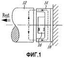
Фиг.1 изображает схему устройства для повышения допустимой нагрузки согласно первому варианту осуществления изобретения;Figure 1 depicts a diagram of a device for increasing the permissible load according to the first embodiment of the invention;
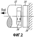
Фиг.2 - схему устройства для повышения допустимой нагрузки согласно второму варианту осуществления изобретения;Figure 2 - diagram of a device for increasing the permissible load according to the second variant embodiment of the invention;
Фиг.3 - схему устройства для повышения допустимой нагрузки согласно третьему варианту осуществления настоящего изобретения;Figure 3 - diagram of a device for increasing the permissible load according to the third variant of implementation of the present invention;
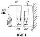
Фиг.4 - схему устройства повышения допустимой нагрузки согласно четвертому варианту осуществления изобретения;4 is a diagram of a device for increasing the allowable load according to a fourth embodiment of the invention;
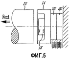
Фиг.5 - схему устройства повышения допустимой нагрузки согласно пятому варианту осуществления настоящего изобретения.5 is a diagram of a load-boosting device according to a fifth embodiment of the present invention.
Описание предпочтительных вариантов осуществления настоящего изобретенияDescription of preferred embodiments of the present invention
Согласно изобретению предложены устройство и способ для увеличения допустимой осевой нагрузки в подшипниковой системе ротора.According to the invention, a device and method are provided for increasing the permissible axial load in the rotor bearing system.
Устройство увеличения допустимой нагрузки в подшипниковой системе ротора согласно первому аспекту настоящего изобретения содержит статор и ротор, выполненные с обеспечением увеличения допустимой магнитной осевой нагрузки за счет применения нескольких постоянных магнитов, создающих силу притяжения между ротором и статором, которая противодействует усилию Fext, прилагаемому извне. Внешнее усилие Fext может быть вызвано давлением или силой тяжести при вертикальной конфигурации вала, когда центр тяжести в этой конфигурации расположен низко.The device for increasing the allowable load in the rotor bearing system according to the first aspect of the present invention comprises a stator and a rotor designed to increase the allowable magnetic axial load due to the use of several permanent magnets that create an attractive force between the rotor and the stator, which counteracts the external force F ext applied from the outside. The external force F ext can be caused by pressure or gravity in a vertical shaft configuration when the center of gravity in this configuration is low.
Устройство увеличения допустимой нагрузки содержит статор 14 (фиг.1, 2, 3) и ротор 12, выполненные с возможностью обеспечения компенсирующих усилий между статором 14 и ротором 12.The device for increasing the permissible load comprises a stator 14 (Figs. 1, 2, 3) and a
На Фиг.1 представлен первый вариант осуществления устройства увеличения допустимой нагрузки, которое содержит ротор 12, однополюсный наконечник 14 статора, постоянный магнит 16 и прокладку 18.Figure 1 presents the first embodiment of a device for increasing the permissible load, which contains a
Постоянный магнит 16 прикреплен к однополюсному наконечнику 14 статора таким образом, что постоянный магнит 16, однополюсный наконечник 14 и ротор 12 образуют магнитную цепь, причем однополюсный наконечник 14 статора и ротор 12 отделены друг от друга зазором, и также отделены друг от друга зазором ротор 12 и постоянный магнит 16.The
Сформированная таким образом магнитная цепь обеспечивает путь магнитного потока, показанного пунктирной линией. Магнитный поток в воздушных зазорах между однополюсным наконечником 14 статора и ротором 12, и ротором 12 и постоянным магнитом 16, соответственно, генерирует силу притяжения, которая в состоянии компенсировать внешнее усилие Fext.The magnetic circuit thus formed provides the path of the magnetic flux shown by the dashed line. The magnetic flux in the air gaps between the unipolar tip of the
За счет оптимизации конструктивных параметров различных выполненных из мягкого магнитного материала поверхностей полюса, магнита и воздушных зазоров можно использовать минимальный объем магнита с соблюдением ограничений по размерам и воздушным зазорам. После того как определено расположение постоянного магнита 16 по отношению к выполненным из мягкого магнитного материала полюсам, посредством прокладки 18 обеспечивается регулировка воздушных зазоров для изменения величины компенсации, поскольку известное физическое правило заключается в том, что сила действия магнитного поля возрастает с уменьшением воздушного зазора. Эта регулировка обеспечивает гибкость при использовании указанной конструкции, при изготовлении и подборе материалов, и гибкость при изменениях в технологическом процессе.By optimizing the design parameters of the various surfaces of the pole, magnet, and air gaps made of soft magnetic material, the minimum magnet volume can be used, subject to size and air gap restrictions. After the location of the
Во втором варианте осуществления (Фиг.2) устройство увеличения допустимой нагрузки в подшипниковой системе ротора в основном аналогично устройству на Фиг.1. Единственное отличие заключается в том, что магнит 16 установлен в роторе 12 и сила притяжения между ротором 12 и статором 14 создается этим магнитом 16.In the second embodiment (FIG. 2), the device for increasing the permissible load in the rotor bearing system is basically similar to the device in FIG. 1. The only difference is that the
Ротор 12 выполнен из мягкого магнитного материала, такого как углеродистая сталь. Однополюсный наконечник 14 статора также выполнен из мягкого магнитного материала, такого как мягкая сталь.The
Согласно третьему варианту осуществления (Фиг.3) сила притяжения между ротором 12 и статором 14 создается первым магнитом 16а, установленным в роторе 12, и вторым магнитом 16b, установленным в статоре 14. Каждый магнит 16а, 16b имеет полюсы разной полярности, обращенные друг к другу. Альтернативно, когда ротор 12 и статор 14 выполнены из мягких магнитных материалов, то силу притяжения между ротором 12 и статором 14 можно создать за счет расположения поверхностей полюса между ротором 12 и статором 14.According to the third embodiment (FIG. 3), the attractive force between the
Согласно второму аспекту настоящего изобретения устройство увеличения допустимой нагрузки в подшипниковой системе ротора содержит статор и ротор, выполненные с обеспечением увеличения допустимой магнитной осевой нагрузки за счет использования нескольких постоянных магнитов, создающих силу отталкивания между ротором и статором.According to a second aspect of the present invention, a device for increasing the allowable load in the rotor bearing system comprises a stator and a rotor configured to increase the allowable magnetic axial load by using several permanent magnets that create a repulsive force between the rotor and the stator.
Силу отталкивания можно сформировать первым магнитом 16а (фиг.4), установленным в роторе 12, и вторым магнитом 16b, установленным в статоре 14. При этом в магнитах 16а и 16b полюсы одинаковой полярности обращены друг к другу, например полюс N магнита 16а обращен к полюсу N магнита 16b.The repulsive force can be generated by the
Из вышеизложенного следует, что либо силу притяжения, либо силу отталкивания можно создать с помощью двух магнитов, за счет изменения расположения полярностей разных магнитов, в зависимости от направления действующих внешних сил.It follows from the foregoing that either the attractive force or the repulsive force can be created using two magnets, by changing the arrangement of the polarities of the different magnets, depending on the direction of the acting external forces.
В обоих случаях, если устройство увеличения допустимой нагрузки в подшипниковой системе ротора, согласно настоящему изобретению, содержит магнит, установленный в роторе, и магнит, установленный в статоре (Фиг.3 и Фиг.4), то ротор 12 и статор 14 могут быть выполнены из немагнитных материалов. Если в роторе 12 и статоре 14 используются мягкие магнитные материалы, то геометрию магнитов и расположение поверхностей полюса и воздушных зазоров можно оптимизировать для использования минимального объема магнитов, что обеспечивает компактность и экономию затрат. Если для статора 14 и ротора 12 используются мягкие магнитные материалы, то усилие, создаваемое в воздушном зазоре между ними, также способствует созданию компенсирующего усилия. Поэтому для магнита требуется меньшее количество материала. Но этот вариант может оказаться очень дорогостоящим, поскольку мягкие магнитные материалы могут быть довольно дорогими.In both cases, if the device for increasing the permissible load in the rotor bearing system according to the present invention contains a magnet installed in the rotor and a magnet installed in the stator (Fig. 3 and Fig. 4), then the
Прокладка 18 позволяет изменять воздушные зазоры и, таким образом, регулировать компенсирующее усилие.The
Если требуется автоматическая регулировка или регулировка на месте компенсирующего усилия, то можно использовать пьезоэлектрический исполнительный механизм 20 (фиг.5) (вместо прокладки) для регулировки воздушных зазоров, которая, в свою очередь, будет изменять компенсирующее усилие.If automatic adjustment or on-site adjustment of the compensating force is required, then the piezoelectric actuator 20 (FIG. 5) (instead of the gasket) can be used to adjust the air gaps, which, in turn, will change the compensating force.
Специалистам в данной области техники ясно, что конфигурацию, представленную на Фиг.5, можно использовать для компенсирования внешнего динамического усилия, если сигнал динамической компенсации подается на пьезоэлектрический исполнительный механизм 20.It will be apparent to those skilled in the art that the configuration shown in FIG. 5 can be used to compensate for an external dynamic force if a dynamic compensation signal is supplied to the
Для измерения компенсирующего усилия устройство увеличения допустимой нагрузки в подшипниковой системе ротора можно обеспечить устройствами 22 (фиг.5) измерения усилия, такими как тензометры или пьезоэлектрические элементы. Это целесообразно для осуществления непрерывного контроля. В активных магнитных подшипниковых системах целесообразно использовать усилие (динамическое или статическое), обеспечиваемое активным подшипником. Поэтому с помощью представленного на Фиг.5 устройства измерения усилия можно измерять усилие, компенсируемое устройством увеличения допустимой нагрузки в подшипниковой системе ротора. Таким образом, можно определить общее внешнее усилие, прилагаемое на вал.To measure the compensating force, a device for increasing the permissible load in the rotor bearing system can be provided with force measuring devices 22 (FIG. 5), such as tensometers or piezoelectric elements. It is advisable for continuous monitoring. In active magnetic bearing systems, it is advisable to use the force (dynamic or static) provided by the active bearing. Therefore, using the force measuring device shown in FIG. 5, it is possible to measure the force compensated by the device for increasing the permissible load in the rotor bearing system. Thus, the total external force exerted on the shaft can be determined.
Согласно третьему аспекту настоящего изобретения предложен способ достижения увеличения допустимой нагрузки другого уровня за счет регулирования магнитного воздушного зазора между статором и ротором. Раскрытое выше устройство увеличения допустимой нагрузки в подшипниковой системе ротора позволяет создавать усилие между статором и ротором, компенсирующее внешнее усилие Fext.According to a third aspect of the present invention, there is provided a method for achieving an increase in the allowable load of another level by adjusting the magnetic air gap between the stator and the rotor. The above-described device for increasing the permissible load in the bearing system of the rotor allows you to create a force between the stator and the rotor, compensating for the external force F ext .
Регулирование можно обеспечить посредством прокладки (Фиг.1) или автоматически посредством исполнительного механизма, например пьезоэлектрическим элементом, установленным в статоре (Фиг.5).Regulation can be ensured by laying (Fig. 1) or automatically by means of an actuator, for example, a piezoelectric element installed in the stator (Fig. 5).
Усилие, обеспечиваемое устройством увеличения допустимой нагрузки в подшипниковой системе ротора, можно измерять либо тензометром, либо пьезоэлектрическим элементом (Фиг.5).The force provided by the device for increasing the permissible load in the rotor bearing system can be measured either with a tensometer or with a piezoelectric element (Figure 5).
Способ согласно третьему аспекту настоящего изобретения предусматривает использование мягких магнитных материалов для выполнения статора и ротора, что позволяет оптимизировать применение создающих компенсирующее усилие магнитов (Фиг.1-4), или использование прокладки для регулирования компенсирующего усилия, или использование пьезоэлектрического исполнительного механизма для автоматической регулировки компенсирующего усилия (как статического, так и/или динамического), или использование тензометра или пьезоэлектрического элемента для измерения компенсирующего усилия, или установку устройства увеличения допустимой нагрузки в конце вала, в результате чего исключается необходимость модифицирования длины вала.The method according to the third aspect of the present invention provides for the use of soft magnetic materials to form the stator and rotor, which makes it possible to optimize the use of compensating force magnets (Figs. 1-4), or using a gasket to regulate the compensating force, or using a piezoelectric actuator to automatically adjust the compensating force efforts (both static and / or dynamic), or the use of a strain gauge or piezoelectric element to measure the compensating force, or to install a device to increase the permissible load at the end of the shaft, which eliminates the need to modify the length of the shaft.
Из вышеизложенного ясно, что в конструкцию можно вносить изменения согласно конкретным вариантам применения. Например, если важно свести к минимуму длину вала, то целесообразной может стать конфигурация, представленная на Фиг.1.From the foregoing it is clear that the design can be modified according to specific applications. For example, if it is important to minimize the length of the shaft, then the configuration shown in FIG. 1 may become appropriate.
Способ согласно настоящему изобретению обеспечивает возможность увеличения допустимой магнитной осевой нагрузки и при этом исключает необходимость применения твердых или жидких контактов, т.е. с помощью бесконтактных средств.The method according to the present invention provides the possibility of increasing the permissible magnetic axial load and thus eliminates the need for solid or liquid contacts, i.e. using contactless means.
Применение настоящего изобретения может быть целесообразным в системах, в которых осевое усилие является однонаправленным либо со стороны внешней рабочей нагрузки, либо со стороны веса ротора в вертикальной конфигурации.The application of the present invention may be appropriate in systems in which the axial force is unidirectional either from the side of the external working load or from the side of the weight of the rotor in a vertical configuration.
Предложенное устройство и способ увеличения допустимой нагрузки в подшипниковой системе ротора согласно настоящему изобретению можно использовать в магнитной подшипниковой системе, гидростатической подшипниковой системе, гидродинамической подшипниковой системе или подшипниковой системе с элементом качения. Например, настоящее изобретение можно использовать для компенсации однонаправленной внешней статической нагрузки, такой как рабочая нагрузка, например статическое давление, или вес вала в вертикальной конфигурации.The proposed device and method of increasing the permissible load in the rotor bearing system according to the present invention can be used in a magnetic bearing system, a hydrostatic bearing system, a hydrodynamic bearing system or a bearing system with a rolling element. For example, the present invention can be used to compensate for unidirectional external static loads, such as workloads, such as static pressures, or shaft weights in a vertical configuration.
В соответствии с настоящим изобретением можно обеспечить компактное и недорогостоящее средство для компенсации осевой нагрузки - упорный подшипник и устройство увеличения допустимой осевой нагрузки.In accordance with the present invention, it is possible to provide a compact and inexpensive means for compensating axial load - thrust bearing and a device for increasing the permissible axial load.
Можно также компенсировать динамическую нагрузку, если она измеряется и исполнительный механизм выполнен согласно Фиг.5.You can also compensate for the dynamic load, if it is measured and the actuator is made according to Fig.5.
Поскольку устройство увеличения допустимой нагрузки согласно настоящему изобретению можно установить на одном конце вала (Фиг.1-5), длину вала не нужно модифицировать.Since the load increase device according to the present invention can be mounted on one end of the shaft (FIGS. 1-5), the shaft length does not need to be modified.
Из вышеизложенного ясно, что изобретение позволяет исключить потери на трение при непосредственном контакте, например, упорных подшипников с элементом качения или гидростатических упорных подшипников. Поскольку по сравнению с системами упорных подшипников можно использовать значительно большие зазоры между ротором и статором, настоящее изобретение обеспечивает возможность минимальных потерь на обмотку.From the foregoing, it is clear that the invention eliminates friction losses in direct contact, for example, thrust bearings with a rolling element or hydrostatic thrust bearings. Since, compared with thrust bearing systems, significantly larger clearances between the rotor and stator can be used, the present invention provides the possibility of minimal winding losses.
Claims (36)
статор, установленный на оси (X) вращения подшипниковой системы ротора;
ротор, установленный на оси (X) вращения и отделенный от статора по оси (X) вращения первым воздушным зазором для магнитного потока, и
по меньшей мере один постоянный магнит, прикрепленный к статору или ротору и отделенный соответственно от ротора или от статора вторым воздушным зазором для магнитного потока, и
элемент для регулирования воздушного зазора,
отличающееся тем, что указанный элемент регулирования воздушного зазора предназначен для регулирования указанного первого или второго воздушного зазора для магнитного потока для компенсации усилия между ротором и статором, которое противодействует внешнему усилию Fext.1. A device for increasing the permissible axial load in the bearing system of the rotor, containing
a stator mounted on an axis (X) of rotation of the rotor bearing system;
a rotor mounted on the axis of rotation (X) and separated from the stator along the axis of rotation (X) by the first air gap for magnetic flux, and
at least one permanent magnet attached to the stator or rotor and separated respectively from the rotor or from the stator by a second air gap for magnetic flux, and
element for adjusting the air gap,
characterized in that said air gap control element is for adjusting said first or second air gap for magnetic flux to compensate for the force between the rotor and the stator, which counteracts the external force F ext .
используют статор, установленный на оси (X) вращения подшипниковой системы ротора,
используют ротор, установленный на оси (X) вращения и отделенный от статора по оси (X) вращения первым воздушным зазором для магнитного потока, и
используют по меньшей мере один постоянный магнит, прикрепленный к статору или ротору и отделенный соответственно от ротора или от статора вторым воздушным зазором для магнитного потока,
регулируют первый или второй воздушные зазоры, для чего используют элемент для регулирования первого или второго воздушного зазора в соответствии с внешним усилием Fext,
при этом формируют компенсирующее усилие между ротором и статором, которое противодействует внешнему усилию Fext.21. A method of increasing the permissible axial load in the bearing system of the rotor, namely, that
use a stator mounted on an axis (X) of rotation of the rotor bearing system,
using a rotor mounted on the axis of rotation (X) and separated from the stator along the axis of rotation (X) by the first air gap for magnetic flux, and
using at least one permanent magnet attached to the stator or rotor and separated respectively from the rotor or from the stator by a second air gap for magnetic flux,
adjust the first or second air gaps, for which use the element to regulate the first or second air gap in accordance with the external force F ext ,
in this case, a compensating force is formed between the rotor and the stator, which counteracts the external force F ext .
статор, установленный на оси вращения подшипниковой системы ротора;
ротор, установленный на оси вращения подшипниковой системы ротора и отделенный от статора по оси вращения первым воздушным зазором для магнитного потока, и
по меньшей мере один постоянный магнит, установленный на оси вращения подшипниковой системы ротора,
при этом указанный по меньшей мере один постоянный магнит прикреплен к статору или ротору и отделен соответственно от статора или ротора вторым воздушным зазором для магнитного потока, причем указанный по меньшей мере один постоянный магнит, статор и ротор образуют магнитную цепь, характеризующуюся линией магнитного потока,
первый и второй воздушные зазоры являются регулируемыми,
причем магнитный поток в первом и втором воздушных зазорах обеспечивает формирование компенсирующего усилия между статором и ротором, которое противодействует внешнему усилию Fext.35. A device for increasing the permissible axial load in the bearing system of the rotor, containing
a stator mounted on the axis of rotation of the rotor bearing system;
a rotor mounted on an axis of rotation of the rotor bearing system and separated from the stator along an axis of rotation by a first air gap for magnetic flux, and
at least one permanent magnet mounted on the axis of rotation of the rotor bearing system,
wherein said at least one permanent magnet is attached to the stator or rotor and is separated from the stator or rotor by a second air gap for magnetic flux, said at least one permanent magnet, stator and rotor form a magnetic circuit characterized by a magnetic flux line,
the first and second air gaps are adjustable,
moreover, the magnetic flux in the first and second air gaps provides the formation of a compensating force between the stator and the rotor, which counteracts the external force F ext .
используют статор, установленный на оси вращения подшипниковой системы ротора,
используют ротор, установленный на оси вращения подшипниковой системы ротора и отдельный по оси вращения от статора первым воздушным зазором для магнитного потока, и
используют по меньшей мере один постоянный магнит, установленный на оси вращения и отделенный соответственно от ротора или от статора вторым воздушным зазором для магнитного потока,
регулируют первый и второй воздушные зазоры для формирования компенсирующего усилия между ротором и статором, которое противодействует внешнему усилию Fext. 36. A method of increasing the permissible axial load in the bearing system of the rotor, which consists in the fact that
use a stator mounted on the axis of rotation of the rotor bearing system,
use a rotor mounted on the axis of rotation of the rotor bearing system and separate along the axis of rotation from the stator by the first air gap for magnetic flux, and
using at least one permanent magnet mounted on the axis of rotation and separated respectively from the rotor or from the stator by a second air gap for magnetic flux,
adjust the first and second air gaps to form a compensating force between the rotor and the stator, which counteracts the external force F ext .
Applications Claiming Priority (2)
| Application Number | Priority Date | Filing Date | Title |
|---|---|---|---|
| US39452802P | 2002-07-10 | 2002-07-10 | |
| US60/394,528 | 2002-07-10 |
Publications (2)
| Publication Number | Publication Date |
|---|---|
| RU2005100844A RU2005100844A (en) | 2005-08-10 |
| RU2372535C2 true RU2372535C2 (en) | 2009-11-10 |
Family
ID=30115730
Family Applications (1)
| Application Number | Title | Priority Date | Filing Date |
|---|---|---|---|
| RU2005100844/11A RU2372535C2 (en) | 2002-07-10 | 2003-06-18 | Device of increasing of thrust capacity in bearing system of rotor |
Country Status (10)
| Country | Link |
|---|---|
| US (2) | US7800268B2 (en) |
| EP (1) | EP1520112A1 (en) |
| JP (1) | JP2005532516A (en) |
| KR (1) | KR20050025339A (en) |
| CN (1) | CN100368696C (en) |
| AU (1) | AU2003245151B2 (en) |
| BR (1) | BR0312576A (en) |
| CA (1) | CA2492069A1 (en) |
| RU (1) | RU2372535C2 (en) |
| WO (1) | WO2004007984A1 (en) |
Cited By (3)
| Publication number | Priority date | Publication date | Assignee | Title |
|---|---|---|---|---|
| RU2475928C1 (en) * | 2011-06-16 | 2013-02-20 | Федеральное государственное бюджетное образовательное учреждение высшего профессионального образования "Уфимский государственный авиационный технический университет" | High-rate magnetoelectric machine with vertical shaft |
| RU2529759C1 (en) * | 2010-07-02 | 2014-09-27 | Атлас Копко Эрпауэр, Намлозе Веннотсхап | Method to control compressor element in screw compressor |
| RU2626461C1 (en) * | 2016-02-25 | 2017-07-28 | Федеральное государственное бюджетное образовательное учреждение высшего профессионального образования "Уфимский государственный авиационный технический университет" | System based on magnetic bearings |
Families Citing this family (32)
| Publication number | Priority date | Publication date | Assignee | Title |
|---|---|---|---|---|
| US7800268B2 (en) * | 2002-07-10 | 2010-09-21 | Danfoss Turbocor Compressors B.V. | Device to relieve thrust load in a rotor-bearing system using permanent magnets |
| JP4649136B2 (en) * | 2003-07-31 | 2011-03-09 | キヤノン株式会社 | Actuator, exposure apparatus, and device manufacturing method |
| US7391128B2 (en) | 2004-12-30 | 2008-06-24 | Rozlev Corp., Llc | Wind generator system using attractive magnetic forces to reduce the load on the bearings |
| WO2006074069A2 (en) * | 2004-12-30 | 2006-07-13 | Rozlev Corp., Llc | A bearing assembly having mechanical bearings and using attractive magnetic forces to relieve the load on the mechanical bearings |
| US7327060B2 (en) | 2004-12-30 | 2008-02-05 | Rozlev Corp., Llc | Bearing assembly having a mechanical component and using attractive magnetic forces |
| MX2009008346A (en) * | 2007-02-06 | 2009-08-20 | Honda Motor Co Ltd | Electric motor, rotor structure, and magnetic machine. |
| JP4994971B2 (en) * | 2007-06-29 | 2012-08-08 | アネスト岩田株式会社 | Magnetic bearing, magnetic coupling device, and scroll type fluid machine using the same |
| DE102007032443A1 (en) * | 2007-07-10 | 2009-01-15 | Voith Patent Gmbh | Hybrid bearing and method for its production |
| US20090277400A1 (en) * | 2008-05-06 | 2009-11-12 | Ronald David Conry | Rankine cycle heat recovery methods and devices |
| US8317651B2 (en) | 2008-05-07 | 2012-11-27 | Fallbrook Intellectual Property Company Llc | Assemblies and methods for clamping force generation |
| US8269388B2 (en) * | 2009-02-02 | 2012-09-18 | Aktiebolaget Skf | Magnetic bearing assembly for rotors |
| BE1018544A3 (en) * | 2009-04-28 | 2011-03-01 | Atlas Copco Airpower Nv | DEVICE FOR RECORDING AN AXIAL FORCE EXERCISED ON AN AXIS OF A MACHINE AND A CENTRIFUGAL COMPRESSOR PROVIDED WITH SUCH DEVICE. |
| KR101568422B1 (en) * | 2009-05-06 | 2015-11-12 | 주식회사 포스코 | Magnetic bearing device for supporting roll shaft |
| US20120056434A1 (en) * | 2009-05-13 | 2012-03-08 | Hydroring Capital B.V. | Energy converter for flowing fluids and gases |
| CN102449335A (en) * | 2009-05-29 | 2012-05-09 | 西门子公司 | Bearing arrangement for a touch-free magnetic axial bearing and x-ray tubes with said bearing |
| JP5480392B2 (en) * | 2009-10-21 | 2014-04-23 | メテノヴァ ホールディング, エービー | Stirrer |
| KR100986151B1 (en) * | 2010-04-01 | 2010-10-08 | 유영실 | Magnetic force equilibrium generator |
| FR2971826B1 (en) * | 2011-02-23 | 2013-03-01 | Atmostat | ROTATING DEVICE IN PARTICULAR FOR INERTIAL WHEEL |
| CN202856488U (en) | 2012-08-03 | 2013-04-03 | 埃塞克科技有限公司 | Transverse magnetic flux generator |
| CA2827650A1 (en) | 2012-09-24 | 2014-03-24 | Eocycle Technologies Inc. | Transverse flux electrical machine stator and assembly thereof |
| CA2829812A1 (en) | 2012-10-17 | 2014-04-17 | Eocycle Technologies Inc. | Transverse flux electrical machine rotor |
| DE102013102805A1 (en) * | 2013-03-19 | 2014-09-25 | Aker Wirth Gmbh | Power rotary head for a drill pipe |
| US10357748B2 (en) * | 2014-03-28 | 2019-07-23 | Asepco | Magnetically coupled mixer with thrust bearing friction control |
| CN106089708A (en) * | 2016-07-29 | 2016-11-09 | 扬州日上真空设备有限公司 | Composite double screw vacuum pump |
| CN107060909B (en) * | 2016-12-17 | 2019-10-11 | 山东天瑞重工有限公司 | A kind of turbomachinery with novel thrust bearing |
| US11566663B2 (en) | 2019-06-26 | 2023-01-31 | Trane International Inc. | Bearing for supporting a rotating compressor shaft |
| JP7400249B2 (en) * | 2019-07-31 | 2023-12-19 | ニデック株式会社 | Gas dynamic pressure bearings, motors, fan motors and series fan motors |
| DE102020104778A1 (en) | 2020-02-24 | 2021-08-26 | Minebea Mitsumi Inc. | Linear actuator and valve device for controlling a fluid flow |
| US11460038B2 (en) | 2020-05-28 | 2022-10-04 | Halliburton Energy Services, Inc. | Hybrid magnetic radial bearing in an electric submersible pump (ESP) assembly |
| US11512707B2 (en) | 2020-05-28 | 2022-11-29 | Halliburton Energy Services, Inc. | Hybrid magnetic thrust bearing in an electric submersible pump (ESP) assembly |
| US11739617B2 (en) | 2020-05-28 | 2023-08-29 | Halliburton Energy Services, Inc. | Shielding for a magnetic bearing in an electric submersible pump (ESP) assembly |
| WO2023032812A1 (en) * | 2021-08-30 | 2023-03-09 | 有限会社宮脇工房 | Bearing and rotary device |
Family Cites Families (28)
| Publication number | Priority date | Publication date | Assignee | Title |
|---|---|---|---|---|
| US2782354A (en) * | 1954-01-28 | 1957-02-19 | Albert G Thomas | Motor |
| DE1575605A1 (en) * | 1966-04-26 | 1970-02-05 | Siemens Ag | Magnetic bearing, preferably floating bearing, for standing waves, especially for the runner shaft of an electricity counter |
| CH555487A (en) | 1972-03-20 | 1974-10-31 | Padana Ag | MAGNETIC BEARING DEVICE FOR A ROTOR ON A STATOR. |
| US4167295A (en) * | 1977-12-08 | 1979-09-11 | The Garrett Corporation | Magnetic thrust force relief for a foil bearing turbomachine |
| JPS55145816A (en) | 1979-04-28 | 1980-11-13 | Mitsubishi Precision Co Ltd | Magnetically floatingly supported rotary wheel |
| JPS62270824A (en) | 1986-05-16 | 1987-11-25 | Natl Aerospace Lab | Radial control type magnetic bearing with high rigidity in axial direction |
| EP0266991A3 (en) * | 1986-11-07 | 1989-05-03 | Hewlett-Packard Company | Magnetic preload for motor shaft bearing |
| JPS63303216A (en) | 1987-06-01 | 1988-12-09 | Fuji Electric Co Ltd | Magnetic bearing device |
| JPH03215154A (en) * | 1990-01-19 | 1991-09-20 | Matsushita Electric Ind Co Ltd | Motor |
| JPH0478315A (en) * | 1990-07-19 | 1992-03-12 | Nippon Seiko Kk | Bearing device |
| JPH04307108A (en) | 1991-04-04 | 1992-10-29 | Ebara Corp | Hydrodynamic bearing unit |
| US5360470A (en) * | 1992-07-06 | 1994-11-01 | Fujitsu Limited | Magnetic levitating transporting apparatus with a movable magnetic unit |
| JP3209844B2 (en) | 1993-11-22 | 2001-09-17 | 富士通株式会社 | Magnetic levitation transfer device |
| US5291975A (en) * | 1992-10-27 | 1994-03-08 | Satcon Technology Corporation | System and method for damping narrow band axial vibrations of a rotating device |
| DE19500935C2 (en) * | 1994-01-14 | 1997-10-02 | Univ Stuttgart | Bearing arrangement |
| DE4427153A1 (en) * | 1994-08-01 | 1996-02-08 | Balzers Pfeiffer Gmbh | Flooding device for magnetically mounted vacuum pumps |
| CN1120256A (en) * | 1994-12-06 | 1996-04-10 | 顾衣楚 | Carbon steel rotor iron core asynchronous motor |
| JPH08296645A (en) | 1995-04-27 | 1996-11-12 | Nippon Seiko Kk | Magnetic bearing device |
| GB9613061D0 (en) * | 1995-09-02 | 1996-08-28 | Magnetic Patent Holdings Ltd | Magnetic suspension system |
| DE29700576U1 (en) * | 1997-01-15 | 1997-02-27 | Skf Gmbh | Storage of rolls |
| US5894181A (en) * | 1997-07-18 | 1999-04-13 | Imlach; Joseph | Passive magnetic bearing system |
| GB2335242A (en) * | 1998-03-12 | 1999-09-15 | Copal Electronics | Rotor support with one or two pairs of permanent magnetic bearings and a pivot |
| DE19908349A1 (en) * | 1999-02-26 | 2000-08-31 | Elektrische Automatisierungs U | Combined levitation drive system |
| US6191515B1 (en) * | 1999-09-03 | 2001-02-20 | The Regents Of The University Of California | Combined passive magnetic bearing element and vibration damper |
| US7800268B2 (en) * | 2002-07-10 | 2010-09-21 | Danfoss Turbocor Compressors B.V. | Device to relieve thrust load in a rotor-bearing system using permanent magnets |
| JP4307108B2 (en) | 2003-03-03 | 2009-08-05 | キヤノン株式会社 | Method for producing orthobenzidine compounds |
| JP4078315B2 (en) | 2004-02-04 | 2008-04-23 | 三菱重工業株式会社 | Strain measuring apparatus and measuring method |
| KR100606935B1 (en) * | 2004-08-23 | 2006-08-01 | 동부일렉트로닉스 주식회사 | method for fabrication Semiconductor device |
-
2003
- 2003-06-18 US US10/520,798 patent/US7800268B2/en active Active
- 2003-06-18 KR KR1020057000469A patent/KR20050025339A/en not_active Application Discontinuation
- 2003-06-18 BR BR0312576-9A patent/BR0312576A/en not_active IP Right Cessation
- 2003-06-18 CN CNB03819208XA patent/CN100368696C/en not_active Expired - Lifetime
- 2003-06-18 JP JP2004520212A patent/JP2005532516A/en active Pending
- 2003-06-18 WO PCT/CA2003/000926 patent/WO2004007984A1/en active Application Filing
- 2003-06-18 CA CA002492069A patent/CA2492069A1/en not_active Abandoned
- 2003-06-18 RU RU2005100844/11A patent/RU2372535C2/en not_active IP Right Cessation
- 2003-06-18 EP EP03737780A patent/EP1520112A1/en not_active Withdrawn
- 2003-06-18 AU AU2003245151A patent/AU2003245151B2/en not_active Ceased
-
2010
- 2010-09-16 US US12/883,668 patent/US8030814B2/en not_active Expired - Lifetime
Cited By (3)
| Publication number | Priority date | Publication date | Assignee | Title |
|---|---|---|---|---|
| RU2529759C1 (en) * | 2010-07-02 | 2014-09-27 | Атлас Копко Эрпауэр, Намлозе Веннотсхап | Method to control compressor element in screw compressor |
| RU2475928C1 (en) * | 2011-06-16 | 2013-02-20 | Федеральное государственное бюджетное образовательное учреждение высшего профессионального образования "Уфимский государственный авиационный технический университет" | High-rate magnetoelectric machine with vertical shaft |
| RU2626461C1 (en) * | 2016-02-25 | 2017-07-28 | Федеральное государственное бюджетное образовательное учреждение высшего профессионального образования "Уфимский государственный авиационный технический университет" | System based on magnetic bearings |
Also Published As
| Publication number | Publication date |
|---|---|
| US20070040464A2 (en) | 2007-02-22 |
| WO2004007984A1 (en) | 2004-01-22 |
| BR0312576A (en) | 2005-04-19 |
| EP1520112A1 (en) | 2005-04-06 |
| AU2003245151A1 (en) | 2004-02-02 |
| AU2003245151B2 (en) | 2008-11-13 |
| US20060012258A1 (en) | 2006-01-19 |
| US20110002566A1 (en) | 2011-01-06 |
| JP2005532516A (en) | 2005-10-27 |
| CN100368696C (en) | 2008-02-13 |
| US8030814B2 (en) | 2011-10-04 |
| US7800268B2 (en) | 2010-09-21 |
| CA2492069A1 (en) | 2004-01-22 |
| KR20050025339A (en) | 2005-03-14 |
| CN1675477A (en) | 2005-09-28 |
| RU2005100844A (en) | 2005-08-10 |
Similar Documents
| Publication | Publication Date | Title |
|---|---|---|
| RU2372535C2 (en) | Device of increasing of thrust capacity in bearing system of rotor | |
| US5319273A (en) | Fixed gain electromagnetic actuator and electromagnetic bearing incorporating same | |
| US4379598A (en) | Magnetic bearing | |
| US6304015B1 (en) | Magneto-dynamic bearing | |
| KR100701550B1 (en) | Bearingless step motor | |
| WO2014099845A1 (en) | Magnetic thrust bearing | |
| US10830278B2 (en) | Halbach-array levitating passive magnetic bearing configuration | |
| US20130207496A1 (en) | System and method for performing magnetic levitation in an energy storage flywheel | |
| EP0763169B1 (en) | Dc-biased axial magnetic bearing | |
| JPH08296645A (en) | Magnetic bearing device | |
| Allaire et al. | Low power magnetic bearing design for high speed rotating machinery | |
| JPS63210414A (en) | Magnetic bearing device | |
| RU2672344C2 (en) | Device for magnetic shaft installation | |
| KR100460130B1 (en) | Passive and active magnetic bearing by using the Lorentz force | |
| JPH0356711A (en) | Magnetic bearing device | |
| JPH01182648A (en) | Axial vibration reducer for rotary machine | |
| Weise | Present industrial applications of active magnetic bearings | |
| Ho et al. | Rotor dynamic coefficients of a thrust active magnetic bearing considering runner tilt | |
| Roberts | The multiple attractions of magnetic bearings | |
| CN117856524A (en) | Hydraulic viscous-magnetic suspension transmission device capable of realizing offset rotary motion and control method | |
| CN118622846A (en) | Axial large-bearing-capacity hybrid magnetic bearing structure and design method | |
| ROTOR | Copyright© 1984 by ASME | |
| Park et al. | Low-cost Hybrid Active Magnetic Bearing with Hall Diodes used as Proximity Proves | |
| Habermann et al. | The Active Magnetic Bearing Enables Optimum Control of Machine Vibrations | |
| Chen et al. | Rotordynamics of a Passive Magnet Bearing System |
Legal Events
| Date | Code | Title | Description |
|---|---|---|---|
| MM4A | The patent is invalid due to non-payment of fees |
Effective date: 20100619 |