RU2367503C1 - Air cleaner - Google Patents
Air cleaner Download PDFInfo
- Publication number
- RU2367503C1 RU2367503C1 RU2008101583/15A RU2008101583A RU2367503C1 RU 2367503 C1 RU2367503 C1 RU 2367503C1 RU 2008101583/15 A RU2008101583/15 A RU 2008101583/15A RU 2008101583 A RU2008101583 A RU 2008101583A RU 2367503 C1 RU2367503 C1 RU 2367503C1
- Authority
- RU
- Russia
- Prior art keywords
- grooves
- nozzle
- conical
- air
- purified air
- Prior art date
Links
Images
Landscapes
- Separation By Low-Temperature Treatments (AREA)
- Filtering Of Dispersed Particles In Gases (AREA)
Abstract
Description
Изобретение относится к очистке сжатого воздуха, особенно от туманов в разных отраслях народного хозяйства, преимущественно на крупных компрессорных станциях со значительным суточным расходом сжатого воздуха.The invention relates to the purification of compressed air, especially from mists in various sectors of the economy, mainly at large compressor stations with a significant daily consumption of compressed air.
Известен фильтр для очистки воздуха (см. патент РФ №2090244, МПК В01D 45/08, 46/24, 1997), содержащий корпус с коническим днищем, выполненный с отверстием в нижней части, штуцер вывода очищаемого воздуха, обтянутый проволочной сеткой и имеющий коническую насадку с радиальными канавками по внешней поверхности, штуцера ввода очищаемого воздуха, выполненные в виде суживающихся дозвуковых сопел с криволинейными канавками на внутренней поверхности и имеющие со стороны входа металлические сетки, конденсатоотводчик, расположенный в отверстии днища, и отражательную перегородку, подпружиненную со стороны штуцера ввода очищаемого воздуха установленными на направляющих стержнях пружинами.A known filter for air purification (see RF patent No. 2090244, IPC B01D 45/08, 46/24, 1997), comprising a housing with a conical bottom, made with a hole in the lower part, the outlet fitting of the cleaned air, fitted with a wire mesh and having a conical a nozzle with radial grooves on the outer surface, a nozzle for introducing cleaned air, made in the form of tapering subsonic nozzles with curved grooves on the inner surface and having metal grids on the input side, a steam trap located in the bottom hole, and atelnuyu septum spring loaded by the choke input cleaned air guide rods mounted on springs.
Недостатком является снижение эффективности использования газодинамического наддува в условиях интенсивного загрязнения всасываемого воздуха твердыми загрязнениями, когда наблюдаются нарушения энергетического баланса поддерживания резонансного состояния резонатора.The disadvantage is the decrease in the efficiency of using gas-dynamic pressurization in conditions of intense pollution of the intake air with solid contaminants, when there are disturbances in the energy balance of maintaining the resonant state of the resonator.
Известен фильтр для очистки воздуха (см. патент РФ №2181616, МПК В01D 45/24, 2002), содержащий корпус с коническим днищем, выполненным с отверстием в нижней части, штуцер вывода очищаемого воздуха, обтянутый проволочной сеткой и имеющий коническую насадку с радиальными канавками на внешней поверхности, штуцера ввода очищаемого воздуха, выполненные в виде суживающихся дозвуковых сопел с криволинейными канавками на внутренней поверхности и имеющие со стороны входа металлические сетки, конденсатоотводчик, расположенный в отверстии днища, отражательную перегородку, подпружиненную со стороны штуцера вывода очищаемого воздуха установленными на направляющих стержнях пружинами, корпус дозвуковых сопел выполнен из биметалла и снабжен кольцевой канавкой, размещенной на внутренней поверхности со стороны металлических сеток и соединенной на внутренней поверхности со стороны металлических сеток с криволинейными канавками, а криволинейные канавки имеют профиль в виде ласточкина хвоста.A known filter for air purification (see RF patent No. 2181616, IPC B01D 45/24, 2002), comprising a housing with a conical bottom made with an opening in the lower part, a nozzle for the outlet of the cleaned air, fitted with a wire mesh and having a conical nozzle with radial grooves on the outer surface, the inlet of the cleaned air inlet, made in the form of tapering subsonic nozzles with curved grooves on the inner surface and having metal grids on the inlet side, a steam trap located in the bottom hole, a reflector a septum, spring-loaded from the side of the outlet for cleaned air with springs installed on the guide rods, the housing of the subsonic nozzles is made of bimetal and equipped with an annular groove located on the inner surface from the side of metal grids and connected to the inner surface from the side of metal grids with curved grooves, and curved the grooves have a dovetail profile.
Недостатком является повышенная энергоемкость производства сжатого воздуха в условиях наличия значительных каплеобразных загрязнений в атмосферном воздухе, что приводит к длительности сброса конденсата через отверстие днища корпуса фильтра с прямоточным сливом жидкости и выходом значительного количества всасываемого воздуха через конденсатоотводчик.The disadvantage is the increased energy consumption of compressed air production in the presence of significant droplet-like pollution in atmospheric air, which leads to the duration of condensate discharge through the opening of the bottom of the filter housing with direct-flow fluid drain and the release of a significant amount of intake air through the steam trap.
Технической задачей предлагаемого изобретения является устранение выпуска всасываемого воздуха из корпуса фильтра в процессе удаления конденсата через отверстия в днище путем образования микрозавихрений над поверхностью скапливающейся жидкости, что создает дополнительное усилие на конденсатоотводчик, сокращая время открытия отверстия в днище с максимумом пропуска накопившегося конденсата.The technical task of the invention is to eliminate the discharge of intake air from the filter housing during condensate removal through the openings in the bottom by creating micro-eddies above the surface of the accumulating liquid, which creates additional force on the steam trap, reducing the opening time of the opening in the bottom with a maximum of the passage of accumulated condensate.
Техническая задача по снижению энергоемкости производства сжатого воздуха в условиях значительного каплеобразного загрязнения атмосферного воздуха достигается тем, что фильтр для очистки воздуха содержит корпус с коническим днищем, выполненным с отверстием в нижней части, штуцер вывода очищенного воздуха, обтянутый проволочной сеткой и имеющий коническую насадку с канавками на внешней поверхности, штуцера ввода очищаемого воздуха, выполненные в виде суживающихся дозвуковых сопел с криволинейными канавками на внутренней поверхности и имеющие со стороны входа металлической сетки конденсатоотводчик, расположенный в отверстии днища, и отражательную перегородку, подпружиненную со стороны штуцера вывода очищенного воздуха, установленные на направляющих стержнях пружины, корпус дозвуковых сопел выполнен из биметалла и снабжен кольцевой канавкой, размещенной на внутренней поверхности со стороны металлических сеток и соединенной с криволинейными канавками, имеющими профиль в виде ласточкина хвоста, при этом канавки на внешней поверхности конической насадки штуцера вывода очищенного воздуха выполнены с кривизной направляющих, направленной по движению часовой стрелки, причем на внутренней поверхности конического днища выполнены винтовые канавки, кривизна направляющей которых направлена против движения часовой стрелки.The technical problem of reducing the energy consumption of compressed air production in conditions of a significant drop-like pollution of atmospheric air is achieved by the fact that the air purification filter comprises a housing with a conical bottom made with an opening in the lower part, a purified air outlet fitting fitted with a wire mesh and having a conical nozzle with grooves on the external surface, the nozzle of the input of the cleaned air, made in the form of tapering subsonic nozzles with curved grooves on the inner surface and having a condensate drain located on the inlet side of the metal mesh located in the bottom hole and a baffle spring loaded on the side of the cleaned air outlet fitting mounted on the spring guide rods, the subsonic nozzle body is made of bimetal and provided with an annular groove located on the inner surface from the side metal grids and connected with curved grooves having a dovetail profile, while the grooves on the outer surface of the conical nozzle nozzle the outlet of the cleaned air is made with the curvature of the guides directed clockwise, and on the inner surface of the conical bottom there are helical grooves, the curvature of the guide of which is directed counterclockwise.
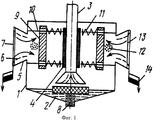
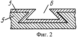
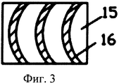
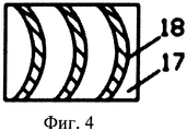
На фиг.1 изображена принципиальная схема фильтра для очистки воздуха, на фиг.2 - профиль криволинейных канавок в виде ласточкина хвоста, на фиг.3 - внешняя поверхность конической насадки с радиальными канавками, кривизна направляющей которых направлена по движению часовой стрелки, на фиг.4 - внутренняя поверхность конического днища с винтовыми канавками, кривизна направляющей которых направлена против движения часовой стрелки.Figure 1 shows a schematic diagram of a filter for air purification, figure 2 - profile of curved grooves in the form of a dovetail, figure 3 - the outer surface of the conical nozzle with radial grooves, the curvature of the guide which is directed clockwise, in fig. 4 - the inner surface of the conical bottom with helical grooves, the curvature of the guide which is directed counterclockwise.
Фильтр для очистки воздуха состоит из корпуса 1 с коническим днищем 2, выполненным с отверстием в нижней части, штуцера вывода очищенного воздуха 3, обтянутого проволочной сеткой 4 и имеющего коническую насадку с радиальными канавками на внешней поверхности, штуцеров ввода очищаемого воздуха в виде суживающихся дозвуковых сопел 5 с криволинейными канавками 6 на внутренней поверхности и имеющих со стороны входа атмосферного воздуха металлические сетки 7, расположенного в отверстии днища корпуса 1 конденсатоотводчика 8, отражательной перегородки 9, свободно установленной на направляющих стержнях 10 и фиксируемой пружинами 11, и образует полость 12, заключенную между выходным сечением суживающегося дозвукового сопла 5 и отражательной перегородкой 9, при этом на внутренней поверхности суживающихся дозвуковых сопел 5 выполнена кольцевая канавка для удаления загрязнений 14, расположенная за металлической сеткой 7 и соединенная с криволинейными канавками 6. На внешней поверхности 15 конической насадки штуцера вывода очищенного воздуха 3 выполнены радиальные канавки 16, кривизна направляющей которых направлена по движению часовой стрелки, и на внутренней поверхности 17 конического днища 2 выполнены винтовые канавки 18, кривизна направляющей которых направлена против движения часовой стрелки.The air purification filter consists of a
Фильтр работает следующим образом.The filter works as follows.
По мере накопления в коническом днище 2 каплеобразной жидкости поверхность зеркала ее увеличивается с образованием выталкивающей силы на конденсатоотводчик 8. Очищаемый атмосферный всасываемый воздух, огибая отражательную перегородку 9, проходит под поверхностью конденсата, накапливаемого в коническом днище 2, далее перемещается по радиальным канавкам 16, находящимся на внешней поверхности 15 штуцера вывода очищаемого воздуха 3, и, проходя через проволочную сетку 4, поступает очищенным в компрессор (не показано).As a droplet-like liquid accumulates in the conical bottom 2, its mirror surface increases with the formation of a buoyant force on the
На внешней поверхности 15 конической насадки штуцера ввода очищенного воздуха 3 выполнены радиальные канавки 16, кривизна направляющей которых направлена по движению часовой стрелки, а на внутренней поверхности 17 конического днища 2 выполнены винтовые канавки 18, кривизна направляющих которых направлена против движения часовой стрелки. В этом случае, при накоплении конденсата в коническом днище 2 до уровня открытия конденсатоотводчиком 8 отверстия в нижней части, наблюдается перемещение жидкости, контактирующей с внешней поверхностью 15, и она же перемещается по винтовым канавкам, закручивается, образуя еще на выходе из кольцевой щели и далее, выходя из отверстия, открытого конденсатоотводчиком 8 в коническом днище 2, воронку с повышенной скоростью истечения, что ускоряет время полного открытия отверстия в коническом днище 2. Выполнение радиальных канавок 16 на внешней поверхности 15 штуцера вывода очищаемого воздуха 3 конического днища 2 приводит к вращению потока жидкости в процессе истечения по направлению движения часовой стрелки. Кроме того, очищаемый атмосферный всасываемый воздух, перемещаясь по направлению движения часовой стрелки, образует на поверхности зеркала конденсата конического днища 2 микроворонку, вращающуюся в данном направлении. В результате на поверхности объема жидкости образуются встречно движущиеся микрозавихрения, которые, сталкиваясь, приводят к микровзрывам, воздействующим на поверхность конденсатоотводчика 8, выступающую под зеркалом с конденсирующейся жидкостью в коническом днище 2. Дополнительное воздействие на данную поверхность конденсатоотводчика практически устраняет его инерционность в процессе закрытия отверстия в коническом днище 2 при окончании сброса конденсата в окружающую среду из корпуса 1 фильтра (см., например, Меркулов П.И. Вихревой эффект и его применение в промышленности. Куйбышев, 1996. - 363 с.).On the
В результате удаление избытка сконденсировавшейся жидкости из конического днища 2 через отверстие в нижней части осуществляется без дополнительного расхода атмосферного воздуха, который после соответствующей обработки в качестве всасываемого в полном объеме в режиме резонансного наддува поступает в компрессор следующим образом.As a result, the removal of excess condensed liquid from the conical bottom 2 through the hole in the lower part is carried out without additional consumption of atmospheric air, which, after appropriate treatment, is fully absorbed in the resonant pressurization mode and enters the compressor as follows.
Атмосферный воздух определенной плотности, характеризуемой наряду с давлением, его температурой, загрязнениями в виде твердых частиц пыли каплеобразной влаги, концентрация которых зависит как от климатических, так и технологических условий эксплуатации компрессорной установки, т.е. нахождением в промышленной зоне, обусловленной количеством технологических выбросов, поступает в качестве многокомпонентной смеси в суживающиеся дозвуковые сопла 5 и по мере возрастания скорости всасываемого потока, оттесняются к стенке и попадают в полости криволинейных канавок 6, где, сталкиваясь с другими частицами, укрупняются и становятся «ядрами» конденсации водяного пара. Закручивание в криволинейных канавках более плотного потока пограничного слоя приводит к вращательному движению всего потока всасываемого воздуха перед выходным отверстием суживающегося дозвукового сопла 5, что приводит к более интенсивной коагуляции легких мелких частиц и в конечном счете улучшает работу фильтра. Это вызывает дополнительную коагуляцию мельчайших частиц влаги, которые с твердыми частицами пыли, а при отрицательных температурах и с твердой фазой жидкости поступают в полость 12 и ударяются об отражательную перегородку 9, подаются на коническое днище 2, где скапливается конденсат. В результате этого осуществляется смачивание упавших частиц. Тем самым предотвращается их унос к проволочной сетке 4.Atmospheric air of a certain density, characterized along with pressure, its temperature, pollution in the form of solid particles of dust, droplet-like moisture, the concentration of which depends on both climatic and technological operating conditions of the compressor unit, i.e. being in the industrial zone, due to the amount of technological emissions, enters as a multicomponent mixture in the narrowing
Полость 12 представляет собой объем, заключенный между выходным сечением суживающегося дозвукового сопла 5 и отражательной перегородкой 9. При этом размер выбран так, что он соответствует объему резонатора. В связи с тем, что плотность воздуха, поступающего в полость 12, изменяется в зависимости от погодно-климатических и технологических условий эксплуатации компрессорной станции, резонатор должен иметь переменный объем. За начальное положение объема резонатора принимаются размеры полости 12 воздушного фильтра компрессора, образованного выходным сечением суживающегося дозвукового сопла 5 и отражательной перегородки 9, которая фиксируется пружинами 1 в свободном состоянии на направляющих стержнях 10. В этом случае воздействие, оказываемое атмосферным всасываемым воздухом, определяется наименьшей плотностью, соответствующей максимальной температуре окружающей среды (известно, что чем выше температура воздуха, тем ниже его плотность), минимальному количеству загрязнений, поступающих в воздушный фильтр компрессора. Все это определяется экспериментальным путем согласно условиям эксплуатации компрессорной станции.The
По мере снижения температуры атмосферного воздуха или увеличения количества загрязнений в нем плотность всасываемого воздуха увеличивается, в результате энергия удара потока смеси (атмосферного воздуха и загрязнений в нем) об отражательную перегородку 9 увеличивается и последняя перемещается по направляющим стержням 10, сжимая пружину 11. При перемещении отражательной перегородки 9 объем воздушного столба в полости 12 увеличивается, сохраняя постоянство резонатора при изменяющихся погодно-климатических и технологических загрязнениях в нормированных пределах. В случае последующего уменьшения плотности потока всасываемого воздуха (увеличилась температура атмосферного воздуха или уменьшилось количество загрязнений в нем) отражательная перегородка 9 под действием разжимающего усилия пружины 11 перемещается в сторону выходного сечения суживающегося дозвукового сопла 5, что уменьшает объем воздушного столба в полости 12. В результате наблюдается пульсирующее перемещение отражательной перегородки 9 на направляющих стержнях 10 под действием пружины 11, что обеспечивает постоянство объема резонатора и соответственно влияет на оптимальное воздействие резонансного наддува на величину наполнения цилиндра компрессора.As the temperature of atmospheric air decreases or the amount of pollution in it increases, the density of the intake air increases, as a result, the impact energy of the mixture flow (atmospheric air and pollution in it) against the reflective wall 9 increases and the latter moves along the guide rods 10, compressing the
Выполнение же криволинейных канавок 6 с полостью в виде ласточкина хвоста практически устраняет вероятность выпадения твердых и сконденсировавшихся каплеобразных частиц, и они перемещаются к концевой канавке 13, откуда по мере накопления удаляются вручную или автоматически через устройство удаления 14. В этом случае в движущемся по суживающимся дозвуковым соплам 5 потоке всасываемого атмосферного воздуха находится то нормированное количество загрязнений, в допустимых пределах которого построен резонатор, включающий полость 12 и подпружиненную отражательную перегородку 9. В результате осуществляется эффективная работа фильтра со снижением энергоемкости производства сжатого воздуха.The execution of
Температура периферийных «горячих» слоев закрученного движущегося потока всасываемого атмосферного воздуха внутри суживающегося дозвукового сопла 5 превышает температуру воздуха, окружающего компрессорную установку среды. Поэтому корпус суживающегося дозвукового сопла 5, выполненный из биметалла, постоянно в процессе производства сжатого воздуха находится под действием температурного напора, приводящего к возникновению в биметаллической конструкции корпусов суживающихся дозвуковых сопел 5 продольных колебаний термовибраций.The temperature of the peripheral "hot" layers of the swirling moving flow of intake atmospheric air inside the tapering
В результате наблюдается разрушение образующихся «пробок» (сталкивающиеся твердые и каплеобразные частицы иногда сливаются - сливаются в частицы, соизмеримые с размерами полости внутриобразных канавок, что может приводить к закупориванию элемента полости, т.е. образованию «пробки» в полостях с профилем в виде ласточкина хвоста криволинейных канавок, и осуществляется бесперебойное поступление отделенных от движущегося всасываемого атмосферного воздуха загрязнений в концевую канавку 13, находящуюся у металлической сетки 7 суживающихся дозвуковых сопел 5.As a result, destruction of the resulting “plugs” is observed (colliding solid and droplet-like particles sometimes merge - merge into particles that are comparable to the dimensions of the cavity of the intra-shaped grooves, which can lead to clogging of the cavity element, i.e., the formation of a “plug” in cavities with a profile in the form dovetail of the curved grooves, and there is an uninterrupted flow of contaminants separated from the moving intake air into the
Под совместным действием гравитационных сил и термовибрации корпуса суживающихся дозвуковых сопел 5 загрязнения поступают в устройство для удаления загрязнений 14, из которого удаляется вручную или автоматически.Under the combined action of gravitational forces and thermal vibration, the bodies of the tapering
Оригинальность предлагаемого технического решения состоит в том, что обеспечивается снижение энергоемкости производства сжатого воздуха, особенно в условиях эксплуатации, когда наблюдается повышенное содержание в атмосферном всасываемом воздухе каплеобразных атмосферных и технологических загрязнений, что приводит к более частому сбрасыванию конденсата через отверстие в коническом днище корпуса фильтра. Закручивание жидкости в коническом днище перед отверстием увеличивает скорость, т.е. массовый расход при сбросе конденсата, а закручивание всасываемого воздуха при перемещении его по внутренней поверхности конической насадки штуцера вывода очищенного воздуха создает микрозавихрения, имеющие обратное направление с микрозавихрениями, возникающими на поверхности зеркала конденсата, скапливаемого в коническом днище. Возникающие микровзрывы при контакте противоположно вращающихся микрозавихрений создают суммарное силовое воздействие на поверхность конденсатоотводчика, принуждая его к более быстрому закрытию отверстия в коническом днище, после выпуска жидкости.The originality of the proposed technical solution consists in the fact that the energy consumption of compressed air production is reduced, especially in operating conditions, when there is an increased content of droplet-like atmospheric and technological pollution in the atmospheric intake air, which leads to a more frequent discharge of condensate through an opening in the conical bottom of the filter housing. Twisting the liquid in the conical bottom in front of the hole increases the speed, i.e. mass flow when the condensate is discharged, and the swirling of the intake air when moving it along the inner surface of the conical nozzle of the cleaned air outlet creates micro turbulence having the opposite direction with micro turbulence occurring on the surface of the condensate mirror accumulated in the conical bottom. The resulting microexplosions upon the contact of oppositely rotating microswirls create a total force impact on the surface of the steam trap, forcing it to more quickly close the hole in the conical bottom after the liquid is discharged.
Claims (1)
Priority Applications (1)
| Application Number | Priority Date | Filing Date | Title |
|---|---|---|---|
| RU2008101583/15A RU2367503C1 (en) | 2008-01-15 | 2008-01-15 | Air cleaner |
Applications Claiming Priority (1)
| Application Number | Priority Date | Filing Date | Title |
|---|---|---|---|
| RU2008101583/15A RU2367503C1 (en) | 2008-01-15 | 2008-01-15 | Air cleaner |
Publications (1)
| Publication Number | Publication Date |
|---|---|
| RU2367503C1 true RU2367503C1 (en) | 2009-09-20 |
Family
ID=41167810
Family Applications (1)
| Application Number | Title | Priority Date | Filing Date |
|---|---|---|---|
| RU2008101583/15A RU2367503C1 (en) | 2008-01-15 | 2008-01-15 | Air cleaner |
Country Status (1)
| Country | Link |
|---|---|
| RU (1) | RU2367503C1 (en) |
Cited By (2)
| Publication number | Priority date | Publication date | Assignee | Title |
|---|---|---|---|---|
| RU2624701C1 (en) * | 2016-07-29 | 2017-07-05 | Федеральное государственное бюджетное образовательное учреждение высшего образования "Юго-Западный государственный университет" (ЮЗГУ) | Packed gas drying absorber |
| RU2641824C1 (en) * | 2016-10-31 | 2018-01-22 | Федеральное государственное бюджетное образовательное учреждение высшего образования "Юго-Западный государственный университет" (ЮЗГУ) | Filter for air cleaning |
Citations (4)
| Publication number | Priority date | Publication date | Assignee | Title |
|---|---|---|---|---|
| GB203946A (en) * | 1922-10-31 | 1923-09-20 | John Nelson Dundas Heenan | Improvements in and relating to apparatus for drying air and gases |
| GB1432050A (en) * | 1972-07-14 | 1976-04-14 | Bauer H | Apparatus for removing liquid from liquid/gas separator cart ridges |
| SU1546109A1 (en) * | 1986-03-24 | 1990-02-28 | Курский Политехнический Институт | Filter for cleaning air |
| RU2181616C1 (en) * | 2001-03-22 | 2002-04-27 | Курский государственный технический университет | Air filter |
-
2008
- 2008-01-15 RU RU2008101583/15A patent/RU2367503C1/en not_active IP Right Cessation
Patent Citations (4)
| Publication number | Priority date | Publication date | Assignee | Title |
|---|---|---|---|---|
| GB203946A (en) * | 1922-10-31 | 1923-09-20 | John Nelson Dundas Heenan | Improvements in and relating to apparatus for drying air and gases |
| GB1432050A (en) * | 1972-07-14 | 1976-04-14 | Bauer H | Apparatus for removing liquid from liquid/gas separator cart ridges |
| SU1546109A1 (en) * | 1986-03-24 | 1990-02-28 | Курский Политехнический Институт | Filter for cleaning air |
| RU2181616C1 (en) * | 2001-03-22 | 2002-04-27 | Курский государственный технический университет | Air filter |
Cited By (2)
| Publication number | Priority date | Publication date | Assignee | Title |
|---|---|---|---|---|
| RU2624701C1 (en) * | 2016-07-29 | 2017-07-05 | Федеральное государственное бюджетное образовательное учреждение высшего образования "Юго-Западный государственный университет" (ЮЗГУ) | Packed gas drying absorber |
| RU2641824C1 (en) * | 2016-10-31 | 2018-01-22 | Федеральное государственное бюджетное образовательное учреждение высшего образования "Юго-Западный государственный университет" (ЮЗГУ) | Filter for air cleaning |
Similar Documents
| Publication | Publication Date | Title |
|---|---|---|
| US4162905A (en) | Air intake filter with cyclone separator stage | |
| CN201049265Y (en) | Air filter | |
| CN211069511U (en) | Leading filtering formula wet dedusting fan | |
| SE415791B (en) | COMBINED SILENCER AND OIL OVELA for compressed air appliances | |
| RU2367503C1 (en) | Air cleaner | |
| RU2181616C1 (en) | Air filter | |
| CN109011984A (en) | A kind of high-efficiency cyclone coalescence dedusting demister | |
| RU138469U1 (en) | FILTER FOR CLEANING THE AIR | |
| RU2641824C1 (en) | Filter for air cleaning | |
| KR20160109553A (en) | Complex multi-cyclone dust collector | |
| US20050172583A1 (en) | Demisting chamber with elbow strainer | |
| RU158010U1 (en) | FILTER FOR CLEANING THE AIR | |
| CN205803983U (en) | Fiber remover | |
| RU2174452C1 (en) | Dust collector | |
| KR101213150B1 (en) | Apparatus for removing moisture | |
| FR2518894A1 (en) | Centrifugal air filter - removes coarse dust particles using helicoidal air motion induced by axial flow fan impeller | |
| KR100780839B1 (en) | Compressor Filter | |
| RU2050945C1 (en) | Filter for cleaning air | |
| CN208824156U (en) | A wet dust collector with high frequency vibration of filter screen | |
| RU2291737C2 (en) | Air purification filter | |
| SU1457968A1 (en) | Apparatus for cleaning gases from dust | |
| RU2190077C2 (en) | Gear for flame and mechanical drilling of holes | |
| CN107051013A (en) | Screw type air purifier | |
| RU95105811A (en) | Air-cleaning filter | |
| CN119236585B (en) | Leaching filter bag dust removal device |
Legal Events
| Date | Code | Title | Description |
|---|---|---|---|
| MM4A | The patent is invalid due to non-payment of fees |
Effective date: 20100116 |