RU2362239C2 - Method of making solid-oxide fuel cell - Google Patents
Method of making solid-oxide fuel cell Download PDFInfo
- Publication number
- RU2362239C2 RU2362239C2 RU2006110158/09A RU2006110158A RU2362239C2 RU 2362239 C2 RU2362239 C2 RU 2362239C2 RU 2006110158/09 A RU2006110158/09 A RU 2006110158/09A RU 2006110158 A RU2006110158 A RU 2006110158A RU 2362239 C2 RU2362239 C2 RU 2362239C2
- Authority
- RU
- Russia
- Prior art keywords
- layer
- electrode
- electrolyte
- thickness
- fuel cell
- Prior art date
Links
- 239000000446 fuel Substances 0.000 title claims abstract description 61
- 238000004519 manufacturing process Methods 0.000 title claims abstract description 27
- 238000000034 method Methods 0.000 claims abstract description 75
- 239000003792 electrolyte Substances 0.000 claims abstract description 64
- 238000010438 heat treatment Methods 0.000 claims abstract description 23
- 239000002001 electrolyte material Substances 0.000 claims abstract description 15
- 230000015572 biosynthetic process Effects 0.000 claims abstract description 12
- 239000000126 substance Substances 0.000 claims abstract description 5
- 230000005855 radiation Effects 0.000 claims abstract description 4
- 230000008021 deposition Effects 0.000 claims abstract 6
- 239000007787 solid Substances 0.000 claims description 29
- 239000002131 composite material Substances 0.000 claims description 23
- 239000000463 material Substances 0.000 claims description 22
- 239000011230 binding agent Substances 0.000 claims description 18
- 238000001354 calcination Methods 0.000 claims description 18
- 238000001035 drying Methods 0.000 claims description 13
- 239000002270 dispersing agent Substances 0.000 claims description 12
- 239000000725 suspension Substances 0.000 claims description 12
- 239000002904 solvent Substances 0.000 claims description 11
- 239000004014 plasticizer Substances 0.000 claims description 10
- 239000000919 ceramic Substances 0.000 claims description 9
- 230000005611 electricity Effects 0.000 claims description 8
- 238000007650 screen-printing Methods 0.000 claims description 8
- 229910000420 cerium oxide Inorganic materials 0.000 claims description 6
- 239000004020 conductor Substances 0.000 claims description 6
- BMMGVYCKOGBVEV-UHFFFAOYSA-N oxo(oxoceriooxy)cerium Chemical compound [Ce]=O.O=[Ce]=O BMMGVYCKOGBVEV-UHFFFAOYSA-N 0.000 claims description 6
- 229910052727 yttrium Inorganic materials 0.000 claims description 6
- VWQVUPCCIRVNHF-UHFFFAOYSA-N yttrium atom Chemical compound [Y] VWQVUPCCIRVNHF-UHFFFAOYSA-N 0.000 claims description 6
- QCWXUUIWCKQGHC-UHFFFAOYSA-N Zirconium Chemical compound [Zr] QCWXUUIWCKQGHC-UHFFFAOYSA-N 0.000 claims description 5
- 238000005245 sintering Methods 0.000 claims description 5
- 229910052726 zirconium Inorganic materials 0.000 claims description 5
- RHLFGQZLNLRASV-UHFFFAOYSA-N [O-2].[Sm+3].[Ni+2] Chemical compound [O-2].[Sm+3].[Ni+2] RHLFGQZLNLRASV-UHFFFAOYSA-N 0.000 claims description 2
- QAISYPNSOYCTPY-UHFFFAOYSA-N cerium(3+) gadolinium(3+) oxygen(2-) Chemical compound [O--].[O--].[O--].[Ce+3].[Gd+3] QAISYPNSOYCTPY-UHFFFAOYSA-N 0.000 claims description 2
- HZLLPQBYQASDPK-UHFFFAOYSA-N gadolinium(3+) nickel(2+) oxygen(2-) Chemical compound [O-2].[Gd+3].[Ni+2] HZLLPQBYQASDPK-UHFFFAOYSA-N 0.000 claims description 2
- RIAXXCZORHQTQD-UHFFFAOYSA-N lanthanum magnesium Chemical compound [Mg].[La] RIAXXCZORHQTQD-UHFFFAOYSA-N 0.000 claims description 2
- 229910052761 rare earth metal Inorganic materials 0.000 claims description 2
- 150000002910 rare earth metals Chemical class 0.000 claims description 2
- 239000007784 solid electrolyte Substances 0.000 claims description 2
- 239000004449 solid propellant Substances 0.000 claims description 2
- 229910052712 strontium Inorganic materials 0.000 claims description 2
- CIOAGBVUUVVLOB-UHFFFAOYSA-N strontium atom Chemical compound [Sr] CIOAGBVUUVVLOB-UHFFFAOYSA-N 0.000 claims description 2
- 239000011262 electrochemically active material Substances 0.000 claims 4
- MCMNRKCIXSYSNV-UHFFFAOYSA-N Zirconium dioxide Chemical compound O=[Zr]=O MCMNRKCIXSYSNV-UHFFFAOYSA-N 0.000 claims 2
- 238000005259 measurement Methods 0.000 claims 2
- 229910052684 Cerium Inorganic materials 0.000 claims 1
- GWXLDORMOJMVQZ-UHFFFAOYSA-N cerium Chemical compound [Ce] GWXLDORMOJMVQZ-UHFFFAOYSA-N 0.000 claims 1
- VAUNMJNZQZLHJE-UHFFFAOYSA-N cobalt gadolinium Chemical compound [Co].[Gd] VAUNMJNZQZLHJE-UHFFFAOYSA-N 0.000 claims 1
- VQVNCTNULYBZGL-UHFFFAOYSA-N cobalt yttrium Chemical compound [Co].[Y] VQVNCTNULYBZGL-UHFFFAOYSA-N 0.000 claims 1
- 229910021526 gadolinium-doped ceria Inorganic materials 0.000 claims 1
- IKBUJAGPKSFLPB-UHFFFAOYSA-N nickel yttrium Chemical compound [Ni].[Y] IKBUJAGPKSFLPB-UHFFFAOYSA-N 0.000 claims 1
- RVTZCBVAJQQJTK-UHFFFAOYSA-N oxygen(2-);zirconium(4+) Chemical compound [O-2].[O-2].[Zr+4] RVTZCBVAJQQJTK-UHFFFAOYSA-N 0.000 claims 1
- 238000004062 sedimentation Methods 0.000 claims 1
- PDGYMUBNWUUWEI-UHFFFAOYSA-N strontium zirconium Chemical compound [Sr].[Zr] PDGYMUBNWUUWEI-UHFFFAOYSA-N 0.000 claims 1
- 229910001928 zirconium oxide Inorganic materials 0.000 claims 1
- 238000000151 deposition Methods 0.000 abstract description 5
- 238000005054 agglomeration Methods 0.000 abstract 2
- 230000002776 aggregation Effects 0.000 abstract 2
- 230000000694 effects Effects 0.000 abstract 1
- 239000010410 layer Substances 0.000 description 53
- 230000008569 process Effects 0.000 description 10
- 239000002245 particle Substances 0.000 description 9
- PXHVJJICTQNCMI-UHFFFAOYSA-N Nickel Chemical compound [Ni] PXHVJJICTQNCMI-UHFFFAOYSA-N 0.000 description 6
- 238000005266 casting Methods 0.000 description 6
- 238000009826 distribution Methods 0.000 description 6
- 239000007789 gas Substances 0.000 description 6
- 239000002356 single layer Substances 0.000 description 6
- BQENXCOZCUHKRE-UHFFFAOYSA-N [La+3].[La+3].[O-][Mn]([O-])=O.[O-][Mn]([O-])=O.[O-][Mn]([O-])=O Chemical compound [La+3].[La+3].[O-][Mn]([O-])=O.[O-][Mn]([O-])=O.[O-][Mn]([O-])=O BQENXCOZCUHKRE-UHFFFAOYSA-N 0.000 description 5
- 229910000480 nickel oxide Inorganic materials 0.000 description 5
- GNRSAWUEBMWBQH-UHFFFAOYSA-N oxonickel Chemical compound [Ni]=O GNRSAWUEBMWBQH-UHFFFAOYSA-N 0.000 description 5
- 238000007639 printing Methods 0.000 description 5
- QVGXLLKOCUKJST-UHFFFAOYSA-N atomic oxygen Chemical compound [O] QVGXLLKOCUKJST-UHFFFAOYSA-N 0.000 description 4
- 150000001875 compounds Chemical class 0.000 description 4
- 238000003487 electrochemical reaction Methods 0.000 description 4
- 239000001301 oxygen Substances 0.000 description 4
- 229910052760 oxygen Inorganic materials 0.000 description 4
- LFQSCWFLJHTTHZ-UHFFFAOYSA-N Ethanol Chemical compound CCO LFQSCWFLJHTTHZ-UHFFFAOYSA-N 0.000 description 3
- UFHFLCQGNIYNRP-UHFFFAOYSA-N Hydrogen Chemical compound [H][H] UFHFLCQGNIYNRP-UHFFFAOYSA-N 0.000 description 3
- OKKJLVBELUTLKV-UHFFFAOYSA-N Methanol Chemical compound OC OKKJLVBELUTLKV-UHFFFAOYSA-N 0.000 description 3
- YXFVVABEGXRONW-UHFFFAOYSA-N Toluene Chemical compound CC1=CC=CC=C1 YXFVVABEGXRONW-UHFFFAOYSA-N 0.000 description 3
- 239000003054 catalyst Substances 0.000 description 3
- 230000001413 cellular effect Effects 0.000 description 3
- 238000010586 diagram Methods 0.000 description 3
- 239000001257 hydrogen Substances 0.000 description 3
- 229910052739 hydrogen Inorganic materials 0.000 description 3
- 239000010416 ion conductor Substances 0.000 description 3
- 229910052759 nickel Inorganic materials 0.000 description 3
- 230000000737 periodic effect Effects 0.000 description 3
- 239000000758 substrate Substances 0.000 description 3
- KFZMGEQAYNKOFK-UHFFFAOYSA-N Isopropanol Chemical compound CC(C)O KFZMGEQAYNKOFK-UHFFFAOYSA-N 0.000 description 2
- ZOKXTWBITQBERF-UHFFFAOYSA-N Molybdenum Chemical compound [Mo] ZOKXTWBITQBERF-UHFFFAOYSA-N 0.000 description 2
- NBIIXXVUZAFLBC-UHFFFAOYSA-N Phosphoric acid Chemical compound OP(O)(O)=O NBIIXXVUZAFLBC-UHFFFAOYSA-N 0.000 description 2
- -1 alkali metal salts Chemical class 0.000 description 2
- 239000012298 atmosphere Substances 0.000 description 2
- 230000008859 change Effects 0.000 description 2
- 239000002803 fossil fuel Substances 0.000 description 2
- 229910052750 molybdenum Inorganic materials 0.000 description 2
- 239000011733 molybdenum Substances 0.000 description 2
- 239000011185 multilayer composite material Substances 0.000 description 2
- 238000012545 processing Methods 0.000 description 2
- XLYOFNOQVPJJNP-UHFFFAOYSA-N water Substances O XLYOFNOQVPJJNP-UHFFFAOYSA-N 0.000 description 2
- OKTJSMMVPCPJKN-UHFFFAOYSA-N Carbon Chemical group [C] OKTJSMMVPCPJKN-UHFFFAOYSA-N 0.000 description 1
- BVKZGUZCCUSVTD-UHFFFAOYSA-L Carbonate Chemical compound [O-]C([O-])=O BVKZGUZCCUSVTD-UHFFFAOYSA-L 0.000 description 1
- 229910018487 Ni—Cr Inorganic materials 0.000 description 1
- BPQQTUXANYXVAA-UHFFFAOYSA-N Orthosilicate Chemical compound [O-][Si]([O-])([O-])[O-] BPQQTUXANYXVAA-UHFFFAOYSA-N 0.000 description 1
- 239000004372 Polyvinyl alcohol Substances 0.000 description 1
- 229910052783 alkali metal Inorganic materials 0.000 description 1
- 229910000147 aluminium phosphate Inorganic materials 0.000 description 1
- 238000010923 batch production Methods 0.000 description 1
- 238000006243 chemical reaction Methods 0.000 description 1
- 239000003795 chemical substances by application Substances 0.000 description 1
- VNNRSPGTAMTISX-UHFFFAOYSA-N chromium nickel Chemical compound [Cr].[Ni] VNNRSPGTAMTISX-UHFFFAOYSA-N 0.000 description 1
- NFYLSJDPENHSBT-UHFFFAOYSA-N chromium(3+);lanthanum(3+);oxygen(2-) Chemical compound [O-2].[O-2].[O-2].[Cr+3].[La+3] NFYLSJDPENHSBT-UHFFFAOYSA-N 0.000 description 1
- 238000010344 co-firing Methods 0.000 description 1
- 229910017052 cobalt Inorganic materials 0.000 description 1
- 239000010941 cobalt Substances 0.000 description 1
- GUTLYIVDDKVIGB-UHFFFAOYSA-N cobalt atom Chemical compound [Co] GUTLYIVDDKVIGB-UHFFFAOYSA-N 0.000 description 1
- ZXIMJENGZNNPHH-UHFFFAOYSA-N cobalt(2+) gadolinium(3+) oxygen(2-) Chemical compound [O-2].[Gd+3].[Co+2] ZXIMJENGZNNPHH-UHFFFAOYSA-N 0.000 description 1
- 238000010924 continuous production Methods 0.000 description 1
- 239000007822 coupling agent Substances 0.000 description 1
- 230000006378 damage Effects 0.000 description 1
- 238000001652 electrophoretic deposition Methods 0.000 description 1
- 238000010304 firing Methods 0.000 description 1
- 235000021323 fish oil Nutrition 0.000 description 1
- 238000005470 impregnation Methods 0.000 description 1
- 238000007641 inkjet printing Methods 0.000 description 1
- 239000000155 melt Substances 0.000 description 1
- 239000012528 membrane Substances 0.000 description 1
- 239000000203 mixture Substances 0.000 description 1
- 230000004048 modification Effects 0.000 description 1
- 238000012986 modification Methods 0.000 description 1
- 230000003287 optical effect Effects 0.000 description 1
- 239000007800 oxidant agent Substances 0.000 description 1
- 230000001590 oxidative effect Effects 0.000 description 1
- 229920002037 poly(vinyl butyral) polymer Polymers 0.000 description 1
- 229920002451 polyvinyl alcohol Polymers 0.000 description 1
- 238000003825 pressing Methods 0.000 description 1
- HBMJWWWQQXIZIP-UHFFFAOYSA-N silicon carbide Chemical compound [Si+]#[C-] HBMJWWWQQXIZIP-UHFFFAOYSA-N 0.000 description 1
- 229910010271 silicon carbide Inorganic materials 0.000 description 1
- 239000002002 slurry Substances 0.000 description 1
- 238000001228 spectrum Methods 0.000 description 1
- 238000005507 spraying Methods 0.000 description 1
- 238000010561 standard procedure Methods 0.000 description 1
- 238000012546 transfer Methods 0.000 description 1
Images
Classifications
-
- H—ELECTRICITY
- H01—ELECTRIC ELEMENTS
- H01M—PROCESSES OR MEANS, e.g. BATTERIES, FOR THE DIRECT CONVERSION OF CHEMICAL ENERGY INTO ELECTRICAL ENERGY
- H01M8/00—Fuel cells; Manufacture thereof
-
- H—ELECTRICITY
- H01—ELECTRIC ELEMENTS
- H01M—PROCESSES OR MEANS, e.g. BATTERIES, FOR THE DIRECT CONVERSION OF CHEMICAL ENERGY INTO ELECTRICAL ENERGY
- H01M4/00—Electrodes
- H01M4/86—Inert electrodes with catalytic activity, e.g. for fuel cells
- H01M4/90—Selection of catalytic material
- H01M4/9016—Oxides, hydroxides or oxygenated metallic salts
- H01M4/9025—Oxides specially used in fuel cell operating at high temperature, e.g. SOFC
- H01M4/9033—Complex oxides, optionally doped, of the type M1MeO3, M1 being an alkaline earth metal or a rare earth, Me being a metal, e.g. perovskites
-
- H—ELECTRICITY
- H01—ELECTRIC ELEMENTS
- H01M—PROCESSES OR MEANS, e.g. BATTERIES, FOR THE DIRECT CONVERSION OF CHEMICAL ENERGY INTO ELECTRICAL ENERGY
- H01M4/00—Electrodes
- H01M4/86—Inert electrodes with catalytic activity, e.g. for fuel cells
-
- H—ELECTRICITY
- H01—ELECTRIC ELEMENTS
- H01M—PROCESSES OR MEANS, e.g. BATTERIES, FOR THE DIRECT CONVERSION OF CHEMICAL ENERGY INTO ELECTRICAL ENERGY
- H01M4/00—Electrodes
- H01M4/86—Inert electrodes with catalytic activity, e.g. for fuel cells
- H01M4/8605—Porous electrodes
- H01M4/8621—Porous electrodes containing only metallic or ceramic material, e.g. made by sintering or sputtering
-
- H—ELECTRICITY
- H01—ELECTRIC ELEMENTS
- H01M—PROCESSES OR MEANS, e.g. BATTERIES, FOR THE DIRECT CONVERSION OF CHEMICAL ENERGY INTO ELECTRICAL ENERGY
- H01M4/00—Electrodes
- H01M4/86—Inert electrodes with catalytic activity, e.g. for fuel cells
- H01M4/8647—Inert electrodes with catalytic activity, e.g. for fuel cells consisting of more than one material, e.g. consisting of composites
- H01M4/8657—Inert electrodes with catalytic activity, e.g. for fuel cells consisting of more than one material, e.g. consisting of composites layered
-
- H—ELECTRICITY
- H01—ELECTRIC ELEMENTS
- H01M—PROCESSES OR MEANS, e.g. BATTERIES, FOR THE DIRECT CONVERSION OF CHEMICAL ENERGY INTO ELECTRICAL ENERGY
- H01M4/00—Electrodes
- H01M4/86—Inert electrodes with catalytic activity, e.g. for fuel cells
- H01M4/88—Processes of manufacture
- H01M4/8878—Treatment steps after deposition of the catalytic active composition or after shaping of the electrode being free-standing body
- H01M4/8882—Heat treatment, e.g. drying, baking
- H01M4/8885—Sintering or firing
-
- H—ELECTRICITY
- H01—ELECTRIC ELEMENTS
- H01M—PROCESSES OR MEANS, e.g. BATTERIES, FOR THE DIRECT CONVERSION OF CHEMICAL ENERGY INTO ELECTRICAL ENERGY
- H01M4/00—Electrodes
- H01M4/86—Inert electrodes with catalytic activity, e.g. for fuel cells
- H01M4/90—Selection of catalytic material
- H01M4/9016—Oxides, hydroxides or oxygenated metallic salts
-
- H—ELECTRICITY
- H01—ELECTRIC ELEMENTS
- H01M—PROCESSES OR MEANS, e.g. BATTERIES, FOR THE DIRECT CONVERSION OF CHEMICAL ENERGY INTO ELECTRICAL ENERGY
- H01M4/00—Electrodes
- H01M4/86—Inert electrodes with catalytic activity, e.g. for fuel cells
- H01M4/90—Selection of catalytic material
- H01M4/9041—Metals or alloys
- H01M4/905—Metals or alloys specially used in fuel cell operating at high temperature, e.g. SOFC
- H01M4/9066—Metals or alloys specially used in fuel cell operating at high temperature, e.g. SOFC of metal-ceramic composites or mixtures, e.g. cermets
-
- H—ELECTRICITY
- H01—ELECTRIC ELEMENTS
- H01M—PROCESSES OR MEANS, e.g. BATTERIES, FOR THE DIRECT CONVERSION OF CHEMICAL ENERGY INTO ELECTRICAL ENERGY
- H01M8/00—Fuel cells; Manufacture thereof
- H01M8/10—Fuel cells with solid electrolytes
- H01M8/12—Fuel cells with solid electrolytes operating at high temperature, e.g. with stabilised ZrO2 electrolyte
- H01M8/1213—Fuel cells with solid electrolytes operating at high temperature, e.g. with stabilised ZrO2 electrolyte characterised by the electrode/electrolyte combination or the supporting material
-
- H—ELECTRICITY
- H01—ELECTRIC ELEMENTS
- H01M—PROCESSES OR MEANS, e.g. BATTERIES, FOR THE DIRECT CONVERSION OF CHEMICAL ENERGY INTO ELECTRICAL ENERGY
- H01M8/00—Fuel cells; Manufacture thereof
- H01M8/10—Fuel cells with solid electrolytes
- H01M8/12—Fuel cells with solid electrolytes operating at high temperature, e.g. with stabilised ZrO2 electrolyte
- H01M8/124—Fuel cells with solid electrolytes operating at high temperature, e.g. with stabilised ZrO2 electrolyte characterised by the process of manufacturing or by the material of the electrolyte
- H01M8/1246—Fuel cells with solid electrolytes operating at high temperature, e.g. with stabilised ZrO2 electrolyte characterised by the process of manufacturing or by the material of the electrolyte the electrolyte consisting of oxides
-
- H—ELECTRICITY
- H01—ELECTRIC ELEMENTS
- H01M—PROCESSES OR MEANS, e.g. BATTERIES, FOR THE DIRECT CONVERSION OF CHEMICAL ENERGY INTO ELECTRICAL ENERGY
- H01M2300/00—Electrolytes
- H01M2300/0017—Non-aqueous electrolytes
- H01M2300/0065—Solid electrolytes
- H01M2300/0068—Solid electrolytes inorganic
- H01M2300/0071—Oxides
- H01M2300/0074—Ion conductive at high temperature
- H01M2300/0077—Ion conductive at high temperature based on zirconium oxide
-
- H—ELECTRICITY
- H01—ELECTRIC ELEMENTS
- H01M—PROCESSES OR MEANS, e.g. BATTERIES, FOR THE DIRECT CONVERSION OF CHEMICAL ENERGY INTO ELECTRICAL ENERGY
- H01M2300/00—Electrolytes
- H01M2300/0088—Composites
- H01M2300/0094—Composites in the form of layered products, e.g. coatings
-
- Y—GENERAL TAGGING OF NEW TECHNOLOGICAL DEVELOPMENTS; GENERAL TAGGING OF CROSS-SECTIONAL TECHNOLOGIES SPANNING OVER SEVERAL SECTIONS OF THE IPC; TECHNICAL SUBJECTS COVERED BY FORMER USPC CROSS-REFERENCE ART COLLECTIONS [XRACs] AND DIGESTS
- Y02—TECHNOLOGIES OR APPLICATIONS FOR MITIGATION OR ADAPTATION AGAINST CLIMATE CHANGE
- Y02E—REDUCTION OF GREENHOUSE GAS [GHG] EMISSIONS, RELATED TO ENERGY GENERATION, TRANSMISSION OR DISTRIBUTION
- Y02E60/00—Enabling technologies; Technologies with a potential or indirect contribution to GHG emissions mitigation
- Y02E60/30—Hydrogen technology
- Y02E60/50—Fuel cells
-
- Y—GENERAL TAGGING OF NEW TECHNOLOGICAL DEVELOPMENTS; GENERAL TAGGING OF CROSS-SECTIONAL TECHNOLOGIES SPANNING OVER SEVERAL SECTIONS OF THE IPC; TECHNICAL SUBJECTS COVERED BY FORMER USPC CROSS-REFERENCE ART COLLECTIONS [XRACs] AND DIGESTS
- Y02—TECHNOLOGIES OR APPLICATIONS FOR MITIGATION OR ADAPTATION AGAINST CLIMATE CHANGE
- Y02P—CLIMATE CHANGE MITIGATION TECHNOLOGIES IN THE PRODUCTION OR PROCESSING OF GOODS
- Y02P70/00—Climate change mitigation technologies in the production process for final industrial or consumer products
- Y02P70/50—Manufacturing or production processes characterised by the final manufactured product
Landscapes
- Chemical & Material Sciences (AREA)
- Engineering & Computer Science (AREA)
- Electrochemistry (AREA)
- General Chemical & Material Sciences (AREA)
- Chemical Kinetics & Catalysis (AREA)
- Manufacturing & Machinery (AREA)
- Materials Engineering (AREA)
- Sustainable Energy (AREA)
- Life Sciences & Earth Sciences (AREA)
- Sustainable Development (AREA)
- Composite Materials (AREA)
- Ceramic Engineering (AREA)
- Physics & Mathematics (AREA)
- Thermal Sciences (AREA)
- Inert Electrodes (AREA)
- Fuel Cell (AREA)
Abstract
Description
Перекрестная ссылка на родственные заявкиCross reference to related applications
В этой заявке заявляется приоритет предварительной заявки США за номером 60/501742, поданной 10 сентября 2003 года и озаглавленной SINGLE STEP CO-FIRING PROCESS FOR FUEL CELL MANUFACTURE, которая приводится здесь в виде ссылки.This application claims priority to provisional application US No. 60/501742, filed September 10, 2003 and entitled SINGLE STEP CO-FIRING PROCESS FOR FUEL CELL MANUFACTURE, which is incorporated herein by reference.
Предпосылки создания изобретенияBACKGROUND OF THE INVENTION
Топливный элемент представляет собой устройство или систему, которая генерирует электричество за счет электрохимической реакции, в которой происходит соединение кислорода и водорода с образованием воды. Электролит в топливном элементе переносит заряженные частицы от катода к аноду. Часто применяют катализаторы для ускорения и повышения эффективности электрохимической реакции. Устройства на основе топливных элементов представляют собой жизнеспособные источники альтернативной энергии. Эти устройства являются обычно эффективными и создают меньше загрязнения, чем традиционные источники энергии. Электричество, продуцируемое топливными элементами, можно использовать для снабжения энергией, например, воздухоплавательных систем, компьютерных устройств, самоходных систем и сотовых устройств.A fuel cell is a device or system that generates electricity through an electrochemical reaction in which oxygen and hydrogen combine to form water. The electrolyte in the fuel cell carries charged particles from the cathode to the anode. Catalysts are often used to accelerate and increase the efficiency of an electrochemical reaction. Fuel cell devices are viable alternative energy sources. These devices are usually efficient and create less pollution than traditional energy sources. Electricity produced by fuel cells can be used to supply energy to, for example, aeronautical systems, computer devices, self-propelled systems and cellular devices.
Обычно топливные элементы классифицируют по типу используемого электролита. В устройствах на основе топливных элементов присутствуют различные материалы в зависимости от применения или конкретных потребностей в электроэнергии. Ряд топливных элементов включает, например, устройства на основе использования фосфорной кислоты, протонной обменной мембраны, расплавов карбонатов, солей щелочных металлов и твердого оксида. Твердый топливный элемент на основе оксида (SOFC) обеспечивает чистоту окружающей среды и представляет собой разносторонний источник энергии, который может эффективно превращать ископаемое топливо в электричество и тепло.Typically, fuel cells are classified by the type of electrolyte used. In fuel cell devices, various materials are present depending on the application or specific energy needs. A number of fuel cells include, for example, phosphoric acid based devices, a proton exchange membrane, carbonate melts, alkali metal salts and solid oxide. Solid Oxide Solid Fuel Cell (SOFC) provides a clean environment and is a versatile energy source that can efficiently convert fossil fuels into electricity and heat.
SOFC включает плотный электролит, который помещают между пористыми электродами, а именно катодом и анодом. Плотный электролит может быть твердым кислород-ионным проводником, таким как цирконий, стабилизированный иттрием (YSZ). Кроме того, катод и анод можно изготавливать из керамических композитных материалов, таких как манганит лантана, легированный стронцием-YSZ, и оксид никеля-YSZ соответственно. Устройства на основе SOFC можно компоновать также в виде плоских блоков, в которых несколько топливных элементов монтируют с внутренними соединителями, отделяющими каждый элемент.SOFC includes a dense electrolyte that is placed between the porous electrodes, namely the cathode and anode. The dense electrolyte may be a solid oxygen-ionic conductor, such as yttrium stabilized zirconium (YSZ). In addition, the cathode and anode can be made of ceramic composite materials, such as strontium-YSZ doped lanthanum manganite and YSZ nickel oxide, respectively. SOFC-based devices can also be assembled in the form of flat blocks in which several fuel cells are mounted with internal connectors that separate each element.
Препятствие для осуществления промышленного внедрения устройств на основе SOFC заключается в значительной стоимости, связанной с их изготовлением. Эта стоимость по величине на порядок выше, чем изготовление сопоставимой газовой турбины. Одной из причин такого несоответствия является то, что устройства на основе SOFC изготавливают, используя периодические процессы. Периодические процессы изготовления применяют для медленного нагревания и прокаливания структуры топливного элемента с тем, чтобы предохранять электролит и электроды от деформирования. При стандартном периодическом процессе изготовления можно равномерно нагревать и прокаливать SOFC при скорости изменения температуры около 1°С в минуту. При этой скорости может потребоваться несколько часов для спекания структур электролита и электрода. При проведении процесса может потребоваться также большое количество термических циклов для нагревания и охлаждения топливного элемента во время изготовления. Однако изготовление топливного элемента с помощью таких процессов является полностью неэффективным и дорогим. С ростом потребностей на топливные элементы существует конкретная необходимость в эффективном процессе изготовления, который является недорогим и для которого не требуется большого количества термических циклов.An obstacle to the industrial implementation of SOFC-based devices is the significant cost associated with their manufacture. This cost is an order of magnitude higher than the manufacture of a comparable gas turbine. One reason for this discrepancy is that SOFC-based devices are manufactured using batch processes. Periodic manufacturing processes are used to slowly heat and calcine the structure of the fuel cell in order to protect the electrolyte and electrodes from deformation. In a standard batch manufacturing process, SOFC can be uniformly heated and calcined at a rate of temperature change of about 1 ° C. per minute. At this speed, it may take several hours to sinter the electrolyte and electrode structures. During the process, a large number of thermal cycles may also be required to heat and cool the fuel cell during manufacture. However, fabricating a fuel cell using such processes is completely inefficient and expensive. With the growing demand for fuel cells, there is a particular need for an efficient manufacturing process that is inexpensive and does not require a large number of thermal cycles.
Краткое описание изобретенияSUMMARY OF THE INVENTION
Настоящее изобретение представляет способ для удобного изготовления твердого топливного элемента на основе оксида (SOFC) при стоимости, которая меньше, чем пятьсот долларов за киловатт электричества. Способ включает формирование электродного слоя и осаждение материала электролита на поверхность электрода. Сформированная структура представляет собой электрод-электролитный би-слой (bi-layer). На этот би-слой осаждают второй электрод для формирования многослойной структуры топливного элемента, включающей электролит, помещаемый между двумя электродами. Эту многослойную структуру затем нагревают и прокаливают в течение одного термического цикла для удаления любых связующих веществ и спекания соответственно топливного элемента. Этот термический цикл можно выполнять в печи, имеющей одну или большее количество камер. Камера(ы) предпочтительно содержит (ат) источник микроволн переменной частоты или многочастотный источник микроволн для нагревания топливного элемента и удаления связующих веществ в структурах электролита и электрода. Камера(ы) также предпочтительно включает(ют) источник тепловой конвекции и/или радиации для спекания топливного элемента.The present invention provides a method for conveniently manufacturing a solid oxide fuel cell (SOFC) at a cost that is less than five hundred dollars per kilowatt of electricity. The method includes forming an electrode layer and depositing an electrolyte material on an electrode surface. The formed structure is an electrode-electrolyte bi-layer. A second electrode is deposited onto this bi-layer to form a multilayer fuel cell structure including an electrolyte placed between two electrodes. This multilayer structure is then heated and calcined during one thermal cycle to remove any binders and sinter the fuel cell, respectively. This thermal cycle can be performed in a furnace having one or more chambers. The chamber (s) preferably comprises (at) a variable frequency microwave source or multi-frequency microwave source for heating the fuel cell and removing binders in the electrolyte and electrode structures. The chamber (s) also preferably includes (a) a source of thermal convection and / or radiation for sintering the fuel cell.
Дополнительно способ изобретения гармонизирует и сводит к минимуму расхождение между термофизическими свойствами структур электролита и электрода. Эта гармонизация уменьшает и сводит к минимуму температурный градиент внутри топливного элемента, так что структуру можно равномерно нагревать и прокаливать во время термического цикла. Благодаря сведению к минимуму температурного градиента в элементе также низка вероятность того, что многослойная структура будет деформирована или разрушена. Также при использовании настоящего способа многослойный топливный элемент можно изготавливать со значительно меньшим временем изготовления, чем при изготовлении стандартными способами.Additionally, the method of the invention harmonizes and minimizes the discrepancy between the thermophysical properties of the structures of the electrolyte and electrode. This harmonization reduces and minimizes the temperature gradient inside the fuel cell, so that the structure can be uniformly heated and calcined during the thermal cycle. By minimizing the temperature gradient in the element, the likelihood that the multilayer structure will be deformed or broken is also low. Also, using the present method, a multilayer fuel cell can be manufactured with significantly shorter manufacturing times than standard methods.
Способ изобретения можно применять для изготовления блоков SOFC, в которых несколько топливных элементов монтируют с внутренними соединителями, отделяющими каждый элемент. Изобретение также представляет многослойную структуру SOFC, изготавливаемую согласно раскрываемому способу. Эти устройства на основе топливных элементов можно использовать, например, для питания воздухоплавательных систем, компьютерных устройств, самоходных систем и сотовых устройств.The method of the invention can be used to make SOFC units in which several fuel cells are mounted with internal connectors separating each element. The invention also provides a multilayer SOFC structure manufactured according to the disclosed method. These fuel cell devices can be used, for example, to power aeronautical systems, computer devices, self-propelled systems, and cellular devices.
SOFC, изготавливаемый с помощью раскрываемого способа, обычно функционирует в диапазоне температур от около 700 до 1100°С. SOFC включает плотный электролит, который помещают между пористыми электродами, а именно катодом и анодом. Плотный электролит может быть твердым кислород-ионным проводником, таким как цирконий, стабилизированный иттрием (YSZ). Кроме того, катод и анод можно изготавливать из керамических композитных материалов, таких как манганит лантана, легированный стронцием-YSZ, и оксид никеля-YSZ соответственно.SOFC manufactured using the disclosed method typically operates in a temperature range from about 700 to 1100 ° C. SOFC includes a dense electrolyte that is placed between the porous electrodes, namely the cathode and anode. The dense electrolyte may be a solid oxygen-ionic conductor, such as yttrium stabilized zirconium (YSZ). In addition, the cathode and anode can be made of ceramic composite materials, such as strontium-YSZ doped lanthanum manganite and YSZ nickel oxide, respectively.
В основном, способ настоящего изобретения включает формирование электрода за счет контролируемого распределения фаз и размеров частиц. Электрод может быть однослойной или многослойной пористой структурой, которая является "свежей (green)" или непрокаленной. Электрод также сушат, чтобы он имел толщину в диапазоне около 0,5-2,0 мм. Затем на поверхность электрода осаждают плотный электролит в виде одного или составного твердого слоя, который имеет толщину в высушенном состоянии в диапазоне около 5-1000 мкм.Basically, the method of the present invention involves the formation of an electrode due to the controlled distribution of phases and particle sizes. The electrode may be a single layer or multi-layer porous structure that is “green” or non-calcined. The electrode is also dried so that it has a thickness in the range of about 0.5-2.0 mm. Then, a dense electrolyte is deposited on the electrode surface in the form of one or composite solid layer, which has a thickness in the dried state in the range of about 5-1000 μm.
На этой би-слойной структуре осаждают второй электрод. Второй электрод может быть также однослойной или многослойной пористой структурой, имеющей толщину в высушенном состоянии в диапазоне около 50-150 мкм. Каждый из вышеописанных слоев электролита и электрода формируют согласно изобретению с помощью подходящих способов осаждения, таких как, например, трафаретная печать, вакуумная пропитка, электрофоретическое осаждение, струйная печать, холодное прессование, пленочное литье или распыление. Сформированную многослойную структуру можно затем нагревать и прокаливать в течение одного термического цикла. Этот цикл можно осуществлять при скорости изменения температуры около 10°С в минуту.A second electrode is deposited on this bilayer structure. The second electrode may also be a single layer or multilayer porous structure having a thickness in the dried state in the range of about 50-150 microns. Each of the above-described electrolyte and electrode layers is formed according to the invention using suitable deposition methods, such as, for example, screen printing, vacuum impregnation, electrophoretic deposition, inkjet printing, cold pressing, film casting or spraying. The formed multilayer structure can then be heated and calcined during one thermal cycle. This cycle can be carried out at a rate of temperature change of about 10 ° C per minute.
Описание чертежейDescription of drawings
Дополнительные характеристики и преимущества настоящего изобретения будут очевидны из следующего подробного описания изобретения, представляемого вместе с сопровождающими чертежами, среди которых:Additional characteristics and advantages of the present invention will be apparent from the following detailed description of the invention, presented together with the accompanying drawings, among which:
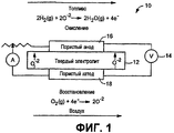
Фиг.1 представляет собой частичное изображение твердого топливного элемента на основе оксида (SOFC), включающего плотный электролит, который помещают между структурами пористых электродов;Figure 1 is a partial image of a solid oxide-based fuel cell (SOFC) comprising a dense electrolyte that is placed between structures of porous electrodes;
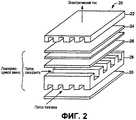
Фиг.2 представляет собой перспективное изображение блока SOFC, в котором несколько топливных элементов монтируют с внутренними соединителями, отделяющими каждый элемент;Figure 2 is a perspective view of an SOFC block in which several fuel cells are mounted with internal connectors separating each cell;
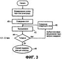
Фиг.3 представляет собой схему производственного процесса, в котором слой(и) пористого электрода формируют путем использования способа настоящего изобретения;Figure 3 is a diagram of a manufacturing process in which a porous electrode layer (s) are formed by using the method of the present invention;
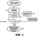
Фиг.4 представляет собой схему производственного процесса, в котором плотный(е) слой(и) электролита формируют на поверхности электрода, показанного на Фиг.3, путем использования способа настоящего изобретения, для создания электрод-электролитной би-слойной структуры;FIG. 4 is a flow chart of a process in which dense electrolyte layer (s) are formed on the surface of the electrode shown in FIG. 3 by using the method of the present invention to create an electrode-electrolyte bi-layer structure;
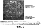
Фиг.5 представляет собой изображение электрод-электролитного би-слоя, формируемого согласно способу настоящего изобретения, как показано на схеме производственного процесса, представленной на Фиг.4;Figure 5 is an image of an electrode-electrolyte bi-layer formed according to the method of the present invention, as shown in the flowchart shown in Figure 4;
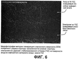
Фиг.6 представляет собой изображение, полученное с помощью сканирующего электронного микроскопа, электрод-электролитного би-слоя, формируемого согласно способу настоящего изобретения, как показано на схеме производственного процесса, представленной на Фиг.4;6 is an image obtained by scanning electron microscope, an electrode-electrolyte bi-layer formed according to the method of the present invention, as shown in the flowchart of FIG. 4;
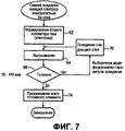
Фиг.7 представляет собой схему производственного процесса, в котором слой(и) пористого электрода осаждают на поверхность электролита, показанного на Фиг.4, где сформированную многослойную структуру нагревают и прокаливают в течение одного термического цикла согласно способу настоящего изобретения; иFIG. 7 is a flow chart of a process in which porous electrode layer (s) are deposited on the surface of the electrolyte shown in FIG. 4, where the formed multilayer structure is heated and calcined during one thermal cycle according to the method of the present invention; and
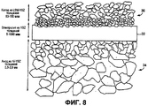
Фиг.8 представляет собой частичное изображение SOFC, изготавливаемого согласно способу, показанному на Фиг.3, 4 и 7, многослойного топливного элемента, включающего твердый электролит на основе циркония стабилизированного иттрием (YSZ), который помещают между катодом из манганита лантана, легированного стронцием-YSZ, и анодом из оксида никеля-YSZ.FIG. 8 is a partial view of a SOFC manufactured according to the method shown in FIGS. 3, 4 and 7 of a multilayer fuel cell comprising a solid yttrium stabilized zirconium electrolyte (YSZ) which is placed between a strontium-doped lanthanum manganite cathode YSZ, and nickel oxide anode-YSZ.
Подробное описание изобретенияDETAILED DESCRIPTION OF THE INVENTION
Настоящее изобретение представляет способ изготовления твердого топливного элемента на основе оксида (SOFC) в течение одного термического цикла. Этот цикл можно проводить в виде периодического процесса изготовления или в виде непрерывного процесса. SOFC можно удобно изготавливать согласно способу настоящего изобретения при стоимости, которая является меньшей, чем пятьсот долларов за киловатт электричества. Изготавливаемый SOFC функционирует также в диапазоне температур от около 700 до 1100°С. Аналогично согласно способу настоящего изобретения можно изготавливать блок SOFC, в котором несколько топливных элементов монтируют с внутренними соединителями, отделяющими каждый элемент. Устройства на основе топливных элементов, изготавливаемые с помощью раскрываемого способа, можно использовать, например, для питания воздухоплавательных систем, компьютерных устройств, самоходных систем и сотовых устройств.The present invention provides a method for manufacturing a solid oxide-based fuel cell (SOFC) in one thermal cycle. This cycle can be carried out as a periodic manufacturing process or as a continuous process. SOFCs can conveniently be manufactured according to the method of the present invention at a cost that is less than five hundred dollars per kilowatt of electricity. The produced SOFC also operates in the temperature range from about 700 to 1100 ° C. Similarly, according to the method of the present invention, it is possible to manufacture an SOFC unit in which several fuel cells are mounted with internal connectors separating each element. Fuel cell devices manufactured using the disclosed method can be used, for example, to power aeronautical systems, computer devices, self-propelled systems and cellular devices.
Предлагаемые топливные элементы представляют собой экологически чистый и многофункциональный источник энергии для эффективного превращения ископаемого топлива в электричество и тепло. Фиг.1 представляет собой SOFC 10, включающий плотный электролит 12, который помещают между пористыми электродами, а именно катодом 18 и анодом 16. Плотный электролит может быть твердым кислород-ионным проводником, таким как цирконий, стабилизированный иттрием (YSZ). Кроме того, катод и анод можно изготавливать из керамических композитных материалов, таких как манганит лантана, легированный стронцием-YSZ, и оксид никеля-YSZ соответственно. Топливный элемент генерирует электричество за счет электрохимической реакции, в которой кислород и водород соединяются с образованием воды. Конкретно электроды восстанавливают кислород и окисляют водород с получением разности потенциалов 14. Электроды могут также включать катализатор, такой как оксид никеля. Этот катализатор может ускорять и повышать эффективность электрохимической реакции.The fuel cells offered are an environmentally friendly and multi-functional energy source for the efficient conversion of fossil fuels into electricity and heat. 1 is a
Фиг.2 представляет собой блок 20 SOFC, в котором несколько топливных элементов монтируют с внутренними соединителями, отделяющими каждый элемент. Единичный топливный элемент в плоских блоках включает электролит 25, который помещают между катодом 26 и анодом 24. Внутренний соединительный компонент может быть обкладкой 22 или прокладкой 28, которая направляет потоки топлива и оксиданта сквозь блок. Эти внутренние соединители состоят обычно из композитных материалов, таких как, например, хромит лантана.Figure 2 is an
Способ настоящего изобретения включает формирование электрода за счет контролируемого распределения фаз и размеров частиц с созданием термофизически консистентного слоя, имеющего, например, однородную микроструктуру, эластичность и/или коэффициент теплового расширения. Консистенция, среди этих свойств, предохраняет электрод от деформирования и разрушения в процессе термического цикла. Способ также гармонизирует и сводит к минимуму отклонения среди термофизических свойств слоев электролита и электрода. Эта гармонизация снижает и сводит к минимуму температурный градиент топливного элемента в ходе термического цикла, так что структуру можно равномерно нагревать и прокаливать эффективным образом.The method of the present invention includes forming an electrode by controlling the distribution of phases and particle sizes to create a thermophysically consistent layer having, for example, a uniform microstructure, elasticity and / or coefficient of thermal expansion. Consistency, among these properties, protects the electrode from deformation and destruction during the thermal cycle. The method also harmonizes and minimizes deviations among the thermophysical properties of the electrolyte and electrode layers. This harmonization reduces and minimizes the temperature gradient of the fuel cell during the thermal cycle, so that the structure can be uniformly heated and calcined in an efficient manner.
Электрод представляет собой предпочтительно пористый анод, такой как показанный на Фиг.1 и 2. Пористый анод может состоять также из однослойного или многослойного композитного материала, такого как, например, оксид никеля-YSZ, оксид церия, легированный оксидом никель-гадолиния, оксид церия легированный оксидом никель-самария, оксид церия, легированный оксидом кобальта-YSZ или оксидом кобальт-гадолиния.The electrode is preferably a porous anode, such as that shown in FIGS. 1 and 2. The porous anode can also consist of a single-layer or multilayer composite material, such as, for example, nickel oxide-YSZ, cerium oxide doped with nickel-gadolinium oxide, cerium oxide doped with nickel-samarium oxide, cerium oxide doped with cobalt oxide-YSZ or cobalt-gadolinium oxide.
Электрод из композитного материала осаждают в виде свежего слоя(ев), имеющего(их) предпочтительную толщину в диапазоне около 0,5-2,0 мм. Эта толщина электрода служит механической опорой для топливного элемента. Толщина может зависеть от слоев пленочного литья, предпочтительно используемых при изготовлении электрода. Эти слои можно отливать также с изменяющейся пористостью для контролирования явления перемещения газа.An electrode of composite material is deposited in the form of a fresh layer (s) having (their) preferred thickness in the range of about 0.5-2.0 mm. This electrode thickness serves as a mechanical support for the fuel cell. The thickness may depend on the layers of film casting, preferably used in the manufacture of the electrode. These layers can also be molded with varying porosity to control the phenomenon of gas movement.
В основном слои пленочного литья формируют путем осаждения порошкообразной взвеси на субстрат, имеющий высвобождающийся материал. Взвесь может включать связующий агент, дисперсант, растворитель, пластификатор и композитные твердые вещества. Связующий агент может быть, например, поливиниловым спиртом или поливинилбутиралем. Обычный растворитель может включать этанол, толуол, метанол или изопропанол. Дисперсант или диспергирующий "агент" может включать рыбий жир. Эти материалы измельчают и просеивают для удаления мягких агломератов. Хоппер способствует перемещению взвеси на субстрат, а "ракельный нож" равномерно распределяет взвесь для отливки слоя. Этот слой затем отделяют от субстрата и подравнивают в соответствии с электродом.In general, film casting layers are formed by depositing a powdery suspension on a substrate having release material. Suspension may include a binder, dispersant, solvent, plasticizer and composite solids. The coupling agent may be, for example, polyvinyl alcohol or polyvinyl butyral. A typical solvent may include ethanol, toluene, methanol or isopropanol. The dispersant or dispersant "agent" may include fish oil. These materials are ground and sieved to remove soft agglomerates. The hopper helps to move the suspension onto the substrate, and the doctor blade evenly distributes the suspension to cast the layer. This layer is then separated from the substrate and trimmed in accordance with the electrode.
На схеме производственного процесса, представленной на Фиг.3, показан слой пленочного литья, создаваемый на стадии 40. Слой высушивают с помощью соответствующей технологии во время стадии 42 в диапазоне температур от около 100 до 400°С. При этом диапазоне температур происходит предпочтительно испарение соединений в отлитом слое, таких как дисперсант, растворитель и пластификатор, с формированием пористого электрода. Этот диапазон температур может также изменяться в зависимости от летучести этих материалов. Толщину электрода можно после этого измерять на стадии 44 с помощью подходящего способа, такого как, например, использование оптического или сканирующего электронного микроскопа.In the flowchart of FIG. 3, the film casting layer created in
На стадии 45 можно осаждать на электрод дополнительные слои пленочного литья и отдельно высушивать до тех пор, пока толщина не будет находиться в предпочтительном диапазоне около 0,5-2,0 мм. Как описано выше, эти дополнительные слои можно отливать с изменяющейся пористостью для контролирования явления перемещения газа и повышения эффективности электрода. Является предпочтительным, когда электроды имеют меньшую пористость вблизи к электролиту и когда пористость возрастает в направлении к их наружным поверхностям. Формируемую на стадии 46 структуру электрода в виде одного или составного слоя затем готовят для дальнейшей обработки согласно способу настоящего изобретения.In
На Фиг.4 показана схема производственного процесса, в котором плотный электролит формируют на слое(ях) электрода, создаваемом(ых) согласно способу настоящего изобретения. Этот электролит может быть однослойным или многослойным твердым проводником, таким, как показанный на Фиг.1 и 2. Примеры материалов такого твердого проводника включают YSZ, оксид церия-гадолиния, стронций, галлат магния лантана или оксид церия, легированный редкоземельным металлом. Проводник из YSZ работает эффективно в диапазоне температур от около 700 до 1100°С, хотя этот диапазон может изменяться для различных твердых электролитов.Figure 4 shows a diagram of a manufacturing process in which a dense electrolyte is formed on the electrode layer (s) created (s) according to the method of the present invention. This electrolyte may be a single-layer or multi-layer solid conductor, such as that shown in FIGS. 1 and 2. Examples of materials of such a solid conductor include YSZ, cerium-gadolinium oxide, strontium, lanthanum magnesium gallate or rare-earth alloyed cerium oxide. The YSZ conductor works efficiently in the temperature range from about 700 to 1100 ° C, although this range can vary for various solid electrolytes.
На стадии 50 слой(и) электролита можно формировать способом трафаретной печати на поверхности электрода в виде порошкообразной взвеси. Трафаретная печать контролирует распределение фаз и размеров частиц для создания консистентной термофизической структуры. Осаждаемый электролит имеет предпочтительно толщину в диапазоне около 5-1000 мкм. Эта толщина зависит от различных характеристик печати, таких как, например, содержание твердых веществ в композитном материале или распределение частиц в слое(ях).At
Порошкообразная взвесь для электролита может включать связующий агент, дисперсант, растворитель, пластификатор и твердые композитные материалы. Как описано выше, эти материалы измельчают и просеивают для удаления мягких агломератов перед печатанием. Слой взвеси, формируемый с помощью трафаретной печати, сушат в течение стадии 52 в диапазоне температур от около 100 до 400°С. Предпочтительно при этом диапазоне температур происходит испарение соединений в отпечатанном слое с формированием плотного электролита. После этого толщину электролита можно измерять на стадии 54 с помощью подходящего способа, включая способы, описанные ранее.Powdered suspension for electrolyte may include a binder, dispersant, solvent, plasticizer and solid composite materials. As described above, these materials are ground and sieved to remove soft agglomerates before printing. The suspension layer formed by screen printing is dried during
Электролит можно формировать путем осаждения дополнительных, получаемых с помощью трафаретной печати слоев на стадии 56. Каждый из этих слоев сушат до тех пор, пока толщина не будет находиться в предпочтительном диапазоне около 5-1000 мкм. Печатание дополнительных слоев можно изменять для контролирования явления перемещения газа и повышения эффективности электролита. Сформированную на стадии 60 структуру би-слоя готовят после этого для дальнейшей обработки согласно способу настоящего изобретения.The electrolyte can be formed by depositing additional layers obtained by screen printing on
Пример этой структуры электрод-элекролитного би-слоя представлен на Фиг.5 и 6. На Фиг.5 показан электрод в виде пористого анода, состоящий из полученного(ых) в результате пленочного литья слоя(ев) оксида никеля-YSZ. Слой(и) электролита формируют, используя трафаретную печать, на поверхности анода. Этот электролит является твердым проводником из YSZ. Фиг.6 представляет собой изображение этой би-слойной структуры, полученное с помощью сканирующего электронного микроскопа.An example of this electrode-electrolyte bi-layer structure is shown in Figs. 5 and 6. Fig. 5 shows a porous anode electrode, consisting of the nickel oxide-YSZ layer (s) obtained by film casting. The electrolyte layer (s) are formed using screen printing on the surface of the anode. This electrolyte is a solid conductor of YSZ. 6 is an image of this bilayer structure obtained using a scanning electron microscope.
Затем на электролит с би-слойной структурой осаждают второй электрод. На схеме производственного процесса, изображенной на Фиг.7, показан электрод, формируемый на поверхности слоя(ев) электролита в течение стадии 62. Электрод формируют путем контролируемого распределения фаз и размеров частиц. Сформированный электрод представляет собой предпочтительно пористый катод, такой как показанный на Фиг.1 и 2. Пористый катод может состоять из однослойного или многослойного композитного материала, такого как, например, манганит лантана, легированный стронцием-YSZ.Then, a second electrode is deposited on the electrolyte with a bilayer structure. The production process diagram shown in Fig. 7 shows an electrode formed on the surface of the electrolyte layer (s) during
Электрод из композитного материала можно изготавливать путем трафаретного печатания в виде слоя (ев), имеющего(их) предпочтительную толщину в диапазоне около 50-150 мкм. Эта толщина зависит от печатаемых слоев, используемых для формирования электрода. Электрод осаждают в виде порошкообразной взвеси, которая может включать связующий агент, дисперсант, растворитель, пластификатор и твердые композитные материалы. Эти материалы измельчают и просеивают для удаления мягких агломератов перед печатанием. Как было показано, слой осажденной взвеси сушат в течение стадии 64 в диапазоне температур от около 100 до 400°С. Предпочтительно при этом диапазоне температур происходит испарение соединений в отпечатанном слое с образованием пористого электрода. После этого толщину электрода можно измерять на стадии 66 с помощью подходящего способа, включая способы, описанные ранее.The electrode of the composite material can be made by screen printing in the form of a layer (s) having (their) preferred thickness in the range of about 50-150 microns. This thickness depends on the printable layers used to form the electrode. The electrode is deposited in the form of a powdered suspension, which may include a binder, dispersant, solvent, plasticizer and solid composite materials. These materials are ground and sieved to remove soft agglomerates before printing. As shown, the precipitated slurry layer was dried during
Электрод можно формировать на стадии 70 путем печатания дополнительных слоев на электролите и высушивания каждого слоя до тех пор, пока толщина не будет находиться в предпочтительном диапазоне около 50-150 мкм. Как описано выше, эти дополнительные слои можно осаждать, создавая различную пористость, для контролирования явления перемещения газа и воздействия на эффективность электрода. Эта однослойная или многослойная структура электрода, формируемая на электрод-электролитном би-слое, составляет многослойную структуру топливного элемента.The electrode can be formed in
Эта многослойная структура включает обычно плотный электролит, который помещают между пористыми электродами. Любая влага внутри многослойного топливного элемента предпочтительно испаряется при однородном нагревании структуры в диапазоне температур от около 125 до 150°С. Структуру можно также нагревать для удаления связующего агента из каждого слоя топливного элемента в диапазоне температур от около 275 до 375°С. При этом диапазоне температур происходит улетучивание любого пластификатора, дисперсанта или растворителя, остающегося внутри каждого слоя. Вещества связующего агента, которые подвергаются частому нагреванию, оставляют остаток углерода, который можно удалять при равномерном нагревании структуры в диапазоне температур от около 500 до 600°С. Это равномерное нагревание продолжают до тех пор, пока температура не достигнет 800°С для того, чтобы уменьшить время, требуемое для проведения термического цикла, и повысить эффективность метода. После этого на стадии 74 структуру прокаливают в диапазоне температур от около 1000 до 1500°С для спекания многослойной структуры. Количество времени, используемое для нагревания и прокаливания структуры в течение вышеописанных диапазонов температур, может изменяться в зависимости, например, от материалов топливного элемента или конкретного процесса.This multilayer structure typically includes a dense electrolyte that is placed between the porous electrodes. Any moisture inside the multilayer fuel cell is preferably evaporated by uniformly heating the structure in the temperature range from about 125 to 150 ° C. The structure can also be heated to remove the binder from each layer of the fuel cell in the temperature range from about 275 to 375 ° C. In this temperature range, any plasticizer, dispersant or solvent that remains inside each layer will volatilize. The substances of the binding agent, which are subjected to frequent heating, leave a carbon residue, which can be removed by uniformly heating the structure in the temperature range from about 500 to 600 ° C. This uniform heating is continued until the temperature reaches 800 ° C in order to reduce the time required for the thermal cycle and to increase the efficiency of the method. After that, at
Структуру топливного элемента можно равномерно нагревать с помощью источника микроволн переменной частоты или многочастотного источника микроволн. Такие источники микроволн описаны, в основном, в патентах США под номерами 5321222, 5521360 и 5961871. Уровень частоты и мощности источника микроволн можно регулировать для обеспечения эффективной передачи энергии микроволн в структуру топливного элемента. Частоту микроволн также можно модулировать или плавно изменять частотный диапазон для создания нужного спектра микроволн. Альтернативно можно предусматривать микроволновую энергию на многих частотах. Хотя микроволновой источник нагревания используют предпочтительно для равномерного нагревания многослойной структуры, можно использовать и другие подходящие процессы нагревания, которые сводят к минимуму температурный градиент внутри слоев топливного элемента.The fuel cell structure can be uniformly heated using a variable frequency microwave source or a multi-frequency microwave source. Such microwave sources are described mainly in US patents nos. 5321222, 5521360 and 5961871. The frequency and power level of the microwave source can be adjusted to ensure efficient transfer of microwave energy to the fuel cell structure. The frequency of microwaves can also be modulated or smoothly changed the frequency range to create the desired spectrum of microwaves. Alternatively, microwave energy may be provided at multiple frequencies. Although a microwave heating source is preferably used to uniformly heat the multilayer structure, other suitable heating processes that minimize the temperature gradient within the layers of the fuel cell can be used.
Многослойный топливный элемент можно прокаливать за счет конвекционного и/или излучаемого нагрева, такого как нагрев, используемый в процессе обжига керамики. Эти способы нагрева можно осуществлять также в атмосфере циркулирующего газа. Температуры для прокаливания SOFC могут зависеть от термофизических свойств слоев электролита и электрода. Таким образом, различные электрические нагреватели, такие как, например, изготовленные из никель-хрома, молибденовой ленты, молибден-силиката или карбидокремния, можно использовать для определенных структур топливного элемента.The multilayer fuel cell can be calcined by convection and / or radiated heating, such as the heat used in the ceramic firing process. These heating methods can also be carried out in a circulating gas atmosphere. Temperatures for calcining SOFCs may depend on the thermophysical properties of the electrolyte and electrode layers. Thus, various electric heaters, such as, for example, made of nickel-chromium, molybdenum tape, molybdenum silicate or silicon carbide, can be used for certain fuel cell structures.
Согласно способу настоящего изобретения проводится нагревание и прокаливание многослойного топливного элемента в течение одного термического цикла. Этот термический цикл можно проводить в печи, имеющей одну или большее количество камер. Камера(ы) предпочтительно содержит(ат) источник микроволн переменной частоты или многочастотный источник микроволн для нагревания топливного элемента и удаления связующих соединений в структурах электролита и электрода. Камера(ы) печи предпочтительно включает(ют) источник конвекционного нагрева и/или радиационного нагрева для спекания топливного элемента. Такие печи описывают в патентной заявке США за номером 10/775542, переуступленной BTU International, Incorporated. Единичный термический цикл можно осуществлять также в виде периодического или непрерывного процесса изготовления.According to the method of the present invention, heating and calcination of a multilayer fuel cell is carried out during one thermal cycle. This thermal cycle can be carried out in a furnace having one or more chambers. The chamber (s) preferably comprises (at) a variable frequency microwave source or a multi-frequency microwave source for heating the fuel cell and removing binder compounds in the electrolyte and electrode structures. The furnace chamber (s) preferably includes (are) a source of convection heating and / or radiation heating for sintering the fuel cell. Such furnaces are described in US Patent Application No. 10/775542, assigned to BTU International, Incorporated. A single thermal cycle can also be carried out in the form of a periodic or continuous manufacturing process.
Электролит многослойной структуры топливного элемента представляет собой предпочтительно твердый проводник, состоящий из 8 мольных процентов YSZ, а катод и анод состоят из керамических композитных материалов, таких как манганит лантана, легированный стронцием-YSZ, и оксид никеля-YSZ соответственно. Слои электролита и электрода выбирают таким образом, чтобы они имели размер частиц в диапазоне нанометров или микрометров. На Фиг.8 показан SOFC, изготовленный из этих материалов, в процессе его формирования и прокаливания. Предпочтительная толщина плотного электролита и каждого пористого электрода также показана.The multilayer fuel cell electrolyte is preferably a solid conductor consisting of 8 mole percent YSZ, and the cathode and anode are composed of ceramic composite materials such as strontium-doped manganite-YSZ and nickel oxide-YSZ, respectively. The layers of electrolyte and electrode are selected so that they have a particle size in the range of nanometers or micrometers. On Fig shows a SOFC made from these materials in the process of its formation and calcination. A preferred thickness of the dense electrolyte and each porous electrode is also shown.
Параметры процесса настоящего изобретения также можно изменять для того, чтобы, например, уменьшать время, требуемое для термического цикла, и чтобы повышать эффективность изготовления. Эти параметры могут включать температуру, время, атмосферу, размер частиц и/или распределение частиц. Модифицирование этих параметров может также оказывать воздействие и улучшать граничный контакт и устойчивость между слоями, а также уменьшать внутренние напряжения для предотвращения деформирования многослойной структуры. Способ настоящего изобретения можно использовать при участии в технологическом процессе вспомогательного устройства, поддерживающего температуру SOFC, которое имеет, например, насосы для кислорода, датчики, или при участии других электрохимических устройств.The process parameters of the present invention can also be changed in order, for example, to reduce the time required for the thermal cycle, and in order to increase the manufacturing efficiency. These parameters may include temperature, time, atmosphere, particle size and / or particle distribution. Modification of these parameters can also affect and improve the boundary contact and stability between the layers, as well as reduce internal stresses to prevent deformation of the multilayer structure. The method of the present invention can be used with the participation in the process of an auxiliary device that maintains the temperature of SOFC, which has, for example, oxygen pumps, sensors, or with the participation of other electrochemical devices.
В то время как настоящее изобретение было описано в связи с предпочтительным вариантом осуществления настоящего изобретения, любой специалист в данной области, после ознакомления с вышеприведенным описанием, будет способен произвести различные изменения, замены эквивалентов и другие вариации по отношению к композициям и изделиям, представленным в нем. Следовательно, предполагается, что защита, предоставляемая патентом на изобретение, будет ограничиваться лишь определениями, содержащимися в прилагаемой Формуле изобретения и ее эквивалентах.While the present invention has been described in connection with a preferred embodiment of the present invention, any person skilled in the art, after reading the above description, will be able to make various changes, replacements of equivalents, and other variations with respect to the compositions and products presented therein . Therefore, it is intended that the protection afforded by a patent for an invention be limited only by the definitions contained in the appended claims and their equivalents.
Claims (34)
формирование первого слоя электрода с поверхностью, который перед прокаливанием имеет толщину в диапазоне около 0,5-2,0 мм;
формирование слоя электролита трафаретной печатью порошкообразной взвеси на поверхности первого слоя электрода;
формирование второго слоя электрода на поверхности слоя электролита, при этом слои составляют многослойную электрохимическую структуру;
нагревание многослойной структуры для существенного удаления связующего агента и других материалов из каждого слоя; и
прокаливание многослойной структуры для существенного спекания каждого слоя.1. A method of manufacturing a solid oxide fuel cell, comprising the following steps in the following sequence:
the formation of the first layer of the electrode with the surface, which before calcination has a thickness in the range of about 0.5-2.0 mm;
the formation of an electrolyte layer by screen printing of a powdered suspension on the surface of the first electrode layer;
the formation of the second electrode layer on the surface of the electrolyte layer, while the layers make up a multilayer electrochemical structure;
heating the multilayer structure to substantially remove the binding agent and other materials from each layer; and
calcination of the multilayer structure for substantial sintering of each layer.
осаждение взвеси для формирования каждого слоя, включающей связующий агент, дисперсант, растворитель, пластификатор и композитные твердые вещества; и
высушивание осажденной взвеси для существенного удаления дисперсанта, растворителя и пластификатора.2. The method according to claim 1, further comprising:
sedimentation of the suspension to form each layer, including a binding agent, dispersant, solvent, plasticizer and composite solids; and
drying the precipitated suspension to substantially remove the dispersant, solvent and plasticizer.
высушивание первого слоя, который высушивают перед осаждением материала электролита, и высушенный первый слой имеет определенную толщину.17. The method according to claim 1, further comprising:
drying the first layer, which is dried before the electrolyte material is deposited, and the dried first layer has a certain thickness.
высушивание материала электролита, который высушивают перед осаждением второго слоя, и высушенный материал электролита имеет определенную толщину.18. The method according to claim 1, further comprising:
drying the electrolyte material, which is dried before the second layer is deposited, and the dried electrolyte material has a certain thickness.
высушивание второго слоя, который высушивают перед прокаливанием многослойной структуры, и высушенный второй слой имеет определенную толщину.19. The method according to claim 1, further comprising:
drying the second layer, which is dried before calcining the multilayer structure, and the dried second layer has a certain thickness.
измерение определенной толщины высушенного первого слоя для сравнения с требуемой толщиной;
получение дополнительного слоя электрохимически активного материала на высушенном первом слое, при этом дополнительный слой включает связующий агент, дисперсант, растворитель, пластификатор и композитные твердые вещества;
высушивание дополнительного слоя;
измерение определенной толщины слоев для сравнения с требуемой толщиной; и
повторение стадий получения и высушивания слоев до тех пор, пока определенная толщина и требуемая толщина слоев не будут примерно равными.20. The method according to 17, further comprising:
measuring a specific thickness of the dried first layer for comparison with the desired thickness;
obtaining an additional layer of electrochemically active material on the dried first layer, the additional layer comprising a binding agent, dispersant, solvent, plasticizer and composite solids;
drying the additional layer;
measurement of a certain thickness of layers for comparison with the required thickness; and
repeating the steps of preparing and drying the layers until a certain thickness and a desired layer thickness are approximately equal.
измерение определенной толщины высушенного материала электролита для сравнения с требуемой толщиной;
получение дополнительного материала на высушенном материале электролита, при этом дополнительный материал включает связующий агент, дисперсант, растворитель, пластификатор и композитные твердые вещества;
высушивание дополнительного материала;
измерение определенной толщины материалов для сравнения с требуемой толщиной; и
повторение стадий получения и высушивания материалов до тех пор, пока определенная толщина и требуемая толщина материалов не будут примерно равными.21. The method according to p, further comprising:
measuring a specific thickness of the dried electrolyte material for comparison with the desired thickness;
obtaining additional material on the dried electrolyte material, the additional material includes a binder, dispersant, solvent, plasticizer and composite solids;
drying additional material;
measuring a specific thickness of materials for comparison with the required thickness; and
repeating the steps of preparing and drying the materials until the specific thickness and the required thickness of the materials are approximately equal.
измерение определенной толщины высушенного второго слоя для сравнения с требуемой толщиной;
получение дополнительного слоя электрохимически активного материала на высушенном втором слое, при этом дополнительный слой включает связующий агент, дисперсант, растворитель, пластификатор и композитные твердые вещества;
высушивание дополнительного слоя;
измерение определенной толщины слоев для сравнения с требуемой толщиной; и
повторение стадий получения и высушивания слоев до тех пор, пока определенная толщина и требуемая толщина слоев не будут примерно равными.22. The method according to claim 19, further comprising:
measuring a specific thickness of the dried second layer for comparison with the desired thickness;
obtaining an additional layer of electrochemically active material on the dried second layer, the additional layer comprising a binding agent, dispersant, solvent, plasticizer and composite solids;
drying the additional layer;
measurement of a certain thickness of layers for comparison with the required thickness; and
repeating the steps of preparing and drying the layers until a certain thickness and a desired layer thickness are approximately equal.
осуществление способа по п.1;
помещение внутреннего соединителя на поверхность многослойной электрохимической структуры; и
повторение способа по п.1, при этом внутренний соединитель существенно разделяет многослойные структуры.23. A method of manufacturing a block of solid fuel cells based on oxide, including:
the implementation of the method according to claim 1;
placing the internal connector on the surface of the multilayer electrochemical structure; and
repeating the method of claim 1, wherein the inner connector substantially separates the multilayer structures.
пористый анод, имеющий толщину перед прокаливанием в диапазоне около 0,5-2,0 мм;
твердый электролит, помещаемый на поверхность анода, имеющий толщину перед прокаливанием в диапазоне около 5-1000 мкм; и
пористый катод, помещаемый на поверхность электролита, имеющий толщину перед прокаливанием в диапазоне около 50-150 мкм, при этом анод, электролит и катод изготавливают способом по п.1.24. A solid oxide-based fuel cell capable of converting chemical energy into electricity and heat, including:
a porous anode having a thickness before calcination in the range of about 0.5-2.0 mm;
a solid electrolyte placed on the surface of the anode having a thickness before calcination in the range of about 5-1000 microns; and
a porous cathode placed on the surface of the electrolyte having a thickness before calcination in the range of about 50-150 μm, wherein the anode, electrolyte and cathode are made by the method according to claim 1.
формирование би-слоя, состоящего из первого пористого слоя электрода и материала плотного электролита на поверхности первого слоя электрода;
формирование второго пористого слоя электрода на поверхности материала электролита для получения многослойной электрохимической структуры, имеющей материал электролита, помещенный между первым и вторым слоями электрода;
термической обработки многослойной электрохимической структуры для существенного удаления связующего агента и других материалов из первого и второго слоев электрода и из материала электролита, и для существенного спекания многослойной электрохимической структуры.25. A method of manufacturing a solid oxide fuel cell comprising the following steps:
the formation of a bi-layer consisting of a first porous electrode layer and a dense electrolyte material on the surface of the first electrode layer;
forming a second porous electrode layer on the surface of the electrolyte material to obtain a multilayer electrochemical structure having an electrolyte material placed between the first and second electrode layers;
heat treatment of the multilayer electrochemical structure to substantially remove the binder and other materials from the first and second layers of the electrode and from the electrolyte material, and to substantially sinter the multilayer electrochemical structure.
формирование многослойной электрохимической структуры, имеющей слой электролита, помещенный между первым и вторым слоями электрода; и
термической обработки многослойной электрохимической структуры для существенного удаления связующего агента и других материалов из первого и второго слоев электрода и из материала электролита, и для существенного спекания многослойной электрохимической структуры.26. A method of manufacturing a solid oxide fuel cell comprising the following steps:
forming a multilayer electrochemical structure having an electrolyte layer interposed between the first and second electrode layers; and
heat treatment of the multilayer electrochemical structure to substantially remove the binder and other materials from the first and second layers of the electrode and from the electrolyte material, and to substantially sinter the multilayer electrochemical structure.
формирование первого слоя электрода, имеющего поверхность;
формирование слоя электролита на поверхности первого слоя электрода;
формирование второго слоя электрода на поверхности слоя электролита, при этом слои составляют многослойную электрохимическую структуру;
нагревание многослойной электрохимической структуры для существенного удаления связующего агента и других материалов из каждого слоя; и
прокаливание многослойной электрохимической структуры для существенного спекания слоев.27. A method of manufacturing a solid oxide fuel cell, comprising:
forming a first electrode layer having a surface;
the formation of an electrolyte layer on the surface of the first electrode layer;
the formation of the second electrode layer on the surface of the electrolyte layer, while the layers make up a multilayer electrochemical structure;
heating the multilayer electrochemical structure to substantially remove the binder and other materials from each layer; and
calcining a multilayer electrochemical structure for substantial sintering of the layers.
стадия формирования первого слоя электрода включает формирование керамического композитного материала, имеющего толщину перед прокаливанием в диапазоне около 0,5-2,0 мм;
стадия формирования слоя электролита включает формирование слоя электролита, имеющего толщину перед прокаливанием в диапазоне около 5-1000 мкм; и
стадия формирования второго слоя электрода включает формирование слоя керамического композитного материала, имеющего толщину перед прокаливанием в диапазоне около 50-150 мкм.30. The method according to item 27, wherein
the step of forming the first electrode layer comprises forming a ceramic composite material having a thickness before calcination in the range of about 0.5-2.0 mm;
the step of forming the electrolyte layer includes forming an electrolyte layer having a thickness before calcination in the range of about 5-1000 microns; and
the step of forming the second electrode layer includes forming a layer of ceramic composite material having a thickness before calcination in the range of about 50-150 microns.
получение первого слоя электрода электрохимически активного материала, имеющего поверхность;
осаждение слоя материала электролита на поверхность первого слоя
электрода;
осаждение второго слоя электрода электрохимически активного материала на поверхность материала электролита, при этом материал электролита помещают между слоями электрода для создания многослойной электрохимической структуры; и
термической обработки многослойной электрохимической структуры для существенного удаления связующего агента и других материалов из каждого слоя, и для существенного спекания слоев.32. A method of manufacturing a solid oxide fuel cell, comprising:
obtaining a first electrode layer of an electrochemically active material having a surface;
deposition of a layer of electrolyte material on the surface of the first layer
an electrode;
the deposition of the second electrode layer of the electrochemically active material on the surface of the electrolyte material, while the electrolyte material is placed between the electrode layers to create a multilayer electrochemical structure; and
heat treating the multilayer electrochemical structure to substantially remove the binder and other materials from each layer, and to substantially sinter the layers.
высушивание каждого слоя перед каждой последующей стадией. 34. The method according to claim 1, further comprising:
drying each layer before each subsequent step.
Applications Claiming Priority (2)
| Application Number | Priority Date | Filing Date | Title |
|---|---|---|---|
| US50174203P | 2003-09-10 | 2003-09-10 | |
| US60/501,742 | 2003-09-10 |
Publications (2)
| Publication Number | Publication Date |
|---|---|
| RU2006110158A RU2006110158A (en) | 2007-10-20 |
| RU2362239C2 true RU2362239C2 (en) | 2009-07-20 |
Family
ID=34312303
Family Applications (1)
| Application Number | Title | Priority Date | Filing Date |
|---|---|---|---|
| RU2006110158/09A RU2362239C2 (en) | 2003-09-10 | 2004-09-10 | Method of making solid-oxide fuel cell |
Country Status (11)
| Country | Link |
|---|---|
| US (1) | US7485385B2 (en) |
| EP (1) | EP1671385B1 (en) |
| JP (1) | JP5015598B2 (en) |
| KR (1) | KR101136191B1 (en) |
| CN (1) | CN101061596B (en) |
| AU (1) | AU2004272186B8 (en) |
| BR (1) | BRPI0414240A (en) |
| CA (1) | CA2538224C (en) |
| CR (1) | CR8281A (en) |
| RU (1) | RU2362239C2 (en) |
| WO (1) | WO2005027239A2 (en) |
Families Citing this family (46)
| Publication number | Priority date | Publication date | Assignee | Title |
|---|---|---|---|---|
| US7550217B2 (en) | 2003-06-09 | 2009-06-23 | Saint-Gobain Ceramics & Plastics, Inc. | Stack supported solid oxide fuel cell |
| JP5260052B2 (en) * | 2004-06-10 | 2013-08-14 | テクニカル ユニバーシティ オブ デンマーク | Solid oxide fuel cell |
| US8002166B2 (en) * | 2004-12-28 | 2011-08-23 | Technical University Of Denmark | Method of producing metal to glass, metal to metal or metal to ceramic connections |
| ES2326601T3 (en) * | 2005-01-12 | 2009-10-15 | Technical University Of Denmark | PROCEDURE FOR THE CONTROL OF CONTRACTION AND POROSITY DURING THE SINTERIZATION OF MULTI-PAPER STRUCTURES. |
| WO2006079558A1 (en) * | 2005-01-31 | 2006-08-03 | Technical University Of Denmark | Redox-stable anode |
| DE602006013786D1 (en) * | 2005-02-02 | 2010-06-02 | Univ Denmark Tech Dtu | METHOD FOR PRODUCING A REVERSIBLE SOLID OXYGEN FUEL CELL |
| WO2007005767A1 (en) * | 2005-07-01 | 2007-01-11 | The Regents Of The University Of California | Advanced solid oxide fuel cell stack design for power generation |
| EP1760817B1 (en) * | 2005-08-31 | 2013-08-21 | Technical University of Denmark | Reversible solid oxide fuell cell stack and method for preparing same |
| EP1936723B1 (en) * | 2005-09-20 | 2013-06-05 | Kyocera Corporation | Process for producing a fuel cell |
| HUP0501201A2 (en) * | 2005-12-23 | 2007-07-30 | Cella H | Electrode for electrochemical cell working with high differential pressure difference, method for producing said electrode and electrochemical cell for using said electrode |
| EP1930974B1 (en) * | 2006-11-23 | 2012-03-21 | Technical University of Denmark | Method for the manufacture of reversible solid oxide cells |
| EP1928049A1 (en) | 2006-11-23 | 2008-06-04 | Technical University of Denmark | Thin solid oxide cell |
| US20090181274A1 (en) * | 2006-12-12 | 2009-07-16 | Elangovan S | Electrodes for Lanthanum Gallate Electrolyte-Based Electrochemical Systems |
| US20080232032A1 (en) * | 2007-03-20 | 2008-09-25 | Avx Corporation | Anode for use in electrolytic capacitors |
| US20080248363A1 (en) * | 2007-04-06 | 2008-10-09 | Alfred University | Composite electrolyte material having high ionic conductivity and depleted electronic conductivity and method for producing same |
| ES2375407T3 (en) * | 2007-08-31 | 2012-02-29 | Technical University Of Denmark | SEPARATION OF IMPURITY PHASES OF ELECTROCHEMICAL DEVICES. |
| US20090110992A1 (en) * | 2007-10-30 | 2009-04-30 | Bloom Energy Corporation | SOFC electrode sintering by microwave heating |
| US20090151850A1 (en) * | 2007-12-14 | 2009-06-18 | Wei-Xin Kao | Process for fabrication of a fully dense electrolyte layer embedded in membrane electrolyte assembly of solid oxide fuel cell |
| US20110003084A1 (en) * | 2008-02-25 | 2011-01-06 | National Research Council Of Canada | Process of Making Ceria-Based Electrolyte Coating |
| EP2104165A1 (en) * | 2008-03-18 | 2009-09-23 | The Technical University of Denmark | An all ceramics solid oxide fuel cell |
| US8163437B2 (en) * | 2008-03-25 | 2012-04-24 | Fuelcell Energy, Inc. | Anode with ceramic additives for molten carbonate fuel cell |
| GB2469522A (en) * | 2009-04-17 | 2010-10-20 | Energy Conversion Technology As | Fuel cell apparatus and method for heating a fuel cell stack |
| EP2333883A1 (en) * | 2009-11-18 | 2011-06-15 | Forschungszentrum Jülich Gmbh (FJZ) | Anode for a high temperature fuel cell and production of same |
| KR101362894B1 (en) * | 2009-12-09 | 2014-02-14 | 한국세라믹기술원 | Fabrication of unit cell of the Solid Oxide Fuel Cell by Transcripition Method |
| DE102009057720A1 (en) | 2009-12-10 | 2011-06-16 | Siemens Aktiengesellschaft | Battery and method for operating a battery |
| US20130078448A1 (en) * | 2010-04-09 | 2013-03-28 | The Regents Of The University Of California | Method of making electrochemical device with porous metal layer |
| JP2012028088A (en) * | 2010-07-21 | 2012-02-09 | Sumitomo Electric Ind Ltd | Membrane electrode assembly, fuel cell, gas abatement device, and method of manufacturing membrane electrode assembly |
| ES2408861T3 (en) * | 2010-07-07 | 2013-06-21 | Technical University Of Denmark | Sintering Method |
| TWI531107B (en) * | 2010-08-17 | 2016-04-21 | 博隆能源股份有限公司 | Method for solid oxide fuel cell fabrication |
| JP2014154239A (en) * | 2013-02-05 | 2014-08-25 | Seiko Epson Corp | Method for manufacturing active material compact, active material compact, method for manufacturing lithium battery, and lithium battery |
| US10811717B2 (en) | 2013-02-13 | 2020-10-20 | Georgia Tech Research Corporation | Electrolyte formation for a solid oxide fuel cell device |
| US9356298B2 (en) | 2013-03-15 | 2016-05-31 | Bloom Energy Corporation | Abrasion resistant solid oxide fuel cell electrode ink |
| EP3038197A4 (en) * | 2013-08-21 | 2017-04-12 | Murata Manufacturing Co., Ltd. | Ceramic substrate for electrochemical element, method for manufacturing same, fuel cell, and fuel cell stack |
| US9660273B2 (en) | 2013-10-08 | 2017-05-23 | Phillips 66 Company | Liquid phase modification of solid oxide fuel cells |
| WO2015054024A1 (en) | 2013-10-08 | 2015-04-16 | Phillips 66 Company | Gas phase modification of solid oxide fuel cells |
| US10418657B2 (en) | 2013-10-08 | 2019-09-17 | Phillips 66 Company | Formation of solid oxide fuel cells by spraying |
| US20160362805A1 (en) * | 2013-11-01 | 2016-12-15 | Adam Clayton Powell, IV | Methods and apparatuses for increasing energy efficiency and improving membrane robustness in primary metal production |
| WO2015160751A1 (en) * | 2014-04-14 | 2015-10-22 | Ovonic Battery Company, Inc. | Shared electrode hybrid battery-fuel cell system |
| EP3893293B1 (en) * | 2016-06-07 | 2023-05-10 | Navitas Systems, Llc | High loading electrodes |
| KR102119411B1 (en) * | 2017-11-09 | 2020-06-08 | 한국화학연구원 | Method of manufacturing porous composite electrode and method of removing organic material from porous composite electrode |
| US11043338B2 (en) | 2017-11-09 | 2021-06-22 | Korea Research Institute Of Chemical Technology | Manufacturing method of porous composite electrode and organic removal method of porous composite electrode |
| DE102018217516A1 (en) * | 2018-10-12 | 2020-04-16 | Volkswagen Aktiengesellschaft | Method of manufacturing an electrode for an accumulator |
| DE102018217518A1 (en) * | 2018-10-12 | 2020-04-16 | Volkswagen Aktiengesellschaft | Method of manufacturing an electrode for an accumulator |
| CN109437903B (en) * | 2018-12-20 | 2022-01-18 | 云南大学 | Method for improving sintering activity of doped cerium oxide electrolyte |
| JP7168090B2 (en) * | 2019-08-06 | 2022-11-09 | 株式会社村田製作所 | Electrolyte sheet for solid oxide fuel cell, method for producing electrolyte sheet for solid oxide fuel cell, and single cell for solid oxide fuel cell |
| US20220231317A1 (en) * | 2021-01-15 | 2022-07-21 | Bloom Energy Corporation | Method of manufacturing solid oxide electrolyzer cells using a continuous furnace |
Family Cites Families (50)
| Publication number | Priority date | Publication date | Assignee | Title |
|---|---|---|---|---|
| US4000006A (en) * | 1975-09-02 | 1976-12-28 | United Technologies Corporation | Screen printing fuel cell electrolyte matrices |
| JPS5916831B2 (en) | 1978-07-24 | 1984-04-18 | 日産自動車株式会社 | Manufacturing method of membrane structure type oxygen sensor |
| US4799936A (en) * | 1987-06-19 | 1989-01-24 | Combustion Engineering, Inc. | Process of forming conductive oxide layers in solid oxide fuel cells |
| US4997726A (en) | 1989-02-15 | 1991-03-05 | Sanyo Electric Co., Ltd. | Solid oxide electrolyte fuel cell |
| US5069987A (en) | 1990-07-06 | 1991-12-03 | Igr Enterprises, Inc. | Solid oxide fuel cell assembly |
| US5290642A (en) | 1990-09-11 | 1994-03-01 | Alliedsignal Aerospace | Method of fabricating a monolithic solid oxide fuel cell |
| US5143801A (en) * | 1990-10-22 | 1992-09-01 | Battelle Memorial Institute | Solid oxide fuel cells, and air electrode and electrical interconnection materials therefor |
| US5292599A (en) | 1991-09-27 | 1994-03-08 | Ngk Insulators, Ltd. | Cell units for solid oxide fuel cells and power generators using such cell units |
| US5529856A (en) * | 1993-01-14 | 1996-06-25 | Electric Power Research Institute | Fuel cell having solidified plasma components |
| US5827620A (en) | 1993-03-20 | 1998-10-27 | Keele University | Solid oxide fuel cell structures |
| GB9403198D0 (en) | 1994-02-19 | 1994-04-13 | Rolls Royce Plc | A solid oxide fuel cell stack |
| GB9403234D0 (en) | 1994-02-19 | 1994-04-13 | Rolls Royce Plc | A solid oxide fuel cell stack and a reactant distribution member therefor |
| JPH07277849A (en) * | 1994-04-13 | 1995-10-24 | Ngk Insulators Ltd | Porous sintered compact, heat resistant electrode and solid electrolyte type fuel cell |
| US6316138B1 (en) | 1994-07-11 | 2001-11-13 | Mitsubishi, Jukogyo Kabushiki Kaisha | Solid oxide electrolyte fuel cell |
| EP0706878B1 (en) * | 1994-09-13 | 2000-08-23 | Gunze Limited | Laminate |
| US5725965A (en) * | 1995-04-25 | 1998-03-10 | Gas Research Institute | Stable high conductivity functionally gradient compositionally layered solid state electrolytes and membranes |
| US5993986A (en) | 1995-11-16 | 1999-11-30 | The Dow Chemical Company | Solide oxide fuel cell stack with composite electrodes and method for making |
| US5753385A (en) | 1995-12-12 | 1998-05-19 | Regents Of The University Of California | Hybrid deposition of thin film solid oxide fuel cells and electrolyzers |
| JPH09245813A (en) * | 1996-03-06 | 1997-09-19 | Nippon Telegr & Teleph Corp <Ntt> | Manufacture of solid electrolyte fuel cell |
| US6790474B1 (en) | 1996-12-20 | 2004-09-14 | Tokyo Gas Co., Ltd. | Fuel electrode of solid oxide fuel cell and process for the production of the same |
| US6228520B1 (en) | 1997-04-10 | 2001-05-08 | The Dow Chemical Company | Consinterable ceramic interconnect for solid oxide fuel cells |
| US5922486A (en) | 1997-05-29 | 1999-07-13 | The Dow Chemical Company | Cosintering of multilayer stacks of solid oxide fuel cells |
| US6099985A (en) | 1997-07-03 | 2000-08-08 | Gas Research Institute | SOFC anode for enhanced performance stability and method for manufacturing same |
| US6117302A (en) | 1998-08-18 | 2000-09-12 | Aluminum Company Of America | Fuel cell aluminum production |
| JP2000133280A (en) * | 1998-10-19 | 2000-05-12 | Sof Co | Anode for high performance solid oxide fuel cell |
| KR100341402B1 (en) | 1999-03-09 | 2002-06-21 | 이종훈 | Single Cell and Stack Structure of Solid Oxide Fuel Cell |
| US6682842B1 (en) | 1999-07-31 | 2004-01-27 | The Regents Of The University Of California | Composite electrode/electrolyte structure |
| US6605316B1 (en) | 1999-07-31 | 2003-08-12 | The Regents Of The University Of California | Structures and fabrication techniques for solid state electrochemical devices |
| KR100344936B1 (en) | 1999-10-01 | 2002-07-19 | 한국에너지기술연구원 | Tubular Solid Oxide Fuel Cell supported by Fuel Electrode and Method for the same |
| US6649296B1 (en) | 1999-10-15 | 2003-11-18 | Hybrid Power Generation Systems, Llc | Unitized cell solid oxide fuel cells |
| US6485852B1 (en) | 2000-01-07 | 2002-11-26 | Delphi Technologies, Inc. | Integrated fuel reformation and thermal management system for solid oxide fuel cell systems |
| DK174654B1 (en) | 2000-02-02 | 2003-08-11 | Topsoe Haldor As | Solid oxide fuel cell and its applications |
| US6428920B1 (en) | 2000-05-18 | 2002-08-06 | Corning Incorporated | Roughened electrolyte interface layer for solid oxide fuel cells |
| US7416802B2 (en) * | 2000-05-22 | 2008-08-26 | Acumentrics Corporation | Electrode-supported solid state electrochemical cell |
| JP3690967B2 (en) * | 2000-06-29 | 2005-08-31 | 株式会社日本触媒 | Slurry for forming solid electrolyte membrane and solid electrolyte membrane using the same |
| JP4605885B2 (en) | 2000-10-23 | 2011-01-05 | 東邦瓦斯株式会社 | Support membrane type solid oxide fuel cell |
| US6551734B1 (en) | 2000-10-27 | 2003-04-22 | Delphi Technologies, Inc. | Solid oxide fuel cell having a monolithic heat exchanger and method for managing thermal energy flow of the fuel cell |
| US6855451B2 (en) | 2000-11-08 | 2005-02-15 | Fuelcell Energy, Ltd. | Electrochemical cell interconnect |
| US6803141B2 (en) | 2001-03-08 | 2004-10-12 | The Regents Of The University Of California | High power density solid oxide fuel cells |
| US7638222B2 (en) | 2001-03-28 | 2009-12-29 | Hexis Ag | Porous, gas permeable layer substructure for a thin, gas tight layer for use as a functional component in high temperature fuel cells |
| US6677070B2 (en) | 2001-04-19 | 2004-01-13 | Hewlett-Packard Development Company, L.P. | Hybrid thin film/thick film solid oxide fuel cell and method of manufacturing the same |
| US20020155227A1 (en) | 2001-04-23 | 2002-10-24 | Sulzer Markets And Technolgy Ag | Method for the manufacture of a functional ceramic layer |
| JP5110337B2 (en) * | 2001-06-18 | 2012-12-26 | 株式会社豊田中央研究所 | Electrode structure for solid oxide fuel cell and method for producing the same |
| JP4840718B2 (en) | 2001-08-14 | 2011-12-21 | 日産自動車株式会社 | Solid oxide fuel cell |
| US6949307B2 (en) | 2001-10-19 | 2005-09-27 | Sfco-Efs Holdings, Llc | High performance ceramic fuel cell interconnect with integrated flowpaths and method for making same |
| US6653009B2 (en) | 2001-10-19 | 2003-11-25 | Sarnoff Corporation | Solid oxide fuel cells and interconnectors |
| YU88103A (en) | 2002-05-14 | 2006-08-17 | H.Lundbeck A/S. | Treatment adhd |
| US20030232230A1 (en) * | 2002-06-12 | 2003-12-18 | Carter John David | Solid oxide fuel cell with enhanced mechanical and electrical properties |
| US6893769B2 (en) * | 2002-12-18 | 2005-05-17 | Hewlett-Packard Development Company, L.P. | Fuel cell assemblies and methods of making the same |
| US7838166B2 (en) | 2003-03-31 | 2010-11-23 | Tokyo Gas Co., Ltd. | Method for fabricating solid oxide fuel cell module |
-
2004
- 2004-09-10 CA CA2538224A patent/CA2538224C/en not_active Expired - Lifetime
- 2004-09-10 JP JP2006526312A patent/JP5015598B2/en not_active Expired - Fee Related
- 2004-09-10 CN CN2004800328167A patent/CN101061596B/en not_active Expired - Fee Related
- 2004-09-10 US US10/939,116 patent/US7485385B2/en not_active Expired - Fee Related
- 2004-09-10 BR BRPI0414240-3A patent/BRPI0414240A/en not_active IP Right Cessation
- 2004-09-10 KR KR1020067005088A patent/KR101136191B1/en not_active IP Right Cessation
- 2004-09-10 AU AU2004272186A patent/AU2004272186B8/en not_active Ceased
- 2004-09-10 WO PCT/US2004/029571 patent/WO2005027239A2/en active Application Filing
- 2004-09-10 EP EP04783704A patent/EP1671385B1/en not_active Expired - Lifetime
- 2004-09-10 RU RU2006110158/09A patent/RU2362239C2/en not_active IP Right Cessation
-
2006
- 2006-03-10 CR CR8281A patent/CR8281A/en not_active Application Discontinuation
Also Published As
| Publication number | Publication date |
|---|---|
| EP1671385A4 (en) | 2009-03-25 |
| RU2006110158A (en) | 2007-10-20 |
| WO2005027239A2 (en) | 2005-03-24 |
| CN101061596A (en) | 2007-10-24 |
| BRPI0414240A (en) | 2006-10-31 |
| AU2004272186A1 (en) | 2005-03-24 |
| CR8281A (en) | 2007-08-28 |
| KR20070019944A (en) | 2007-02-16 |
| CA2538224C (en) | 2012-01-24 |
| CN101061596B (en) | 2010-08-18 |
| WO2005027239A3 (en) | 2007-03-29 |
| US20050089739A1 (en) | 2005-04-28 |
| JP5015598B2 (en) | 2012-08-29 |
| EP1671385A2 (en) | 2006-06-21 |
| AU2004272186B8 (en) | 2010-02-18 |
| CA2538224A1 (en) | 2005-03-24 |
| EP1671385B1 (en) | 2013-01-02 |
| JP2007510255A (en) | 2007-04-19 |
| AU2004272186B2 (en) | 2009-10-29 |
| KR101136191B1 (en) | 2012-04-17 |
| US7485385B2 (en) | 2009-02-03 |
Similar Documents
| Publication | Publication Date | Title |
|---|---|---|
| RU2362239C2 (en) | Method of making solid-oxide fuel cell | |
| EP1770816B1 (en) | Paste for an anode-supported solid oxide fuel cell and fabricating method thereof | |
| US5670270A (en) | Electrode structure for solid state electrochemical devices | |
| JP2007510255A5 (en) | ||
| KR101892909B1 (en) | A method for manufacturing protonic ceramic fuel cells | |
| JPH04118861A (en) | Solid electrolyte type fuel cell and its manufacture | |
| JP2023511694A (en) | Interlayer for solid oxide | |
| WO1998049738A1 (en) | Electrode structure for solid state electrochemical devices | |
| KR101685386B1 (en) | Anode Supported Solid Oxide Fuel Cell by using low temperature co-firing and manufacturing method thereof | |
| JP2002175814A (en) | Manufacturing method of fuel electrode for solid electrolyte type fuel cell, the solid electrolyte type fuel cell and its manufacturing method | |
| Mu et al. | Rapid laser reactive sintering of BaCe0. 7Zr0. 1Y0. 1Yb0. 1O3-δ electrolyte for protonic ceramic fuel cells | |
| US8153331B2 (en) | Fabrication method of anode and electrolyte in solid oxide fuel cell | |
| US20140255599A1 (en) | Method of preparing an electrochemical half-cell | |
| EP3343682B1 (en) | Flat plate-shaped solid oxide fuel cell and cell module comprising same | |
| KR100692642B1 (en) | The preparation method of thin film electrolyte for solid oxide fuel cell by sol-gel method | |
| MXPA06002691A (en) | Process for solid oxide fuel cell manufature | |
| KR100707117B1 (en) | Anode-supported solid oxide fuel cells using the same, and fabricating method thereof | |
| KR101670612B1 (en) | Method for manufacturing a plate type solid oxide fuel cell | |
| Jiang et al. | Solid Oxide Fuel Cells: Fabrication and Microstructure | |
| JPH11171653A (en) | Ceramic powder and its production | |
| JP2001068130A (en) | Solid electrolyte fuel cell | |
| Bozza et al. | Co-sintering of Dense Electrophoretically Deposited LSGMC Films on Porous Ni-O-GDC Substrate for SOFC Applications | |
| KR20170036566A (en) | Solid oxide fuel cell, battery module comprising the solid oxide fuel cell and method of manufacturing the solid oxide fuel cell | |
| JPH07201342A (en) | Manufacture of single cell for solid electrolyte fuel cell |
Legal Events
| Date | Code | Title | Description |
|---|---|---|---|
| MM4A | The patent is invalid due to non-payment of fees |
Effective date: 20140911 |