RU2354026C1 - Charge control device and electrically powered vehicle - Google Patents
Charge control device and electrically powered vehicle Download PDFInfo
- Publication number
- RU2354026C1 RU2354026C1 RU2008112312/09A RU2008112312A RU2354026C1 RU 2354026 C1 RU2354026 C1 RU 2354026C1 RU 2008112312/09 A RU2008112312/09 A RU 2008112312/09A RU 2008112312 A RU2008112312 A RU 2008112312A RU 2354026 C1 RU2354026 C1 RU 2354026C1
- Authority
- RU
- Russia
- Prior art keywords
- voltage
- storage device
- inverters
- power storage
- power source
- Prior art date
Links
Images
Classifications
-
- B—PERFORMING OPERATIONS; TRANSPORTING
- B60—VEHICLES IN GENERAL
- B60L—PROPULSION OF ELECTRICALLY-PROPELLED VEHICLES; SUPPLYING ELECTRIC POWER FOR AUXILIARY EQUIPMENT OF ELECTRICALLY-PROPELLED VEHICLES; ELECTRODYNAMIC BRAKE SYSTEMS FOR VEHICLES IN GENERAL; MAGNETIC SUSPENSION OR LEVITATION FOR VEHICLES; MONITORING OPERATING VARIABLES OF ELECTRICALLY-PROPELLED VEHICLES; ELECTRIC SAFETY DEVICES FOR ELECTRICALLY-PROPELLED VEHICLES
- B60L53/00—Methods of charging batteries, specially adapted for electric vehicles; Charging stations or on-board charging equipment therefor; Exchange of energy storage elements in electric vehicles
- B60L53/20—Methods of charging batteries, specially adapted for electric vehicles; Charging stations or on-board charging equipment therefor; Exchange of energy storage elements in electric vehicles characterised by converters located in the vehicle
- B60L53/24—Using the vehicle's propulsion converter for charging
-
- B—PERFORMING OPERATIONS; TRANSPORTING
- B60—VEHICLES IN GENERAL
- B60K—ARRANGEMENT OR MOUNTING OF PROPULSION UNITS OR OF TRANSMISSIONS IN VEHICLES; ARRANGEMENT OR MOUNTING OF PLURAL DIVERSE PRIME-MOVERS IN VEHICLES; AUXILIARY DRIVES FOR VEHICLES; INSTRUMENTATION OR DASHBOARDS FOR VEHICLES; ARRANGEMENTS IN CONNECTION WITH COOLING, AIR INTAKE, GAS EXHAUST OR FUEL SUPPLY OF PROPULSION UNITS IN VEHICLES
- B60K6/00—Arrangement or mounting of plural diverse prime-movers for mutual or common propulsion, e.g. hybrid propulsion systems comprising electric motors and internal combustion engines ; Control systems therefor, i.e. systems controlling two or more prime movers, or controlling one of these prime movers and any of the transmission, drive or drive units Informative references: mechanical gearings with secondary electric drive F16H3/72; arrangements for handling mechanical energy structurally associated with the dynamo-electric machine H02K7/00; machines comprising structurally interrelated motor and generator parts H02K51/00; dynamo-electric machines not otherwise provided for in H02K see H02K99/00
- B60K6/20—Arrangement or mounting of plural diverse prime-movers for mutual or common propulsion, e.g. hybrid propulsion systems comprising electric motors and internal combustion engines ; Control systems therefor, i.e. systems controlling two or more prime movers, or controlling one of these prime movers and any of the transmission, drive or drive units Informative references: mechanical gearings with secondary electric drive F16H3/72; arrangements for handling mechanical energy structurally associated with the dynamo-electric machine H02K7/00; machines comprising structurally interrelated motor and generator parts H02K51/00; dynamo-electric machines not otherwise provided for in H02K see H02K99/00 the prime-movers consisting of electric motors and internal combustion engines, e.g. HEVs
- B60K6/22—Arrangement or mounting of plural diverse prime-movers for mutual or common propulsion, e.g. hybrid propulsion systems comprising electric motors and internal combustion engines ; Control systems therefor, i.e. systems controlling two or more prime movers, or controlling one of these prime movers and any of the transmission, drive or drive units Informative references: mechanical gearings with secondary electric drive F16H3/72; arrangements for handling mechanical energy structurally associated with the dynamo-electric machine H02K7/00; machines comprising structurally interrelated motor and generator parts H02K51/00; dynamo-electric machines not otherwise provided for in H02K see H02K99/00 the prime-movers consisting of electric motors and internal combustion engines, e.g. HEVs characterised by apparatus, components or means specially adapted for HEVs
- B60K6/36—Arrangement or mounting of plural diverse prime-movers for mutual or common propulsion, e.g. hybrid propulsion systems comprising electric motors and internal combustion engines ; Control systems therefor, i.e. systems controlling two or more prime movers, or controlling one of these prime movers and any of the transmission, drive or drive units Informative references: mechanical gearings with secondary electric drive F16H3/72; arrangements for handling mechanical energy structurally associated with the dynamo-electric machine H02K7/00; machines comprising structurally interrelated motor and generator parts H02K51/00; dynamo-electric machines not otherwise provided for in H02K see H02K99/00 the prime-movers consisting of electric motors and internal combustion engines, e.g. HEVs characterised by apparatus, components or means specially adapted for HEVs characterised by the transmission gearings
- B60K6/365—Arrangement or mounting of plural diverse prime-movers for mutual or common propulsion, e.g. hybrid propulsion systems comprising electric motors and internal combustion engines ; Control systems therefor, i.e. systems controlling two or more prime movers, or controlling one of these prime movers and any of the transmission, drive or drive units Informative references: mechanical gearings with secondary electric drive F16H3/72; arrangements for handling mechanical energy structurally associated with the dynamo-electric machine H02K7/00; machines comprising structurally interrelated motor and generator parts H02K51/00; dynamo-electric machines not otherwise provided for in H02K see H02K99/00 the prime-movers consisting of electric motors and internal combustion engines, e.g. HEVs characterised by apparatus, components or means specially adapted for HEVs characterised by the transmission gearings with the gears having orbital motion
-
- B—PERFORMING OPERATIONS; TRANSPORTING
- B60—VEHICLES IN GENERAL
- B60K—ARRANGEMENT OR MOUNTING OF PROPULSION UNITS OR OF TRANSMISSIONS IN VEHICLES; ARRANGEMENT OR MOUNTING OF PLURAL DIVERSE PRIME-MOVERS IN VEHICLES; AUXILIARY DRIVES FOR VEHICLES; INSTRUMENTATION OR DASHBOARDS FOR VEHICLES; ARRANGEMENTS IN CONNECTION WITH COOLING, AIR INTAKE, GAS EXHAUST OR FUEL SUPPLY OF PROPULSION UNITS IN VEHICLES
- B60K6/00—Arrangement or mounting of plural diverse prime-movers for mutual or common propulsion, e.g. hybrid propulsion systems comprising electric motors and internal combustion engines ; Control systems therefor, i.e. systems controlling two or more prime movers, or controlling one of these prime movers and any of the transmission, drive or drive units Informative references: mechanical gearings with secondary electric drive F16H3/72; arrangements for handling mechanical energy structurally associated with the dynamo-electric machine H02K7/00; machines comprising structurally interrelated motor and generator parts H02K51/00; dynamo-electric machines not otherwise provided for in H02K see H02K99/00
- B60K6/20—Arrangement or mounting of plural diverse prime-movers for mutual or common propulsion, e.g. hybrid propulsion systems comprising electric motors and internal combustion engines ; Control systems therefor, i.e. systems controlling two or more prime movers, or controlling one of these prime movers and any of the transmission, drive or drive units Informative references: mechanical gearings with secondary electric drive F16H3/72; arrangements for handling mechanical energy structurally associated with the dynamo-electric machine H02K7/00; machines comprising structurally interrelated motor and generator parts H02K51/00; dynamo-electric machines not otherwise provided for in H02K see H02K99/00 the prime-movers consisting of electric motors and internal combustion engines, e.g. HEVs
- B60K6/22—Arrangement or mounting of plural diverse prime-movers for mutual or common propulsion, e.g. hybrid propulsion systems comprising electric motors and internal combustion engines ; Control systems therefor, i.e. systems controlling two or more prime movers, or controlling one of these prime movers and any of the transmission, drive or drive units Informative references: mechanical gearings with secondary electric drive F16H3/72; arrangements for handling mechanical energy structurally associated with the dynamo-electric machine H02K7/00; machines comprising structurally interrelated motor and generator parts H02K51/00; dynamo-electric machines not otherwise provided for in H02K see H02K99/00 the prime-movers consisting of electric motors and internal combustion engines, e.g. HEVs characterised by apparatus, components or means specially adapted for HEVs
- B60K6/26—Arrangement or mounting of plural diverse prime-movers for mutual or common propulsion, e.g. hybrid propulsion systems comprising electric motors and internal combustion engines ; Control systems therefor, i.e. systems controlling two or more prime movers, or controlling one of these prime movers and any of the transmission, drive or drive units Informative references: mechanical gearings with secondary electric drive F16H3/72; arrangements for handling mechanical energy structurally associated with the dynamo-electric machine H02K7/00; machines comprising structurally interrelated motor and generator parts H02K51/00; dynamo-electric machines not otherwise provided for in H02K see H02K99/00 the prime-movers consisting of electric motors and internal combustion engines, e.g. HEVs characterised by apparatus, components or means specially adapted for HEVs characterised by the motors or the generators
-
- B—PERFORMING OPERATIONS; TRANSPORTING
- B60—VEHICLES IN GENERAL
- B60K—ARRANGEMENT OR MOUNTING OF PROPULSION UNITS OR OF TRANSMISSIONS IN VEHICLES; ARRANGEMENT OR MOUNTING OF PLURAL DIVERSE PRIME-MOVERS IN VEHICLES; AUXILIARY DRIVES FOR VEHICLES; INSTRUMENTATION OR DASHBOARDS FOR VEHICLES; ARRANGEMENTS IN CONNECTION WITH COOLING, AIR INTAKE, GAS EXHAUST OR FUEL SUPPLY OF PROPULSION UNITS IN VEHICLES
- B60K6/00—Arrangement or mounting of plural diverse prime-movers for mutual or common propulsion, e.g. hybrid propulsion systems comprising electric motors and internal combustion engines ; Control systems therefor, i.e. systems controlling two or more prime movers, or controlling one of these prime movers and any of the transmission, drive or drive units Informative references: mechanical gearings with secondary electric drive F16H3/72; arrangements for handling mechanical energy structurally associated with the dynamo-electric machine H02K7/00; machines comprising structurally interrelated motor and generator parts H02K51/00; dynamo-electric machines not otherwise provided for in H02K see H02K99/00
- B60K6/20—Arrangement or mounting of plural diverse prime-movers for mutual or common propulsion, e.g. hybrid propulsion systems comprising electric motors and internal combustion engines ; Control systems therefor, i.e. systems controlling two or more prime movers, or controlling one of these prime movers and any of the transmission, drive or drive units Informative references: mechanical gearings with secondary electric drive F16H3/72; arrangements for handling mechanical energy structurally associated with the dynamo-electric machine H02K7/00; machines comprising structurally interrelated motor and generator parts H02K51/00; dynamo-electric machines not otherwise provided for in H02K see H02K99/00 the prime-movers consisting of electric motors and internal combustion engines, e.g. HEVs
- B60K6/42—Arrangement or mounting of plural diverse prime-movers for mutual or common propulsion, e.g. hybrid propulsion systems comprising electric motors and internal combustion engines ; Control systems therefor, i.e. systems controlling two or more prime movers, or controlling one of these prime movers and any of the transmission, drive or drive units Informative references: mechanical gearings with secondary electric drive F16H3/72; arrangements for handling mechanical energy structurally associated with the dynamo-electric machine H02K7/00; machines comprising structurally interrelated motor and generator parts H02K51/00; dynamo-electric machines not otherwise provided for in H02K see H02K99/00 the prime-movers consisting of electric motors and internal combustion engines, e.g. HEVs characterised by the architecture of the hybrid electric vehicle
- B60K6/44—Series-parallel type
- B60K6/445—Differential gearing distribution type
-
- B—PERFORMING OPERATIONS; TRANSPORTING
- B60—VEHICLES IN GENERAL
- B60L—PROPULSION OF ELECTRICALLY-PROPELLED VEHICLES; SUPPLYING ELECTRIC POWER FOR AUXILIARY EQUIPMENT OF ELECTRICALLY-PROPELLED VEHICLES; ELECTRODYNAMIC BRAKE SYSTEMS FOR VEHICLES IN GENERAL; MAGNETIC SUSPENSION OR LEVITATION FOR VEHICLES; MONITORING OPERATING VARIABLES OF ELECTRICALLY-PROPELLED VEHICLES; ELECTRIC SAFETY DEVICES FOR ELECTRICALLY-PROPELLED VEHICLES
- B60L50/00—Electric propulsion with power supplied within the vehicle
- B60L50/50—Electric propulsion with power supplied within the vehicle using propulsion power supplied by batteries or fuel cells
- B60L50/51—Electric propulsion with power supplied within the vehicle using propulsion power supplied by batteries or fuel cells characterised by AC-motors
-
- H—ELECTRICITY
- H02—GENERATION; CONVERSION OR DISTRIBUTION OF ELECTRIC POWER
- H02J—CIRCUIT ARRANGEMENTS OR SYSTEMS FOR SUPPLYING OR DISTRIBUTING ELECTRIC POWER; SYSTEMS FOR STORING ELECTRIC ENERGY
- H02J7/00—Circuit arrangements for charging or depolarising batteries or for supplying loads from batteries
- H02J7/02—Circuit arrangements for charging or depolarising batteries or for supplying loads from batteries for charging batteries from ac mains by converters
-
- B—PERFORMING OPERATIONS; TRANSPORTING
- B60—VEHICLES IN GENERAL
- B60K—ARRANGEMENT OR MOUNTING OF PROPULSION UNITS OR OF TRANSMISSIONS IN VEHICLES; ARRANGEMENT OR MOUNTING OF PLURAL DIVERSE PRIME-MOVERS IN VEHICLES; AUXILIARY DRIVES FOR VEHICLES; INSTRUMENTATION OR DASHBOARDS FOR VEHICLES; ARRANGEMENTS IN CONNECTION WITH COOLING, AIR INTAKE, GAS EXHAUST OR FUEL SUPPLY OF PROPULSION UNITS IN VEHICLES
- B60K1/00—Arrangement or mounting of electrical propulsion units
- B60K1/02—Arrangement or mounting of electrical propulsion units comprising more than one electric motor
-
- B—PERFORMING OPERATIONS; TRANSPORTING
- B60—VEHICLES IN GENERAL
- B60L—PROPULSION OF ELECTRICALLY-PROPELLED VEHICLES; SUPPLYING ELECTRIC POWER FOR AUXILIARY EQUIPMENT OF ELECTRICALLY-PROPELLED VEHICLES; ELECTRODYNAMIC BRAKE SYSTEMS FOR VEHICLES IN GENERAL; MAGNETIC SUSPENSION OR LEVITATION FOR VEHICLES; MONITORING OPERATING VARIABLES OF ELECTRICALLY-PROPELLED VEHICLES; ELECTRIC SAFETY DEVICES FOR ELECTRICALLY-PROPELLED VEHICLES
- B60L2210/00—Converter types
- B60L2210/10—DC to DC converters
- B60L2210/14—Boost converters
-
- B—PERFORMING OPERATIONS; TRANSPORTING
- B60—VEHICLES IN GENERAL
- B60L—PROPULSION OF ELECTRICALLY-PROPELLED VEHICLES; SUPPLYING ELECTRIC POWER FOR AUXILIARY EQUIPMENT OF ELECTRICALLY-PROPELLED VEHICLES; ELECTRODYNAMIC BRAKE SYSTEMS FOR VEHICLES IN GENERAL; MAGNETIC SUSPENSION OR LEVITATION FOR VEHICLES; MONITORING OPERATING VARIABLES OF ELECTRICALLY-PROPELLED VEHICLES; ELECTRIC SAFETY DEVICES FOR ELECTRICALLY-PROPELLED VEHICLES
- B60L2240/00—Control parameters of input or output; Target parameters
- B60L2240/40—Drive Train control parameters
- B60L2240/42—Drive Train control parameters related to electric machines
-
- B—PERFORMING OPERATIONS; TRANSPORTING
- B60—VEHICLES IN GENERAL
- B60Y—INDEXING SCHEME RELATING TO ASPECTS CROSS-CUTTING VEHICLE TECHNOLOGY
- B60Y2200/00—Type of vehicle
- B60Y2200/90—Vehicles comprising electric prime movers
- B60Y2200/91—Electric vehicles
-
- B—PERFORMING OPERATIONS; TRANSPORTING
- B60—VEHICLES IN GENERAL
- B60Y—INDEXING SCHEME RELATING TO ASPECTS CROSS-CUTTING VEHICLE TECHNOLOGY
- B60Y2200/00—Type of vehicle
- B60Y2200/90—Vehicles comprising electric prime movers
- B60Y2200/92—Hybrid vehicles
-
- H—ELECTRICITY
- H02—GENERATION; CONVERSION OR DISTRIBUTION OF ELECTRIC POWER
- H02J—CIRCUIT ARRANGEMENTS OR SYSTEMS FOR SUPPLYING OR DISTRIBUTING ELECTRIC POWER; SYSTEMS FOR STORING ELECTRIC ENERGY
- H02J2207/00—Indexing scheme relating to details of circuit arrangements for charging or depolarising batteries or for supplying loads from batteries
- H02J2207/20—Charging or discharging characterised by the power electronics converter
-
- H—ELECTRICITY
- H02—GENERATION; CONVERSION OR DISTRIBUTION OF ELECTRIC POWER
- H02J—CIRCUIT ARRANGEMENTS OR SYSTEMS FOR SUPPLYING OR DISTRIBUTING ELECTRIC POWER; SYSTEMS FOR STORING ELECTRIC ENERGY
- H02J7/00—Circuit arrangements for charging or depolarising batteries or for supplying loads from batteries
- H02J7/14—Circuit arrangements for charging or depolarising batteries or for supplying loads from batteries for charging batteries from dynamo-electric generators driven at varying speed, e.g. on vehicle
- H02J7/143—Circuit arrangements for charging or depolarising batteries or for supplying loads from batteries for charging batteries from dynamo-electric generators driven at varying speed, e.g. on vehicle with multiple generators
-
- Y—GENERAL TAGGING OF NEW TECHNOLOGICAL DEVELOPMENTS; GENERAL TAGGING OF CROSS-SECTIONAL TECHNOLOGIES SPANNING OVER SEVERAL SECTIONS OF THE IPC; TECHNICAL SUBJECTS COVERED BY FORMER USPC CROSS-REFERENCE ART COLLECTIONS [XRACs] AND DIGESTS
- Y02—TECHNOLOGIES OR APPLICATIONS FOR MITIGATION OR ADAPTATION AGAINST CLIMATE CHANGE
- Y02T—CLIMATE CHANGE MITIGATION TECHNOLOGIES RELATED TO TRANSPORTATION
- Y02T10/00—Road transport of goods or passengers
- Y02T10/60—Other road transportation technologies with climate change mitigation effect
- Y02T10/62—Hybrid vehicles
-
- Y—GENERAL TAGGING OF NEW TECHNOLOGICAL DEVELOPMENTS; GENERAL TAGGING OF CROSS-SECTIONAL TECHNOLOGIES SPANNING OVER SEVERAL SECTIONS OF THE IPC; TECHNICAL SUBJECTS COVERED BY FORMER USPC CROSS-REFERENCE ART COLLECTIONS [XRACs] AND DIGESTS
- Y02—TECHNOLOGIES OR APPLICATIONS FOR MITIGATION OR ADAPTATION AGAINST CLIMATE CHANGE
- Y02T—CLIMATE CHANGE MITIGATION TECHNOLOGIES RELATED TO TRANSPORTATION
- Y02T10/00—Road transport of goods or passengers
- Y02T10/60—Other road transportation technologies with climate change mitigation effect
- Y02T10/70—Energy storage systems for electromobility, e.g. batteries
-
- Y—GENERAL TAGGING OF NEW TECHNOLOGICAL DEVELOPMENTS; GENERAL TAGGING OF CROSS-SECTIONAL TECHNOLOGIES SPANNING OVER SEVERAL SECTIONS OF THE IPC; TECHNICAL SUBJECTS COVERED BY FORMER USPC CROSS-REFERENCE ART COLLECTIONS [XRACs] AND DIGESTS
- Y02—TECHNOLOGIES OR APPLICATIONS FOR MITIGATION OR ADAPTATION AGAINST CLIMATE CHANGE
- Y02T—CLIMATE CHANGE MITIGATION TECHNOLOGIES RELATED TO TRANSPORTATION
- Y02T10/00—Road transport of goods or passengers
- Y02T10/60—Other road transportation technologies with climate change mitigation effect
- Y02T10/7072—Electromobility specific charging systems or methods for batteries, ultracapacitors, supercapacitors or double-layer capacitors
-
- Y—GENERAL TAGGING OF NEW TECHNOLOGICAL DEVELOPMENTS; GENERAL TAGGING OF CROSS-SECTIONAL TECHNOLOGIES SPANNING OVER SEVERAL SECTIONS OF THE IPC; TECHNICAL SUBJECTS COVERED BY FORMER USPC CROSS-REFERENCE ART COLLECTIONS [XRACs] AND DIGESTS
- Y02—TECHNOLOGIES OR APPLICATIONS FOR MITIGATION OR ADAPTATION AGAINST CLIMATE CHANGE
- Y02T—CLIMATE CHANGE MITIGATION TECHNOLOGIES RELATED TO TRANSPORTATION
- Y02T10/00—Road transport of goods or passengers
- Y02T10/80—Technologies aiming to reduce greenhouse gasses emissions common to all road transportation technologies
- Y02T10/92—Energy efficient charging or discharging systems for batteries, ultracapacitors, supercapacitors or double-layer capacitors specially adapted for vehicles
-
- Y—GENERAL TAGGING OF NEW TECHNOLOGICAL DEVELOPMENTS; GENERAL TAGGING OF CROSS-SECTIONAL TECHNOLOGIES SPANNING OVER SEVERAL SECTIONS OF THE IPC; TECHNICAL SUBJECTS COVERED BY FORMER USPC CROSS-REFERENCE ART COLLECTIONS [XRACs] AND DIGESTS
- Y02—TECHNOLOGIES OR APPLICATIONS FOR MITIGATION OR ADAPTATION AGAINST CLIMATE CHANGE
- Y02T—CLIMATE CHANGE MITIGATION TECHNOLOGIES RELATED TO TRANSPORTATION
- Y02T90/00—Enabling technologies or technologies with a potential or indirect contribution to GHG emissions mitigation
- Y02T90/10—Technologies relating to charging of electric vehicles
- Y02T90/14—Plug-in electric vehicles
Abstract
Description
Область техникиTechnical field
Настоящее изобретение относится к устройству управления зарядкой и транспортному средству с электрическим приводом. Более конкретно, настоящее изобретение относится к устройству управления зарядкой для устройства хранения электрической энергии, встроенного в транспортное средство с электрическим приводом, такого как электромобили и гибридные автомобили.The present invention relates to a charging control device and an electrically driven vehicle. More specifically, the present invention relates to a charging control device for an electric energy storage device integrated in an electric powered vehicle, such as electric vehicles and hybrid vehicles.
Предшествующий уровень техникиState of the art
В выложенной заявке на патент Японии № 4-295202 раскрывается устройство привода электродвигателя и обработки мощности, применяемое в транспортном средстве с электрическим приводом. Это устройство привода электродвигателя и обработки мощности содержит вторичный аккумулятор, инверторы IA и IB, индукционные двигатели МА и МВ и блок управления. Индукционные двигатели МА и МВ содержат соединенные звездой обмотки СА и СВ соответственно. Входные/выходные порты соединены с точками нейтрали NA и NB обмоток СА и СВ через фильтр электромагнитных помех.Japanese Patent Application Laid-Open No. 4-295202 discloses an electric motor drive and power processing device used in an electric powered vehicle. This electric motor drive and power processing device comprises a secondary battery, inverters IA and IB, induction motors MA and MV, and a control unit. The induction motors MA and MV contain star-connected windings CA and CB, respectively. The input / output ports are connected to the neutral points NA and NB of the windings CA and CB through an electromagnetic interference filter.
Инверторы IA и IB для индукционных двигателей МА и МВ соответственно соединены с обмотками СА и СВ соответственно. Инверторы IA и IB включены параллельно вторичному аккумулятору.Inverters IA and IB for induction motors MA and MV, respectively, are connected to the windings CA and CB, respectively. Inverters IA and IB are connected in parallel with the secondary battery.
В этом устройстве привода электродвигателя и обработки мощности питание переменного тока при подзарядке подается через нейтральные точки NA и NB обмоток СА и СВ через фильтр электромагнитных помех от однофазного источника питания, соединенного с портом ввода/вывода, а инверторы IA, IB преобразуют переменный ток, подаваемый через нейтральные точки NA и NB в постоянный ток для зарядки источника питания постоянного тока.In this device, the drive of the electric motor and power processing, AC power during charging is supplied through the neutral points NA and NB of the windings CA and CB through an electromagnetic interference filter from a single-phase power supply connected to the input / output port, and inverters IA, IB convert the alternating current supplied through the neutral points NA and NB to direct current to charge the DC power source.
Преимущество устройства привода электродвигателя и обработки мощности по выложенной заявке на патент Японии № 4-295202 заключается в том, что оно не требует дополнительного преобразователя переменного тока в постоянный для зарядки источника питания постоянного тока, но его недостатком является то, что возникают потери переключения инверторов IA, IB, когда переменное напряжение, подаваемое от однофазного источника питания, подключенного к порту ввода/вывода, преобразуется в постоянное напряжение в соответствии с уровнем напряжения источника питания постоянного тока.The advantage of the motor drive device and power processing according to Japanese Patent Application Laid-Open No. 4-295202 is that it does not require an additional AC / DC converter to charge the DC power source, but its disadvantage is that switching losses of inverters IA , IB, when the alternating voltage supplied from a single-phase power supply connected to the input / output port is converted to a constant voltage in accordance with the voltage level of the source and DC power.
Далее, управление переключением инверторов IA и IB может быть усложнено, поскольку переменное напряжение, подаваемое на нейтральные точки NA и NB обмоток СА и СВ, преобразуется инверторами IA и IB в постоянное напряжение в соответствии с уровнем напряжения источника питания постоянного тока.Further, the switching control of the inverters IA and IB can be complicated, since the alternating voltage supplied to the neutral points NA and NB of the windings CA and CB is converted by the inverters IA and IB to a constant voltage in accordance with the voltage level of the DC power supply.
Краткое описание существа изобретенияSUMMARY OF THE INVENTION
Задачей настоящего изобретения является создание устройства управления зарядкой, не требующего наличия дополнительного специализированного преобразователя для зарядки устройства хранения электроэнергии от внешнего источника питания и исключающего необходимость в операции переключения инвертора.An object of the present invention is to provide a charging control device that does not require an additional specialized converter for charging an electric power storage device from an external power source and eliminating the need for an inverter switching operation.
Другой задачей настоящего изобретения является создание транспортного средства с электрическим приводом, не требующего наличия дополнительного специализированного преобразователя для зарядки устройства хранения электроэнергии от источника питания, являющегося внешним относительно транспортного средства и исключающего необходимость операции переключения инвертора при зарядке от источника питания, являющегося внешним относительно транспортного средства.Another objective of the present invention is to provide an electric powered vehicle that does not require an additional specialized converter for charging an electric energy storage device from a power source that is external to the vehicle and eliminating the need to switch the inverter when charging from a power source that is external to the vehicle.
Устройство для управления зарядкой согласно настоящему изобретению предназначено для зарядки устройства для хранения электроэнергии и содержит первую многофазную обмотку, соединенную звездой, вторую многофазную обмотку, соединенную звездой, первый и второй инверторы, соединенные с первой и второй многофазными обмотками соответственно и содержащие встречно-параллельный диод, соединенный параллельно с каждым переключающим элементом, преобразователь, включенный между каждым из первого и второго инверторов и устройством хранения электроэнергии, и повышающее устройство, расположенное между каждой из первой и второй нейтральных точек первой и второй многофазных обмоток соответственно и источником питания, обеспечивающий повышение напряжения, подаваемого от источника питания, до уровня выше, чем напряжение устройства хранения электроэнергии, для подачи этого повышенного напряжения на первую и вторую нейтральные точки. Первый и второй преобразователи выдают напряжение, повышенное и поданное на первую и вторую нейтральные точки, посредством повышающего устройства на преобразователь через встречно-параллельный диод. Преобразователь заряжает устройство хранения электроэнергии, одновременно управляя током зарядки устройства хранения электроэнергии на основе состояния заряда в устройстве хранения электроэнергии.The charging control device according to the present invention is intended to charge a power storage device and comprises a first multiphase winding connected by a star, a second multiphase winding connected by a star, first and second inverters connected to the first and second multiphase windings respectively, and comprising an anti-parallel diode, connected in parallel with each switching element, a converter connected between each of the first and second inverters and the electronic storage device energy, and a boosting device located between each of the first and second neutral points of the first and second multiphase windings, respectively, and a power source, providing an increase in the voltage supplied from the power source to a level higher than the voltage of the power storage device to supply this increased voltage to first and second neutral points. The first and second converters give the voltage increased and applied to the first and second neutral points by means of a boosting device to the converter through an anti-parallel diode. The converter charges the power storage device while controlling the charging current of the power storage device based on the state of charge in the power storage device.
В устройстве управления зарядкой согласно настоящему изобретению электроэнергия от источника подается на первую нейтральную точку первой многофазной обмотки и на вторую нейтральную точку второй многофазной обмотки для осуществления зарядки устройства хранения электроэнергии через первый и второй инверторы и преобразователь. Поскольку повышающее устройство повышает напряжение, поданное от источника питания, до уровня, превышающего напряжение на устройстве хранения электроэнергии, и подает повышенное напряжение на первую и вторую нейтральные точки, первый и второй инверторы могут подавать напряжение, поданное на первую и вторую нейтральные точки, на преобразователь через встречно-параллельный диод без необходимости включать каждый переключающий элемент. Управление током на устройстве хранения электроэнергии осуществляется через преобразователь.In the charging control device according to the present invention, electric power from the source is supplied to the first neutral point of the first multiphase winding and to the second neutral point of the second multiphase winding to charge the electric power storage device through the first and second inverters and the converter. Since the boosting device raises the voltage supplied from the power source to a level higher than the voltage on the electric power storage device and supplies the increased voltage to the first and second neutral points, the first and second inverters can supply voltage supplied to the first and second neutral points to the converter through an anti-parallel diode without the need to turn on each switching element. The current control on the power storage device is carried out through the converter.
В устройстве для управления зарядкой согласно настоящему изобретению потери на зарядку можно сократить, поскольку переключения первого и второго инверторов не требуется. Дополнительно, облегчается управление во время зарядки, поскольку управление переключением первого и второго инверторов не требуется.In the charging control device of the present invention, charging losses can be reduced since switching of the first and second inverters is not required. Additionally, control during charging is facilitated since switching control of the first and second inverters is not required.
Предпочтительно, напряжение, подаваемое от источника питания, является переменным напряжением. Повышающее устройство содержит трансформатор, повышающий переменное напряжение, подаваемое от источника питания. Первый и второй инверторы используют встречно-параллельный диод для выпрямления переменного напряжения, повышаемого и подаваемого на первую и вторую нейтральные точки трансформатором для вывода из преобразователя.Preferably, the voltage supplied from the power source is an alternating voltage. The step-up device contains a transformer that increases the alternating voltage supplied from the power source. The first and second inverters use an anti-parallel diode to rectify the alternating voltage that is raised and supplied to the first and second neutral points by a transformer for output from the converter.
Поскольку повышающее устройство образовано трансформатором в устройстве управления зарядкой, вторичная сторона трансформатора изолирована от первичной стороны. В устройстве для управления зарядкой первый и второй инверторы, преобразователь и устройство хранения электроэнергии могут быть изолированы от источника питания.Since the boost device is formed by a transformer in the charging control device, the secondary side of the transformer is isolated from the primary side. In the charging control device, the first and second inverters, the converter and the electric power storage device can be isolated from the power source.
Далее, предпочтительно, источник питания является источником питания переменного тока, предназначенным для коммерческого использования.Further, preferably, the power source is an AC power source for commercial use.
В устройстве управления зарядкой устройство хранения электроэнергии можно заряжать быстро и безопасно, используя источник питания переменного тока, предназначенный для коммерческого использования, например, в доме.In the charging control device, the power storage device can be charged quickly and safely using an AC power source intended for commercial use, for example, in a home.
Предпочтительно, первая и вторая многофазные обмотки находятся в первом и втором электродвигателе соответственно как обмотки статора. Первый и второй электродвигатели, устройство хранения электроэнергии, преобразователь, первый и второй инверторы и вторичная обмотка трансформатора установлены в транспортном средстве с электрическим приводом, имеющим в качестве источника движущей силы по меньшей мере один из первого и второго электродвигателей.Preferably, the first and second multiphase windings are located in the first and second electric motors respectively as stator windings. The first and second electric motors, an electric energy storage device, a converter, the first and second inverters and the secondary winding of the transformer are installed in an electric drive vehicle having at least one of the first and second electric motors as a source of driving force.
В устройстве управления зарядкой вторичная обмотка трансформатора встроена в транспортное средство с электрическим приводом, тогда как первичная обмотка трансформатора расположена вне транспортного средства. В устройстве управления зарядкой устройство хранения электроэнергии транспортного средства с электрическим приводом можно заряжать бесконтактным способом от источника питания, являющегося внешним относительно транспортного средства.In the charging control device, the secondary winding of the transformer is integrated in an electrically driven vehicle, while the primary winding of the transformer is located outside the vehicle. In the charging control device, the electric power storage device of the electric vehicle can be charged in a non-contact manner from a power source external to the vehicle.
Согласно настоящему изобретению транспортное средство с электрическим приводом содержит устройство хранения электроэнергии, первый электродвигатель, имеющий первую многофазную обмотку, соединенную звездой и являющуюся обмоткой статора, второй электродвигатель, имеющий вторую многофазную обмотку, соединенную звездой и являющуюся обмоткой статора, первый и второй инверторы, установленные для первого и второго электродвигателя соответственно и имеющие встречно-параллельный диод, включенный параллельно с каждым переключающим элементом, преобразователь, расположенный между каждым из первого и второго инверторов и устройством хранения электроэнергии, и повышающее устройство, расположенное между каждой первой и второй нейтральной точкой первой и второй многофазной обмотки соответственно, источником питания, являющегося внешним относительно транспортного средства, которое повышает напряжение, подаваемое от источника питания до уровня, превышающего напряжение на устройстве хранения электроэнергии, для подачи повышенного напряжения на первую и вторую нейтральные точки. Во время зарядки устройства хранения электроэнергии от источника питания первый и второй инверторы выводят напряжение, повышенное и поданное повышающим устройством на первую и вторую нейтральные точки, на преобразователь через встречно-параллельный диод, при этом преобразователь заряжает устройство хранения электроэнергии, управляя током зарядки на устройстве хранения электроэнергии на основе состояния заряда устройства для хранения электроэнергии.According to the present invention, an electric powered vehicle comprises an electric power storage device, a first electric motor having a first multiphase winding connected by a star and being a stator winding, a second electric motor having a second multiphase winding connected by a star and being a stator winding, first and second inverters installed for the first and second electric motors, respectively, and having an anti-parallel diode connected in parallel with each switching element volume, a converter located between each of the first and second inverters and a power storage device, and a boosting device located between each first and second neutral point of the first and second multiphase windings, respectively, a power source that is external to the vehicle, which increases the voltage supplied from a power source to a level exceeding the voltage at the electric power storage device for supplying an increased voltage to the first and second neutral points. During charging of the electric energy storage device from the power source, the first and second inverters output the voltage increased and applied by the boosting device to the first and second neutral points to the converter via an anti-parallel diode, while the converter charges the electric energy storage device by controlling the charging current on the storage device power based on the state of charge of the power storage device.
В транспортном средстве с электрическим приводом согласно настоящему изобретению электроэнергия подается от источника питания, являющегося внешним относительно транспортного средства, на первую нейтральную точку первого электродвигателя и на вторую нейтральную точку второго электродвигателя и зарядка устройства хранения электроэнергии осуществляется через первый и второй инверторы и преобразователь. Поскольку повышающее устройство повышает напряжение, подаваемое от источника питания, до уровня, превышающего напряжение на устройстве хранения электроэнергии для подачи на первую и вторую нейтральные точки, первый и второй инверторы могут подавать напряжение, приложенное к первой и второй нейтральным точкам, на преобразователь через встречно-параллельный диод без необходимости включения каждого переключающего элемента. Управление током устройства хранения электроэнергии осуществляется через преобразователь.In an electric vehicle according to the present invention, electric power is supplied from a power source external to the vehicle to the first neutral point of the first electric motor and the second neutral point of the second electric motor, and the electric energy storage device is charged through the first and second inverters and a converter. Since the boosting device raises the voltage supplied from the power source to a level higher than the voltage on the power storage device to supply the first and second neutral points, the first and second inverters can supply voltage applied to the first and second neutral points to the converter through parallel diode without the need to turn on each switching element. The current control of the power storage device is via a converter.
В транспортном средстве с электрическим приводом согласно настоящему изобретению устройство хранения электроэнергии может заряжаться от источника питания, являющегося внешним относительно транспортного средства без специализированного преобразователя для зарядки. Поскольку переключения первого и второго инверторов во время зарядки не требуется, потери при зарядке можно уменьшить. Кроме того, управление во время зарядки облегчается, поскольку управлять переключением первого и второго инверторов не требуется.In an electric powered vehicle according to the present invention, the electric energy storage device can be charged from a power source that is external to the vehicle without a dedicated charging converter. Since switching of the first and second inverters is not required during charging, charging losses can be reduced. In addition, control during charging is facilitated since it is not necessary to control the switching of the first and second inverters.
Предпочтительно, напряжение, подаваемое от источника питания, является переменным напряжением. Повышающее устройство содержит трансформатор, повышающий переменное напряжение, подаваемое от источника питания. Первый и второй инверторы используют встречно-параллельный диод для выпрямления переменного напряжения, усиленного и поданного на первую и вторую нейтральные точки трансформатором для вывода на преобразователь.Preferably, the voltage supplied from the power source is an alternating voltage. The step-up device contains a transformer that increases the alternating voltage supplied from the power source. The first and second inverters use an anti-parallel diode to rectify an alternating voltage amplified and supplied to the first and second neutral points by a transformer for output to the converter.
Поскольку повышающее устройство состоит из трансформатора в транспортном средстве с электрическим приводом, вторичная сторона трансформатора изолирована от первичной стороны. В транспортном средстве с электрическим приводом первый и второй инверторы, преобразователь и устройство хранения электроэнергии могут быть изолированы от источника питания.Since the step-up device consists of a transformer in an electrically driven vehicle, the secondary side of the transformer is isolated from the primary side. In an electrically powered vehicle, the first and second inverters, the converter and the electric power storage device may be isolated from the power source.
Предпочтительно, источником питания переменного тока является источник питания для коммерческого использования.Preferably, the AC power source is a power source for commercial use.
В транспортном средстве с электрическим приводом устройство хранения электроэнергии можно заряжать быстро и безопасно, используя коммерческий источник питания переменного тока, например, в доме.In an electrically powered vehicle, the energy storage device can be charged quickly and safely using a commercial AC power source, such as in a home.
Поскольку напряжение источника питания, подаваемое на первую и вторую нейтральные точки, повышается повышающим устройством согласно настоящему изобретению до уровня, превышающего напряжение на устройстве хранения электроэнергии, операцию переключения первого и второго инвертора можно исключить. Следовательно, потери при зарядке можно уменьшить. Кроме того, облегчается управление во время зарядки.Since the voltage of the power supply supplied to the first and second neutral points is increased by the boosting device according to the present invention to a level exceeding the voltage at the electric power storage device, the switching operation of the first and second inverters can be omitted. Consequently, charging losses can be reduced. In addition, management during charging is facilitated.
Применение трансформатора в качестве повышающего устройства позволяет изолировать первый и второй инверторы, преобразователь и устройство хранения электроэнергии от источника питания. Кроме того, устройство хранения электроэнергии можно заряжать от внешнего источника питания бесконтактным способом.The use of a transformer as a boosting device allows you to isolate the first and second inverters, the converter and the power storage device from the power source. In addition, the power storage device can be charged from an external power source in a non-contact manner.
Краткое описание чертежейBrief Description of the Drawings
В дальнейшем изобретение поясняется описанием предпочтительных вариантов воплощения со ссылками на сопровождающие чертежи, на которыхThe invention is further explained in the description of the preferred embodiments with reference to the accompanying drawings, in which
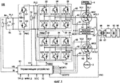
фиг.1 изображает блок-схему гибридного транспортного средства, представленного как пример транспортного средства с электрическим приводом, согласно изобретению;figure 1 depicts a block diagram of a hybrid vehicle, presented as an example of an electric vehicle, according to the invention;
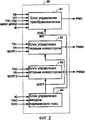
фиг.2 - функциональную блок-схему управляющего устройства, показанного на фиг.1, согласно изобретению;figure 2 is a functional block diagram of the control device shown in figure 1, according to the invention;
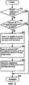
фиг.3 - диаграмму последовательности операций способа управления для выполнения зарядки устройства хранения электроэнергии устройством управления путем ввода переменного тока согласно изобретению;FIG. 3 is a flowchart of a control method for charging an electric power storage device by a control device by inputting alternating current according to the invention; FIG.
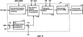
фиг.4 - функциональную блок-схему блока управления контроллером, показанным на фиг.2, согласно изобретению;figure 4 is a functional block diagram of a control unit of the controller shown in figure 2, according to the invention;
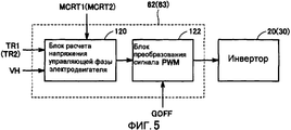
фиг.5 - функциональную блок-схему блоков управления первым и вторым инверторами, показанными на фиг.2, согласно изобретению;5 is a functional block diagram of the control units of the first and second inverters shown in figure 2, according to the invention;
фиг.6 - блок-схему гибридного транспортного средства согласно другому варианту выполнения изобретения.6 is a block diagram of a hybrid vehicle according to another embodiment of the invention.
Подробное описание предпочтительного варианта воплощения изобретенияDetailed Description of a Preferred Embodiment
На фиг.1 представлена блок-схема гибридного транспортного средства, представленного как пример транспортного средства с электрическим приводом согласно варианту воплощения настоящего изобретения. Гибридное транспортное средство 100 содержит устройство В хранения электроэнергии, повышающий преобразователь 10, инверторы 20 и 30, мотор-генераторы MG1 и MG2, двигатель 4 внутреннего сгорания, механизм 3 распределения мощности, колесо 2 и управляющее устройство 60.1 is a block diagram of a hybrid vehicle, shown as an example of an electric powered vehicle according to an embodiment of the present invention. The
Гибридное транспортное средство 100 также содержит входную клемму 90, выпрямитель 92, инвертор 94, трансформатор 86 и линии ACL1 и ACL2 переменного тока. Кроме того, гибридное транспортное средство 100 содержит линии PL1 и PL2 питания, линию SL заземления, конденсаторы С1 и С2, линии UL1-UL3 U-фазы, линии VL1-VL3 V-фазы, линии WL1-WL3 W-фазы, датчики 71, 72 и 74 напряжения и датчики 80, 82 и 84 тока.The
Механизм 3 распределения мощности соединен с двигателем 4 внутреннего сгорания и мотор-генераторами MG1 и MG2 для распределения мощности между ними. Например, в качестве механизма 3 распределения мощности можно использовать механизм планетарной зубчатой передачи, содержащий три вращающихся вала солнечной шестерни, планетарное водило и неподвижное зубчатое колесо. Три вращающихся вала соединены с каждым из вращающихся валов двигателя 4 внутреннего сгорания и мотор-генераторов MG1 и MG2. Например, пропустив коленчатый вал двигателя 4 внутреннего сгорания через центр пустотелого ротора мотор-генератора MG1, двигатель 4 внутреннего сгорания и мотор-генераторы MG1 и MG2 можно механически соединить с механизмом 3 распределения мощности.The power distribution mechanism 3 is connected to an internal combustion engine 4 and motor generators MG1 and MG2 for distributing power between them. For example, as a power distribution mechanism 3, a planetary gear mechanism may be used, comprising three rotating sun gear shafts, a planet carrier and a stationary gear. Three rotating shafts are connected to each of the rotating shafts of the internal combustion engine 4 and motor generators MG1 and MG2. For example, by passing the crankshaft of the internal combustion engine 4 through the center of the hollow rotor of the motor generator MG1, the internal combustion engine 4 and the motor generators MG1 and MG2 can be mechanically connected to the power distribution mechanism 3.
Вращающийся вал мотор-генератора MG2 соединен с колесом 2 через редуктор и/или приводящую оперативную передачу (не показаны). Кроме того, редуктор для вращающегося вала мотор-генератора MG2 может быть встроен в механизм 3 распределения мощности.The rotating shaft of the motor generator MG2 is connected to the
Мотор-генератор MG1 встроен в гибридное транспортное средство 100, работая как генератор мощности, приводимый в действие двигателем 4 внутреннего сгорания, и как электродвигатель, способный запускать двигатель 4 внутреннего сгорания. Мотор-генератор MG2 встроен в гибридное транспортное средство 100 как электродвигатель, приводящий в движение колесо 2, являющееся ведомым колесом.The motor generator MG1 is integrated in the
Устройство В хранения электроэнергии имеет положительный электрод, соединенный с линией PL1 питания, и отрицательный электрод, соединенный с линией SL заземления. Между линией PL1 питания и линией SL заземления подключен конденсатор С1.The electric power storage device B has a positive electrode connected to the power line PL1 and a negative electrode connected to the ground line SL. A capacitor C1 is connected between the power line PL1 and the ground line SL.
Повышающий преобразователь 10 содержит катушку L индуктивности n-p-n-транзисторы Q1 и Q2 и встречно-параллельные диоды D1 и D2. N-P-N-транзисторы Q1 и Q2 последовательно включены между линией PL2 питания и линией SL заземления. Встречно-параллельные диоды D1 и D2 включены между коллектором и эмиттером n-p-n-транзисторов Q1 и Q2 соответственно, чтобы проводить ток со стороны эмиттера на сторону коллектора. Один конец катушки L индуктивности соединен с точкой разветвления n-p-n-транзисторов Q1 и Q2, а другой конец соединен с линией питания PL1.
В качестве n-p-n-транзисторов, указанных выше и описанных ниже, можно использовать, например, биполярные транзисторы с изолированным затвором. Далее, вместо n-p-n-транзистора можно использовать силовой переключающий элемент, такой как мощный полевой МОП-транзистор (полевой транзистор со структурой металл-оксид-полупроводник).As the npn transistors mentioned above and described below, for example, insulated gate bipolar transistors can be used. Further, instead of an n-p-n-transistor, a power switching element such as a high-power MOSFET (metal-oxide-semiconductor field-effect transistor) can be used.
Между линией PL2 питания и линей SL заземления включен конденсатор С2. Инвертор 20 содержит ветвь 22 U-фазы, ветвь 24 V-фазы и ветвь 26 W-фазы. Ветвь 22 U-фазы, ветвь 24 V-фазы и ветвь 26 W-фазы соединены параллельно между линией PL2 питания и линией SL заземления. Ветвь 22 U-фазы образована n-p-n-транзисторами Q11 и Q12, включенными последовательно. Ветвь 24 V-фазы образована n-p-n-транзисторами Q13 и Q14, включенными последовательно. Ветвь 26 W-фазы образована n-p-n-транзисторами Q15 и Q16, включенными последовательно. Между коллектором и эмиттером n-p-n-транзисторов Q11-Q16 включены встречно-параллельные диоды D11-D16 соответственно, проводящие ток от стороны эмиттера к стороне коллектора.A capacitor C2 is connected between the power line PL2 and the ground line SL. The
Мотор-генератор VG1 содержит 3-фазную обмотку 12 статора. Обмотка U1 U-фазы, обмотка V1 V-фазы и обмотка W1 W-фазы, образующие 3-фазную обмотку 12, имеют первые концы, соединенные друг с другом для образования нейтральной точки N1, и вторые концы, соединенные с точками разветвления соответствующих n-p-n-транзисторов ветви 22 U-фазы, ветви 24 V-фазы и ветви 26 W-фазы инвертора 20.The motor generator VG1 contains a 3-phase stator winding 12. The U-phase winding U1, the V-phase winding V1, and the W-phase winding W1 forming a 3-phase winding 12 have first ends connected to each other to form a neutral point N1, and second ends connected to branch points of the corresponding npn- transistors of the
Инвертор 30 содержит ветвь 32 U-фазы, ветвь 34 V-фазы и ветвь 36 W-фазы. Мотор-генератор MG2 содержит 3-фазную обмотку 14 статора. Конфигурация инвертора 30 и мотор-генератора MG2 аналогична конфигурации инвертора 20 и мотор-генератора MG1 соответственно. The
Трансформатор 86 содержит первичную обмотку 87 и вторичную обмотку 88. Вторичная обмотка 88 соединена с нейтральными точками N1 и N2 3-фазных обмоток 12 и 14 мотор-генераторов MG1 и MG2 через линии ACL1 и ACL2 переменного тока соответственно. Первичная обмотка 87 соединена с инвертором 94. Выпрямитель 92 соединен с первичной стороной инвертора 94. Входная клемма 90 соединена с первичной стороной выпрямителя 92.The
Устройство В хранения электроэнергии является заряжаемым источником питания постоянного тока, например, вторичным никель-водородным или литий-ионным аккумулятором. Устройство В хранения электроэнергии подает питание постоянного тока на повышающий преобразователь 10. Устройство В хранения электроэнергии заряжается повышающим преобразователем 10. В качестве устройства В хранения электроэнергии можно использовать конденсатор большой емкости.The electric power storage device B is a rechargeable DC power source, for example, a secondary nickel-hydrogen or lithium-ion battery. The electric power storage device B supplies DC power to the
Датчик 71 напряжения определяет напряжение VB устройства В хранения электроэнергии для подачи обнаруженного напряжения VB на управляющее устройство 60. Датчик 84 тока определяет ток IB, входящий и выходящий из устройства В хранения электроэнергии, и подает обнаруженный ток на управляющее устройство 60. Конденсатор С1 сглаживает колебания напряжения между линией PL1 питания и линией SL заземления.The
Повышающий преобразователь 10 реагирует на сигнал PWC от управляющего устройства 60 на повышение напряжения постоянного тока от устройства В хранения электроэнергии, используя катушку L индуктивности и подает повышенное напряжение в линию PL2 питания. Более конкретно, на основании сигнала PWC от управляющего устройства 60, повышающий преобразователь 10 накапливает текущий ток в ответ на операцию переключения n-p-n-транзистора Q2 в форме энергии магнитного поля на катушке L индуктивности для повышения напряжения постоянного тока, выходящего из устройства В хранения электроэнергии. Повышающий преобразователь 10 выводит повышенное напряжение в линию PL2 питания через встречно-параллельный диод D1 в момент отключения n-p-n-транзистора Q2. Когда осуществляется зарядка устройства В хранения электроэнергии от коммерческого источника питания, являющегося внешним относительно транспортного средства и соединенного с входной клеммой 90, повышающий преобразователь 10 управляет током зарядки на устройстве В хранения электроэнергии на основе сигнала PWC от управляющего устройства 60.The
Конденсатор С2 сглаживает скачки напряжения между линией PL2 питания и линией SL заземления. Датчик 72 напряжения определяет напряжение на клеммах конденсатора С2, т.е. напряжение VH на линии PL2 питания относительно линии SL заземления и подает найденное напряжение VH на управляющее устройство 60.Capacitor C2 smoothes the power surges between the power line PL2 and the ground line SL. The
На основе сигнала PWM1 от управляющего устройства 60 инвертор 20 преобразует напряжение постоянного тока из линии PL2 питания в напряжение 3-фазного переменного тока, которое подается на мотор-генератор MG1. Соответственно мотор-генератор MG1 приводится во вращение для генерирования конкретного крутящего момента. Инвертор 20 преобразует напряжение 3-фазного переменного тока, генерируемого мотор-генератором MG1 после получения выходного сигнала двигателя 4 внутреннего сгорания, в напряжение постоянного тока на основании сигнала PWM1 от управляющего устройства 60 и выводит полученное напряжение постоянного тока в линию PL2 питания.Based on the signal PWM1 from the
На основании сигнала PWM2 от управляющего устройства 60 инвертор 30 преобразует напряжение постоянного тока, поступающее из линии PL2 питания в напряжение 3-фазного переменного тока, подаваемое на мотор-генератор MG2. Соответственно мотор-генератор MG2 приводится во вращение для генерирования заданного крутящего момента. В режиме регенеративного торможения транспортного средства инвертор 30 преобразует напряжение 3-фазного переменного тока, генерируемое мотор-генератором MG2 при получении вращающей силы от колеса 2, в напряжение постоянного тока, на основании сигнала PWM2 от управляющего устройства 60, и подает преобразованное напряжение постоянного тока в линию PL2 питания.Based on the signal PWM2 from the
В настоящем описании термин "регенеративное торможение" включает операцию торможения с регенеративным генерированием энергии, когда водитель транспортного средства нажимает педаль тормоза, или уменьшение скорости (или прекращение ускорения) транспортного средства во время регенеративного генерирования энергии путем прекращения нажатия педали акселератора при вождении, не нажимая педаль тормоза.As used herein, the term “regenerative braking” includes a regenerative energy generation braking operation when a vehicle driver depresses a brake pedal, or reducing a vehicle speed (or stopping acceleration) during regenerative energy generation by stopping the accelerator pedal while driving without depressing the pedal the brakes.
При зарядке устройства В хранения электроэнергии от коммерческого источника питания, подключенного к входной клемме 90, инверторы 20 и 30 выпрямляют напряжение переменного тока, повышаемого и направляемого на нейтральные точки N1 и N2 3-фазных обмоток 12 и 14 трансформатором 86 для подачи в линию PL2 питания. Когда устройство В хранения электроэнергии должно заряжаться от коммерческого источника питания, n-p-n-транзисторы Q11-Q16 и Q21-Q26 инверторов 20 и 30 отключаются (затвор перекрывается) и выпрямление осуществляется встречно-параллельными диодами D11-D16 и D21-D26.When charging the power storage device B from a commercial power source connected to input terminal 90,
Мотор-генераторы MG1 и MG2 являются 3-фазными электродвигателями переменного тока, например 3-фазными синхронными двигателями переменного тока. Мотор-генератор MG1 использует выход двигателя внутреннего сгорания 4 для генерирования напряжения 3-фазного переменного тока, которое подается на инвертор 20. Мотор-генератор MG1 генерирует приводную мощность под воздействием напряжения 3-фазного переменного тока, поступающего от инвертора 20, для пуска двигателя 4 внутреннего сгорания. Мотор-генератор MG2 генерирует тяговый момент транспортного средства под воздействием напряжения 3-фазного переменного тока, поступающего от инвертора 30. В режиме регенеративного торможения транспортного средства мотор-генератор MG2 генерирует и подает на инвертор 30 напряжение 3-фазного переменного тока.The motor generators MG1 and MG2 are 3-phase AC motors, for example 3-phase synchronous AC motors. The motor generator MG1 uses the output of the internal combustion engine 4 to generate a 3-phase AC voltage that is supplied to the
Трансформатор 86 повышает напряжение переменного тока высокой частоты от инвертора 94 до уровня, превышающего напряжение VB устройства В хранения энергии и выводит это повышенное напряжение в линии переменного тока ACL1 и ACL2. Трансформатор 86 изолирует соответствующие элементы, такие как инверторы 20 и 30, встроенные в транспортное средство, от коммерческого источника питания, подключенного к входной клемме 90. Датчик 74 напряжения определяет напряжение VAC между линиями ACL1 и ACL2 и подает измеренное напряжение VAC на управляющее устройство 60.
Входная клемма 90 служит для приема коммерческого напряжения переменного тока, когда устройство В хранения электроэнергии необходимо зарядить от коммерческого источника питания, являющегося внешним относительно транспортного средства. Выпрямитель 92 выпрямляет коммерческое напряжение переменного тока, подаваемое на клемму 90 для вывода его на инвертор 94. Инвертор 94 преобразует напряжение постоянного тока, полученное от выпрямителя 92, в напряжение переменного тока высокой частоты, которое выводится на первичную обмотку 87 трансформатора 86.The
Причина, по которой частоту коммерческого напряжения переменного тока от коммерческого источника питания повышают выпрямителем 92 и инвертором 94, состоит в том, что работа трансформатора 86 на более высокой частоте позволяет уменьшить его габариты.The reason that the frequency of the commercial AC voltage from the commercial power source is increased by the
Датчик 80 тока определяет ток MCRT1, текущий на мотор-генератор MG1, и выводит найденный ток MCRT1 на управляющее устройство 60. Датчик 82 тока определяет ток MCRT2, текущий на мотор-генератор MG2, и выводит найденный ток MCRT2 на управляющее устройство 60.The
Управляющее устройство 60 генерирует сигнал PWC для привода повышающего преобразователя 10 и сигналы PWM1 и PWM2 для привода инверторов 20 и 30 соответственно. Генерируемые сигналы PWC, PWM1 и PWM2 выводятся на повышающий преобразователь 10, инвертор 20 и инвертор 30 соответственно. The
Управляющее устройство 60 определяет, заряжать ли устройство В хранения электроэнергии от коммерческого источника питания, соединенного с клеммой 90, и когда осуществляется зарядка, отключает все n-p-n-транзисторы Q11-Q16 и Q21-Q26 инверторов 20 и 30 и осуществляет управление зарядкой устройства В хранения электроэнергии посредством повышающего преобразователя 10.The
На фиг.2 представлена функциональная блок-схема управляющего устройства 60. Управляющее устройство 60 содержит блок 61 управления преобразователем, первый блок 62 управления инвертором, второй блок 63 управления инвертором и блок 64 управления вводом переменного тока.2 is a functional block diagram of a
На основании напряжения VB, полученного от датчика 71 напряжения, напряжения VH от датчика 72 напряжения, величин команд крутящего момента TR1 и TR2, а также сигналов MNR1 и MNR2 частоты вращения мотор-генераторов MG1 и MG2, вводимых от HV-ECU (не показан; то же относится и нижеследующему описанию), тока IB от датчика тока 84 и уставки IBR тока зарядки и команды CHG управления зарядкой от блока 64 управления вводом переменного тока, блок 61 управления преобразователем генерирует сигнал PWC для включения/выключения n-p-n-транзисторов Q1 и Q2 повышающего преобразователя 10 для подачи сгенерированного сигнала PWC на повышающий преобразователь 10.Based on the voltage VB received from the
На основе величины команды TR1 крутящего момента и тока MCRT1 мотор-генератора MG1 и напряжения VH первый блок 62 управления инвертором генерирует сигнал PWM1 для включения/выключения n-p-n-транзисторов Q11-Q16 инвертора 20 для подачи сгенерированного сигнала PWM1 на инвертор 20. По получении команды GOFF на отключение затвора от блока 64 управления вводом переменного тока первый блок 62 управления инвертором генерирует и подает на инвертор 20 сигнал PWM1 для отключения всех n-p-n-транзисторов Q11-Q16 инвертора 20.Based on the magnitude of the torque command TR1 and current MCRT1 of motor generator MG1 and voltage VH, the first
На основе величины команды TR2 крутящего момента и тока MCRT2 мотор-генератора MG2 и напряжения VH второй блок 63 управления инвертором генерирует сигнал PWM2 для включения/выключения n-p-n-транзисторов Q21-Q26 инвертора 30. Сгенерированный сигнал PWM2 подается на инвертор 30. По получении команды GOFF на отключение затвора от блока 64 управления вводом переменного тока второй блок 63 управления инвертором генерирует и подает на инвертор 30 сигнал PWM2 для отключения всех n-p-n-транзисторов Q21-Q26 инвертора 30.Based on the magnitude of the torque command TR2 and current MCRT2 of motor generator MG2 and voltage VH, the second
На основании сигнала IG от замка зажигания (не показан) (или выключателя зажигания; то же относится и к нижеследующему описанию) и напряжения VAC от датчика 74 напряжения блок 64 управления вводом переменного тока определяет, выполнять ли зарядку устройства В хранения электроэнергии от коммерческого источника питания, являющегося внешним относительно транспортного средства. Во время проведения зарядки устройства В хранения электроэнергии блок 64 управления вводом переменного тока выдает команду GOFF на закрывание затворов на блоки 62 и 63 управления первым и вторым инверторами и выдает команду CHG управления зарядкой на блок 61 управления преобразователем. Команда CHG управления зарядкой является инструкцией блоку 61 управления преобразователем на осуществление управления зарядкой устройства В хранения электроэнергии.Based on the IG signal from the ignition switch (not shown) (or the ignition switch; the same applies to the following description) and the VAC voltage from the
Когда выполняется зарядка устройства В хранения электроэнергии, блок 64 управления вводом переменного тока рассчитывает уставку IBR тока зарядки устройства В хранения электроэнергии на основании состоянии заряда (SOC) этого устройства, полученного от HV-ECU, и выдает рассчитанную уставку IBR тока зарядки на блок 61 управления преобразователем. Состояние зарядки SOC устройства В хранения электроэнергии рассчитывается на основе хорошо известной схемы ECU (электронным блоком управления) аккумулятора (не показан).When charging the power storage device B, the AC
На фиг.3 представлена диаграмма последовательности операций способа управления, предназначенного для выполнения зарядки устройства В хранения электроэнергии блоком 64 управления вводом переменного тока (фиг.2). Процесс по этой диаграмме вызывается и выполняется из главной программы с постоянными интервалами или каждый раз, когда возникает заранее определенное состояние.FIG. 3 is a flowchart of a control method for charging an electric power storage device B by an AC input control unit 64 (FIG. 2). The process in this diagram is called and executed from the main program at regular intervals or every time a predetermined state occurs.
Блок 64 (фиг.3) управления вводом переменного тока определяет, был ли повернут замок зажигания в положение ВЫКЛ (OFF) на основании сигнала IG от замка зажигания (шаг S10). Определив, что замок зажигания не находится в положении ВЫКЛ (НЕТ на шаге S10), блок 64 управления вводом переменного тока определяет, что нельзя соединять коммерческий источник питания с вводной клеммой 90 для зарядки устройства В хранения электроэнергии, и управление переходит на шаг S60. Управление возвращается в главную программу.The AC input control unit 64 (FIG. 3) determines whether the ignition switch has been turned to the OFF position based on the signal IG from the ignition switch (step S10). Having determined that the ignition switch is not in the OFF position (NO in step S10), the AC
Когда на шаге S10 будет определено, что замок зажигания находится в положении ВЫКЛ, (ДА на шаге S10), блок 64 управления вводом переменного тока на основе напряжения VAC от датчика напряжения 74 на шаге S20 определяет, подано ли коммерческое напряжение переменного тока от коммерческого источника питания на клемму 90. Если это напряжение не подано (НЕТ на шаге S20), блок 64 управления вводом переменного тока не осуществляет процесс зарядки и управление переходит на шаг S60. Таким образом, управление возвращается в главную программу.When it is determined in step S10 that the ignition switch is in the OFF position (YES in step S10), the AC
Когда подача коммерческого напряжения переменного тока на входную клемму 90 подтверждается (ДА на шаге S20), блок 64 управления вводом переменного тока рассчитывает величину уставки IBR тока зарядки на устройстве В хранения электроэнергии на основании состояния SOC заряда этого устройства. Рассчитанная величина уставки IBR тока зарядки выводится на блок 61 управления преобразователем (шаг S30). Например, если состояние заряда устройства В хранения электроэнергии ниже, чем опорная величина, соответствующая достаточному состоянию заряда устройства В хранения электроэнергии, блок 64 управления вводом переменного тока задает заранее определенную величину уставки IBR тока зарядки устройства В хранения электроэнергии. Величина уставки IBR тока зарядки может меняться в зависимости от состояния заряда устройства В хранения электроэнергии.When the supply of commercial AC voltage to the
После того как на шаге S30 был задан ток зарядки устройства В хранения электроэнергии, блок 64 управления вводом переменного тока выводит команду на GOFF закрывание затворов на блоки 62, 63 управления первым и вторым инверторами (шаг S40). В ответ блоки 62 и 63 управления первым и вторым инверторами выключают все n-p-n-транзисторы Q11-Q16 и Q21-Q26 в инверторах 20 и 30 соответственно. Переключение инверторов 20 и 30 прерывается на время зарядки устройства В хранения электроэнергии от коммерческого источника энергии, соединенного с вводной клеммой 90.After the charging current of the electric power storage device B has been set in step S30, the AC
После процесса по шагу S40 блок 64 управления вводом переменного тока выдает команду CHG управления зарядкой на блок 61 управления преобразователем, которая является инструкцией на выполнение управления зарядкой устройства В хранения электроэнергии (шаг S50). Соответственно блок 61 управления преобразователем осуществляет управление зарядкой устройства В хранения электроэнергии, как будет описано ниже. Во время зарядки повышающий преобразователь 10 заряжает устройство В хранения электроэнергии, управляя током зарядки, поддерживая его на уровне уставки IBR тока зарядки. Затем управление переходит на главную программу (шаг S60).After the process in step S40, the AC
На фиг.4 показана функциональная блок-схема блока 61 управления преобразователем на фиг.2. Блок 61 управления преобразователем содержит блок 111 расчета входного напряжения инвертора, блоки 112 и 114 вычитания, блок 113 пропорционально-интегрального регулирования (PI), блок 115 расчета команды обратной связи по напряжению, блок 116 расчета продолжительности включения и блок 117 преобразования сигнала PWM.FIG. 4 shows a functional block diagram of the
Блок 111 расчета входного напряжения инвертора рассчитывает оптимальную величину (уставку) входного напряжения инвертора, т.е. команду VH_com напряжения, на основе величин команд TR1 и TR2 крутящего момента и команд MRN1 и MRN2 частоты вращения двигателей от HV-ECU. Вычисленная команда VH_com напряжения подается на блок 115 расчета команды обратной связи по напряжению.The inverter input
Блок 112 вычитания получает уставку IBR тока зарядки от блока 64 управления вводом постоянного тока и величину тока IB от датчика 84 тока и вычитает величину тока IB из величины уставки IBR. Результат вычитания выводится на блок 113 пропорционально-интегрального регулирования.The
Блок 113 пропорционально-интегрального регулирования выполняет операцию пропорционального и интегрального регулирования отклонения между уставкой IBR и током IB, полученным на входе от блока 112 вычитания. Вычисленный результат подается на блок 114 вычитания.The proportional-
Блок 114 вычитания получает величину, выводимую блоком 113 пропорционально-интегрального регулирования и величину напряжения VH от датчика 72 напряжения для вычитания выходной величины, выводимой блоком 113 пропорционально-интегрального регулирования из величины напряжения VH. Полученный результат выводится на блок 115 расчета команды обратной связи по напряжению в форме команды VH_IB напряжения.The
Блок 115 расчета команды обратной связи по напряжению получает величину напряжения VH, команду CHG управления зарядом от блока 64 управления вводом переменного тока, команду VH_com напряжения от блока 111 расчета команды входного напряжения инвертора и команду VH_IB напряжения от блока 114 вычитания. Когда команда CHG управления зарядом не активна, блок 115 расчета команды обратной связи по напряжению рассчитывает команду VH_fb обратной связи по напряжению для управления напряжением VH на уровне команды VH_com, на основании напряжения VH и команды VH_com напряжения от блока 111 расчета команды входного напряжения инвертора. Рассчитанная команда VH_fb обратной связи по напряжению выводится на блок 116 расчета продолжительности включения.The voltage feedback
Когда команда CHG управления зарядом активна, блок 115 расчета команды обратной связи по напряжению рассчитывает команду VH_fb обратной связи по напряжению для управления напряжением VH на уровне команды VH_IB напряжения, на основании напряжения VH и команды VH_IB напряжения, поступающей от блока 114 вычитания. Рассчитанная команда VH_fb обратной связи по напряжению выводится на блок 116 расчета продолжительности включения.When the charge control command CHG is active, the voltage feedback
На основании величины напряжения VB, получаемой от датчика 71 напряжения и команды VH_fb обратной связи по напряжению, получаемой от блока 115 расчета команды обратной связи по напряжению, блок 116 расчета продолжительности включения рассчитывает продолжительность включения для управления напряжением VH на уровне команды VH_com или VH_IB напряжения. Рассчитанная продолжительность включения выводится на блок 117 преобразования сигнала PWM.Based on the magnitude of the voltage VB received from the
На основании величины продолжительности включения, полученной от блока 116 расчета продолжительности включения, блок 117 преобразования сигнала PWM генерирует сигнал PWM (широтно-импульсной модуляции) для включения/выключения n-p-n-транзисторов Q1 и Q2 повышающего преобразователя 10. Этот сгенерированный сигнал PWM выводится на n-p-n-транзисторы Q1 и Q2 повышающего преобразователя 10.Based on the on-time duration obtained from the on-time
Когда команда CHG управления зарядкой от блока 64 управления вводом переменного тока не активна, т.е. когда зарядка устройства В хранения электроэнергии от коммерческого источника питания не осуществляется, блок 61 управления преобразователем управляет продолжительностью включения верхней ветви и нижней ветви повышающего преобразователя 10 так, что напряжение VH регулируется на уровне команды VH_com напряжения, рассчитанной блоком 111 расчета команды входного напряжения инвертора.When the charge control command CHG from the AC
В отличие от того, когда команда CHG управления зарядкой от блока 64 управления вводом переменного тока активна, т.е. выполняется зарядка устройства В хранения электроэнергии от коммерческого источника питания, продолжительность включения верхней ветви и нижней ветви повышающего преобразователя 10 регулируется так, что ток IB зарядки устройства В хранения электроэнергии задается на уровне уставки IBR тока зарядки.In contrast to when the charge control command CHG from the AC
На фиг.5 представлена функциональная блок-схема блоков 62 и 63 управления первым и вторым инверторами на фиг.2. Блоки 62 и 63 управления первым и вторым инверторами содержат блок 120 расчета напряжения фазы для управления двигателем и блок 122 преобразования сигнала PWM.Figure 5 presents a functional block diagram of
Блок 120 расчета напряжения фазы управления двигателем получает от датчика 72 напряжение VH, т.е. входное напряжение инверторов 20 и 30, получает от датчика 80 (или 82) величину MCRT1 (или MCRT2) тока на двигателе, текущего через каждую фазу мотор-генератора MG1 (или MG2), и получает от HV-ECU величину TR1 (или TR2) команды крутящего момента. На основании этих введенных величин блок 120 расчета напряжения фазы управления двигателем рассчитывает напряжение, подаваемое на обмотку каждой фазы мотор-генератора MG1 (или MG2). Рассчитанное напряжение для обмотки каждой фазы выводится на блок 122 преобразования сигнала PWM.The engine control phase
Когда команда GOFF на закрывание затворов от блока 64 управления вводом переменного тока не активна, блок 122 преобразования сигнала PWM реагирует на команду напряжения обмотки каждой фазы, полученную от блока 120 расчета напряжения фазы управления двигателем, генерируя сигнал PWM1_0 (один тип сигнала PWM1) (или сигнал PWM2_0) (один тип сигнала PWM2), который включает/выключает каждый из n-p-n-транзисторов Q11-Q16 (или Q21-Q26) инвертора 20 (или 30). Сгенерированный сигнал PWM1_0 (или PWM2_0) выводится на каждый из n-p-n-транзисторов Q11-Q16 (или Q21-Q26) инвертора 20 (или 30).When the GOFF command to close the gates from the AC
Таким образом, осуществляется управление переключением каждого из n-p-n-транзисторов Q11-Q16 (или Q21-Q26) и ток, проходящий на каждую фазу мотор-генератора MG1 (или MG2), регулируется так, чтобы мотор-генератор MG1 (или MG2) выдавал конкретный крутящий момент. В результате, создается крутящий момент, соответствующий величине команды TR1 (или TR2) крутящего момента.Thus, the switching control of each of the npn transistors Q11-Q16 (or Q21-Q26) is carried out and the current passing to each phase of the motor generator MG1 (or MG2) is controlled so that the motor generator MG1 (or MG2) produces a specific torque. As a result, a torque corresponding to the value of the torque command TR1 (or TR2) is created.
Когда команда GOFF на закрывание затворов от блока 64 управления вводом переменного тока активна, блок 122 преобразования сигнала PWM генерирует сигнал PWM1_1 (один тип сигнала PWM1) (или сигнал PWM2_1 (один тип сигнала PWM2)), который отключает все n-p-n-транзисторы Q11-Q16 (или Q21-Q26) инвертора 20 (или 30), независимо от выхода блока 120 расчета напряжения фазы управления двигателем. Сгенерированный сигнал PWM1_1 (или PWM2_1) выводится на n-p-n-транзисторы Q11-Q16 (или Q21-Q26) инвертора 20 (или 30).When the GOFF shutter command from the AC
Ниже приведено описание работы гибридного транспортного средства 100 (фиг.1) в целом. Гибридное транспортное средство 100 движется, используя в качестве источника мощности двигатель 4 внутреннего сгорания и мотор-генератор MG2. Электроэнергия генерируется мотор-генератором MG1, приводимым двигателем 4 внутреннего сгорания, для подачи электроэнергии на устройство В хранения электроэнергии. В режиме регенеративного торможения транспортного средства происходит регенерация энергии мотор-генератором MG2, использующим силу своего вращения, и эта энергия подается на устройство В хранения электроэнергии.The following is a description of the operation of the hybrid vehicle 100 (FIG. 1) as a whole. The
В гибридном транспортном средстве 100 устройство В хранения электроэнергии можно заряжать, используя коммерческий источник питания, соединенный с входной клеммой 90. Коммерческое напряжение переменного тока, поданное на входную клемму 90, преобразуется в переменный ток высокой частоты выпрямителем 92 и инвертором 94, который подается на трансформатор 86.In
Трансформатор 86 повышает напряжение переменного тока высокой частоты, поступающее от инвертора 94, до уровня, превышающего напряжение VB на устройстве В хранения электроэнергии. Повышенное напряжение переменного тока выводится на нейтральные точки N1 и N2 3-фазных обмоток 12 и 14 мотор-генераторов MG1 и MG2 по линиям ACL1 и ACL2 переменного тока. Переменное напряжение, поданное на нейтральные точки N1 и N2, выпрямляется инверторами 20 и 30 для вывода в линию PL2 источника питания.
Когда происходит зарядка устройства В хранения электроэнергии от коммерческого источника питания, каждый из n-p-n-транзисторов Q11-Q16 и Q21-Q26 инверторов 20 и 30 выключен и не осуществляет переключение. Поскольку напряжение переменного тока, поданное на нейтральные точки N1 и N2, повышено трансформатором 86 до уровня, превышающего напряжение VB устройства В хранения электроэнергии, встречно-параллельные диоды D11-D16 и D21-D26 инверторов 20 и 30 работают как выпрямляющие цепи для выпрямления переменного напряжения, поданного на нейтральные точки N1 и N2 для вывода в линию PL2 источника питания.When charging the power storage device B from a commercial power source, each of the npn transistors Q11-Q16 and Q21-Q26 of the
Управляющее устройство 60 задает ток зарядки устройства В хранения электроэнергии на основе состояния заряда этого устройства В. Повышающий преобразователь 10 реагирует на сигнал PWC от управляющего устройства 60 для зарядки устройства В хранения электроэнергии, управляя током зарядки из линии PL2 источника питания на устройство В хранения электроэнергии.The
Согласно описываемому варианту подача напряжения переменного тока от коммерческого источника питания, являющегося внешним относительно транспортного средства, на нейтральные точки N1 и N2 3-фазных обмоток 12 и 14 мотор-генераторов MG1 и MG2 позволяет заряжать устройство В хранения электроэнергии без необходимости в дополнительном специализированном преобразователе переменного тока в постоянный.According to the described embodiment, applying AC voltage from a commercial power source that is external to the vehicle to the neutral points N1 and N2 of the 3-
Поскольку между входной клеммой 90 и нейтральными точками N1 и N2 имеется трансформатор 86, коммерческое напряжение переменного тока от коммерческого источника питания повышается до уровня, превышающего уровень напряжения VB устройства В хранения электроэнергии, которое должно быть подано на нейтральные точки N1 и N2, при этом когда устройство В хранения электроэнергии заряжается от коммерческого источника питания, переключения инверторов 20 и 30 не требуется. Следовательно, потери на переключение на инверторах 20 и 30 можно устранить, что приводит к уменьшению потерь при зарядке. Можно также обеспечить изоляцию устройств, таких как мотор-генераторы MG1 и MG2 и инверторы 20 и 30 от коммерческого источника питания.Since there is a
Путь от входной клеммы 90 до первичной обмотки 87 трансформатора 86 может быть проложен вне гибридного транспортного средства.The path from the
На фиг.6 представлена полная блок-схема гибридного транспортного средства согласно модифицированному варианту воплощения настоящего изобретения. Гибридное транспортное средство 100А содержит вторичную обмотку 88 трансформатора 86. Первичная обмотка 87 трансформатора 86, входная клемма 90, выпрямитель 92 и инвертор 94 расположены вне гибридного транспортного средства.6 is a complete block diagram of a hybrid vehicle according to a modified embodiment of the present invention. Hybrid vehicle 100A comprises a secondary winding 88 of
Первичная обмотка 87 трансформатора 86, входная клемма 90, выпрямитель 92 и инвертор 94 выполнены как внешнее зарядное устройство. Когда необходимо зарядить устройство В хранения электроэнергии от коммерческого источника электроэнергии, соединенного с входной клеммой 90, первичную обмотку 87 подводят ко вторичной обмотке 88, встроенной в гибридное транспортное средство 100А, чтобы получить возможность повысить коммерческое напряжение переменного тока от коммерческого источника для подачи на нейтральные точки N1 и N2.The primary winding 87 of the
В гибридном транспортном средстве 100А зарядка устройства В хранения электроэнергии от коммерческого источника питания может проводиться бесконтактным способом. Кроме того, поскольку первичная катушка 87 трансформатора 86, входная клемма 90, выпрямитель 92 и инвертор 94 расположены вне транспортного средства, масса гибридного транспортного средства 100А может быть уменьшена по сравнению с гибридным транспортным средством 100, описанным выше.In the hybrid vehicle 100A, charging of the power storage device B from a commercial power source may be conducted in a non-contact manner. In addition, since the
Хотя описанный выше вариант между входной клеммой 90 и трансформатором 86 содержит выпрямитель 92 и инвертор 94, что позволяет уменьшить размеры трансформатора 86, настоящее изобретение также применимо и в том случае, если выпрямитель 92 и инвертор 94 отсутствуют.Although the above-described embodiment between the
Хотя в качестве примера транспортного средства с электроприводом согласно настоящему изобретению было описано гибридное транспортное средство, настоящее изобретение также применимо и к электрическому транспортному средству и к транспортному средству на топливных элементах, в которое помимо топливного элемента встроено устройство для хранения электроэнергии, такое как аккумулятор или конденсатор.Although a hybrid vehicle has been described as an example of an electric vehicle according to the present invention, the present invention is also applicable to an electric vehicle and a fuel cell vehicle in which, in addition to the fuel cell, an electric power storage device such as a battery or a capacitor is integrated .
В приведенном выше описании 3-фазные обмотки 12 и 14 соответствуют "первой многофазной обмотке" и "второй многофазной обмотке" соответственно. Инверторы 20 и 30 соответствуют "первому инвертору" и "второму инвертору" соответственно. Повышающий преобразователь 10 и трансформатор 86 соответствуют "преобразователю" и "повышающему устройству" соответственно. Мотор-генераторы MG1 и MG2 соответствуют "первому электродвигателю" и "второму электродвигателю" соответственно. In the above description, the 3-
Следует понимать, что описанные выше варианты являются иллюстративными и не ограничивают заявленное изобретение. Объем настоящего изобретения определен прилагаемой формулой изобретения и включает любые модификации, входящие в изобретательскую идею, объем которой определен приложенной формулой.It should be understood that the above options are illustrative and do not limit the claimed invention. The scope of the present invention is defined by the attached claims and includes any modifications that are included in the inventive idea, the scope of which is defined by the attached claims.
Claims (9)
преобразователь, установленный между каждым из первого и второго инверторов и устройством хранения электроэнергии, повышающее устройство, расположенное между первой нейтральной точкой первой многофазной обмотки и второй нейтральной точкой второй многофазной обмотки и источником питания, являющимся внешним относительно транспортного средства, и предназначенное для повышения напряжения, подаваемого от источника питания до уровня, превышающего напряжение на устройстве хранения электроэнергии, для подачи повышенного напряжения на первую и вторую нейтральные точки, при этом во время зарядки устройства хранения электроэнергии от источника питания первый и второй инверторы предназначены для вывода напряжения, повышенного и поданного на первую и вторую нейтральные точки повышающим устройством, на преобразователь через встречно-параллельный диод, при этом преобразователь получает выходное напряжение от первого и второго инверторов для зарядки устройства хранения электроэнергии.5. An electric powered vehicle containing an electric energy storage device, a first electric motor comprising a first multiphase winding connected by a star and being a stator winding, a second electric motor containing a second multiphase winding connected by a star and being a stator winding, the first and second inverters for the first and second electric motors, respectively, containing an anti-parallel diode connected in parallel to each switching element,
a converter installed between each of the first and second inverters and an electric power storage device, a boosting device located between the first neutral point of the first multiphase winding and the second neutral point of the second multiphase winding and a power source that is external to the vehicle and designed to increase the voltage supplied from a power source to a level exceeding the voltage at the electric power storage device for supplying an increased voltage to I tear up and the second neutral points, while during charging the electric power storage device from the power source, the first and second inverters are designed to output the voltage increased and applied to the first and second neutral points by the boosting device to the converter via an on-parallel diode, while the converter receives output voltage from the first and second inverters for charging the electric power storage device.
Applications Claiming Priority (2)
| Application Number | Priority Date | Filing Date | Title |
|---|---|---|---|
| JP2005253841A JP4367391B2 (en) | 2005-09-01 | 2005-09-01 | Charge control device and electric vehicle |
| JP2005-253841 | 2005-09-01 |
Publications (1)
| Publication Number | Publication Date |
|---|---|
| RU2354026C1 true RU2354026C1 (en) | 2009-04-27 |
Family
ID=37809020
Family Applications (1)
| Application Number | Title | Priority Date | Filing Date |
|---|---|---|---|
| RU2008112312/09A RU2354026C1 (en) | 2005-09-01 | 2006-08-30 | Charge control device and electrically powered vehicle |
Country Status (8)
| Country | Link |
|---|---|
| US (1) | US8054025B2 (en) |
| EP (1) | EP1936775A4 (en) |
| JP (1) | JP4367391B2 (en) |
| KR (1) | KR100933326B1 (en) |
| CN (1) | CN101253666B (en) |
| BR (1) | BRPI0615275A2 (en) |
| RU (1) | RU2354026C1 (en) |
| WO (1) | WO2007026942A1 (en) |
Cited By (10)
| Publication number | Priority date | Publication date | Assignee | Title |
|---|---|---|---|---|
| WO2013122703A1 (en) * | 2012-02-14 | 2013-08-22 | Ut-Battelle, Llc | Wireless power charging using point of load controlled high frequency power converters |
| RU2501144C2 (en) * | 2009-07-14 | 2013-12-10 | Кондуктикс-Вампфлер Гмбх | Device for inductive power transmission |
| RU2534017C1 (en) * | 2010-11-05 | 2014-11-27 | Тойота Дзидося Кабусики Кайся | Power supply system for vehicle and vehicle containing same system |
| RU2548367C2 (en) * | 2009-07-13 | 2015-04-20 | Конинклейке Филипс Электроникс Н.В. | Energy inductive transmission |
| RU2557785C1 (en) * | 2011-05-27 | 2015-07-27 | Ниссан Мотор Ко., Лтд. | Non-contact power supply device |
| RU2568606C2 (en) * | 2011-06-03 | 2015-11-20 | Тойота Дзидося Кабусики Кайся | Power contactless receiver and vehicle equipped therewith, power contactless transmitter and power contactless transmission system |
| RU2587152C2 (en) * | 2011-04-14 | 2016-06-10 | Рено С.А.С. | Battery charging device of vehicle power supply from single-phase network and device control method |
| RU2596613C2 (en) * | 2012-02-22 | 2016-09-10 | Тойота Дзидося Кабусики Кайся | Contactless power transmission, power receiving device and system for contactless power transmission |
| RU2624259C2 (en) * | 2012-04-27 | 2017-07-03 | Рено С.А.С. | Battery charging control method |
| RU2678318C1 (en) * | 2016-08-17 | 2019-01-28 | СиЭрЭрСи ЦИНДАО СЫФАН РОЛЛИН СТОК РИСЁРЧ ИНСТИТЬЮТ КО., ЛТД. | Management system and method of managing a charger device on the basis of a bridge converter with a phase shift |
Families Citing this family (40)
| Publication number | Priority date | Publication date | Assignee | Title |
|---|---|---|---|---|
| JP4325637B2 (en) * | 2006-04-24 | 2009-09-02 | トヨタ自動車株式会社 | Load driving device and vehicle equipped with the same |
| JP2008252990A (en) * | 2007-03-29 | 2008-10-16 | Toyota Motor Corp | Controller and control method of vehicle |
| WO2009028520A1 (en) | 2007-08-24 | 2009-03-05 | Toyota Jidosha Kabushiki Kaisha | Vehicle |
| JP4483911B2 (en) * | 2007-08-31 | 2010-06-16 | 株式会社デンソー | Rotating electric machine for vehicles |
| JP5160934B2 (en) * | 2008-03-28 | 2013-03-13 | 新電元工業株式会社 | Battery charging device and battery charging control method |
| JP4969547B2 (en) * | 2008-10-14 | 2012-07-04 | トヨタ自動車株式会社 | Control device and charge control method |
| US8080973B2 (en) | 2008-10-22 | 2011-12-20 | General Electric Company | Apparatus for energy transfer using converter and method of manufacturing same |
| JP2010239853A (en) * | 2009-03-12 | 2010-10-21 | Tetsuo Sekiya | Non-contact charger for electric vehicle |
| US9614389B2 (en) * | 2009-04-14 | 2017-04-04 | Ford Global Technologies, Llc | Method and system for controlling current flow through a power distribution circuit |
| DE102009021797B4 (en) * | 2009-05-18 | 2015-04-23 | Sew-Eurodrive Gmbh & Co Kg | Vehicle with charging arrangement for an energy storage of the vehicle |
| US8030884B2 (en) * | 2009-08-31 | 2011-10-04 | General Electric Company | Apparatus for transferring energy using onboard power electronics and method of manufacturing same |
| US9132741B2 (en) * | 2009-10-08 | 2015-09-15 | Ford Global Technologies, Llc | Method and system for controlling current flow through a power distribution circuit |
| KR101004498B1 (en) * | 2010-01-25 | 2010-12-31 | 엘에스산전 주식회사 | Charger |
| US8855951B2 (en) * | 2010-04-13 | 2014-10-07 | Ford Global Technologies, Llc | Power distribution circuit diagnostic system and method |
| JP5234050B2 (en) * | 2010-04-27 | 2013-07-10 | 株式会社デンソー | Vehicle power supply |
| US20110302078A1 (en) | 2010-06-02 | 2011-12-08 | Bryan Marc Failing | Managing an energy transfer between a vehicle and an energy transfer system |
| JP2012065396A (en) * | 2010-09-14 | 2012-03-29 | Yanmar Co Ltd | Electrically-driven work machine |
| JP5742850B2 (en) | 2010-10-19 | 2015-07-01 | 日産自動車株式会社 | Rotating electrical machine system |
| US9290097B2 (en) * | 2010-11-05 | 2016-03-22 | Robert Louis Steigerwald | Apparatus for transferring energy using onboard power electronics with high-frequency transformer isolation and method of manufacturing same |
| DE102010054848A1 (en) * | 2010-12-16 | 2012-06-21 | Conductix-Wampfler Ag | Device for inductive transmission of electrical energy |
| JP5947528B2 (en) * | 2011-11-30 | 2016-07-06 | 国立大学法人埼玉大学 | Vehicle drive device, vehicle, and non-contact charging system |
| KR20120116722A (en) * | 2011-04-13 | 2012-10-23 | 엘지전자 주식회사 | Electric vehicle and operating method of the same |
| FR2975843B1 (en) * | 2011-05-23 | 2013-05-17 | Renault Sa | METHOD FOR CONTROLLING THE SWITCHES OF A CURRENT RECTIFIER CONNECTED TO AN ONBOARD CHARGER. |
| US9007020B2 (en) * | 2011-05-25 | 2015-04-14 | Green Charge Networks | Charging service vehicles with battery and generator sources |
| WO2012164643A1 (en) * | 2011-05-27 | 2012-12-06 | トヨタ自動車株式会社 | Power source system, vehicle comprising power source system, and method for controlling power source system |
| KR101249962B1 (en) * | 2011-05-31 | 2013-04-09 | 국민대학교산학협력단 | Electric motor drive and regenerative braking control apparatus |
| KR101284331B1 (en) | 2011-12-09 | 2013-07-08 | 성균관대학교산학협력단 | Recharge systen for green car and method thereof |
| EP2634885B1 (en) | 2012-02-29 | 2015-09-02 | ABB Technology Ltd | A DC-power system with system protection capabilities |
| CN103847530B (en) | 2012-12-03 | 2017-04-12 | 通用电气公司 | Electric drive system and energy managing method thereof |
| KR101568225B1 (en) | 2013-02-06 | 2016-07-20 | 엘지전자 주식회사 | charging apparatus and electric vehicle including the same |
| JP6193681B2 (en) * | 2013-08-30 | 2017-09-06 | ヤンマー株式会社 | Engine generator |
| CN103701182A (en) * | 2013-12-16 | 2014-04-02 | 小米科技有限责任公司 | Charger, electronic equipment and charging system |
| NO337360B1 (en) * | 2014-03-11 | 2016-03-29 | Zaptec Ip As | Power supply system for charging electric vehicles |
| JP6372425B2 (en) * | 2015-06-09 | 2018-08-15 | 株式会社豊田自動織機 | AC power supply circuit |
| DE102016201444B4 (en) * | 2016-02-01 | 2018-11-15 | Continental Automotive Gmbh | DC-DC converter arrangement for an electrical machine |
| KR20180094327A (en) * | 2017-02-15 | 2018-08-23 | 주식회사 만도 | Control apparatus for electric power steering system and control method thereof |
| JP6693446B2 (en) * | 2017-03-10 | 2020-05-13 | トヨタ自動車株式会社 | Drive |
| EP3916989A4 (en) * | 2019-01-24 | 2022-09-07 | Hitachi Industrial Equipment Systems Co., Ltd. | Power conversion system |
| EP3866295A1 (en) * | 2020-02-13 | 2021-08-18 | Ningbo Geely Automobile Research & Development Co. Ltd. | A vehicle electrical system |
| CN112744101B (en) * | 2020-12-25 | 2023-02-17 | 中国第一汽车股份有限公司 | Charging and discharging control system and method and vehicle |
Family Cites Families (23)
| Publication number | Priority date | Publication date | Assignee | Title |
|---|---|---|---|---|
| US5099186A (en) | 1990-12-31 | 1992-03-24 | General Motors Inc. | Integrated motor drive and recharge system |
| ES2106192T3 (en) * | 1991-08-01 | 1997-11-01 | Wavedriver Ltd | ELECTRIC VEHICLE OF BATTERIES AND ELECTRICAL SUPPLY SYSTEM. |
| JP3275578B2 (en) * | 1994-10-19 | 2002-04-15 | トヨタ自動車株式会社 | In-vehicle charging device for electric vehicles |
| JP3597591B2 (en) * | 1994-12-05 | 2004-12-08 | 関西電力株式会社 | Motor drive |
| US5661390A (en) * | 1995-06-23 | 1997-08-26 | Electric Power Research Institute, Inc. | Inverter-fed motor drive with EMI suppression |
| JPH09233709A (en) * | 1996-02-29 | 1997-09-05 | Denso Corp | Charger for electric car |
| JPH09322412A (en) | 1996-05-31 | 1997-12-12 | Sumitomo Electric Ind Ltd | Induction charger for electric vehicle |
| JP3371718B2 (en) | 1996-10-08 | 2003-01-27 | トヨタ自動車株式会社 | Charging device |
| RU2124260C1 (en) | 1998-02-04 | 1998-12-27 | Государственное унитарное предприятие Центральный научно-исследовательский институт "Гранит | Power supply system for shipboard radio electronic complex equipment |
| DE10213210A1 (en) * | 2002-03-25 | 2003-10-16 | Still Gmbh | Industrial truck with loading function |
| JP2004236424A (en) * | 2003-01-30 | 2004-08-19 | Toyota Motor Corp | Power output device, motor driving method, and recording medium of program for making computer perform motor drive control and readable by computer |
| CN1209255C (en) * | 2003-05-14 | 2005-07-06 | 西安交通大学 | Energy regeneration charging system for electric bicycle |
| CN2671858Y (en) * | 2003-10-04 | 2005-01-19 | 薛雄生 | Automatic charging system for electric vehicle |
| JP4438417B2 (en) * | 2004-01-13 | 2010-03-24 | トヨタ自動車株式会社 | AC voltage generator and power output device |
| JP4245546B2 (en) * | 2004-11-04 | 2009-03-25 | トヨタ自動車株式会社 | Power output apparatus and vehicle equipped with the same |
| JP2006158123A (en) * | 2004-11-30 | 2006-06-15 | Toyota Motor Corp | Ac voltage output device and vehicle equipped therewith |
| JP4679891B2 (en) * | 2004-11-30 | 2011-05-11 | トヨタ自動車株式会社 | AC voltage generator and power output device |
| JP4752352B2 (en) * | 2005-06-24 | 2011-08-17 | トヨタ自動車株式会社 | AC voltage output device and hybrid vehicle equipped with the same |
| JP4591294B2 (en) * | 2005-09-21 | 2010-12-01 | トヨタ自動車株式会社 | Electric power control apparatus and electric vehicle equipped with the same |
| JP4517994B2 (en) * | 2005-09-29 | 2010-08-04 | トヨタ自動車株式会社 | Charge control device and electric vehicle |
| JP4337797B2 (en) * | 2005-09-29 | 2009-09-30 | トヨタ自動車株式会社 | Power control device and electric vehicle |
| JP4798120B2 (en) * | 2007-11-07 | 2011-10-19 | トヨタ自動車株式会社 | Vehicle power system |
| JP4561878B2 (en) * | 2008-06-05 | 2010-10-13 | トヨタ自動車株式会社 | Vehicle equipped with power storage device and charging cable |
-
2005
- 2005-09-01 JP JP2005253841A patent/JP4367391B2/en not_active Expired - Fee Related
-
2006
- 2006-08-30 KR KR1020087007615A patent/KR100933326B1/en not_active IP Right Cessation
- 2006-08-30 EP EP06797499.8A patent/EP1936775A4/en not_active Withdrawn
- 2006-08-30 US US11/990,008 patent/US8054025B2/en not_active Expired - Fee Related
- 2006-08-30 CN CN2006800318963A patent/CN101253666B/en not_active Expired - Fee Related
- 2006-08-30 WO PCT/JP2006/317602 patent/WO2007026942A1/en active Application Filing
- 2006-08-30 BR BRPI0615275-9A patent/BRPI0615275A2/en not_active Application Discontinuation
- 2006-08-30 RU RU2008112312/09A patent/RU2354026C1/en not_active IP Right Cessation
Cited By (11)
| Publication number | Priority date | Publication date | Assignee | Title |
|---|---|---|---|---|
| RU2548367C2 (en) * | 2009-07-13 | 2015-04-20 | Конинклейке Филипс Электроникс Н.В. | Energy inductive transmission |
| RU2501144C2 (en) * | 2009-07-14 | 2013-12-10 | Кондуктикс-Вампфлер Гмбх | Device for inductive power transmission |
| RU2534017C1 (en) * | 2010-11-05 | 2014-11-27 | Тойота Дзидося Кабусики Кайся | Power supply system for vehicle and vehicle containing same system |
| RU2587152C2 (en) * | 2011-04-14 | 2016-06-10 | Рено С.А.С. | Battery charging device of vehicle power supply from single-phase network and device control method |
| RU2557785C1 (en) * | 2011-05-27 | 2015-07-27 | Ниссан Мотор Ко., Лтд. | Non-contact power supply device |
| RU2568606C2 (en) * | 2011-06-03 | 2015-11-20 | Тойота Дзидося Кабусики Кайся | Power contactless receiver and vehicle equipped therewith, power contactless transmitter and power contactless transmission system |
| WO2013122703A1 (en) * | 2012-02-14 | 2013-08-22 | Ut-Battelle, Llc | Wireless power charging using point of load controlled high frequency power converters |
| US9156364B2 (en) | 2012-02-14 | 2015-10-13 | Ut-Battelle, Llc | Wireless power charging using point of load controlled high frequency power converters |
| RU2596613C2 (en) * | 2012-02-22 | 2016-09-10 | Тойота Дзидося Кабусики Кайся | Contactless power transmission, power receiving device and system for contactless power transmission |
| RU2624259C2 (en) * | 2012-04-27 | 2017-07-03 | Рено С.А.С. | Battery charging control method |
| RU2678318C1 (en) * | 2016-08-17 | 2019-01-28 | СиЭрЭрСи ЦИНДАО СЫФАН РОЛЛИН СТОК РИСЁРЧ ИНСТИТЬЮТ КО., ЛТД. | Management system and method of managing a charger device on the basis of a bridge converter with a phase shift |
Also Published As
| Publication number | Publication date |
|---|---|
| CN101253666B (en) | 2010-12-15 |
| BRPI0615275A2 (en) | 2011-05-17 |
| CN101253666A (en) | 2008-08-27 |
| EP1936775A1 (en) | 2008-06-25 |
| US8054025B2 (en) | 2011-11-08 |
| WO2007026942A1 (en) | 2007-03-08 |
| EP1936775A4 (en) | 2017-01-11 |
| JP4367391B2 (en) | 2009-11-18 |
| US20100019734A1 (en) | 2010-01-28 |
| KR100933326B1 (en) | 2009-12-22 |
| KR20080041287A (en) | 2008-05-09 |
| JP2007068362A (en) | 2007-03-15 |
Similar Documents
| Publication | Publication Date | Title |
|---|---|---|
| RU2354026C1 (en) | Charge control device and electrically powered vehicle | |
| US10454290B2 (en) | Apparatus for transferring energy using onboard power electronics with high-frequency transformer isolation and method of manufacturing same | |
| US11167654B2 (en) | Apparatus for transferring energy using power electronics and machine inductance and method of manufacturing same | |
| US7859201B2 (en) | Charge control apparatus, electrically powered vehicle and electric storage charge control method | |
| US20210146788A1 (en) | Driving system | |
| EP1938445B1 (en) | Ac voltage output apparatus and hybrid vehicle including the same | |
| US8473132B2 (en) | Vehicle and method for controlling the same | |
| EP2023459A1 (en) | Power controller and vehicle equipped with power controller | |
| US20100318250A1 (en) | Charging control apparatus for power storage device and method for controlling charging of power storage device | |
| US20100219794A1 (en) | Electrically-powered vehicle | |
| AU2006260081A1 (en) | AC voltage output apparatus and hybrid vehicle including the same | |
| JP4412270B2 (en) | Power output apparatus and vehicle equipped with the same | |
| JP4475138B2 (en) | Internal combustion engine starter and vehicle | |
| JP2007068363A (en) | Ac voltage generation device and power output apparatus | |
| Gujarathi et al. | A seven switch all in one power electronic topology for converted plug-in hybrid electric vehicle |
Legal Events
| Date | Code | Title | Description |
|---|---|---|---|
| MM4A | The patent is invalid due to non-payment of fees |
Effective date: 20160831 |