RU2346292C2 - Method for generating tracking error signal and correction signal for input signal complex envelope tracking filter readings - Google Patents
Method for generating tracking error signal and correction signal for input signal complex envelope tracking filter readings Download PDFInfo
- Publication number
- RU2346292C2 RU2346292C2 RU2006143928/09A RU2006143928A RU2346292C2 RU 2346292 C2 RU2346292 C2 RU 2346292C2 RU 2006143928/09 A RU2006143928/09 A RU 2006143928/09A RU 2006143928 A RU2006143928 A RU 2006143928A RU 2346292 C2 RU2346292 C2 RU 2346292C2
- Authority
- RU
- Russia
- Prior art keywords
- signal
- generating
- frequency
- input
- complex
- Prior art date
Links
- 238000000034 method Methods 0.000 title claims abstract description 16
- 238000012937 correction Methods 0.000 title claims description 10
- 238000001208 nuclear magnetic resonance pulse sequence Methods 0.000 claims description 7
- 238000001914 filtration Methods 0.000 claims description 4
- 230000010363 phase shift Effects 0.000 claims description 2
- 238000005259 measurement Methods 0.000 abstract description 9
- 238000012545 processing Methods 0.000 abstract description 4
- 239000011859 microparticle Substances 0.000 abstract description 3
- 230000000295 complement effect Effects 0.000 abstract description 2
- 230000001360 synchronised effect Effects 0.000 abstract description 2
- 239000012530 fluid Substances 0.000 abstract 2
- 230000000694 effects Effects 0.000 abstract 1
- 239000000126 substance Substances 0.000 abstract 1
- 239000002245 particle Substances 0.000 description 5
- 230000036039 immunity Effects 0.000 description 3
- 238000000149 argon plasma sintering Methods 0.000 description 2
- 239000000654 additive Substances 0.000 description 1
- 230000000996 additive effect Effects 0.000 description 1
- 230000015572 biosynthetic process Effects 0.000 description 1
- 238000001514 detection method Methods 0.000 description 1
- 238000010586 diagram Methods 0.000 description 1
- 238000002955 isolation Methods 0.000 description 1
- 239000007788 liquid Substances 0.000 description 1
- 238000012544 monitoring process Methods 0.000 description 1
- 230000010355 oscillation Effects 0.000 description 1
- 230000003534 oscillatory effect Effects 0.000 description 1
- 230000010349 pulsation Effects 0.000 description 1
- 238000013139 quantization Methods 0.000 description 1
- 238000001228 spectrum Methods 0.000 description 1
- 238000012360 testing method Methods 0.000 description 1
- 230000001052 transient effect Effects 0.000 description 1
Images

Landscapes
- Radar Systems Or Details Thereof (AREA)
Abstract
Description
Изобретение относится к области радиолокации и измерительной технике, в частности к устройствам обработки лазерных доплеровских сигналов, и может быть использовано для измерения параметров турбулентных течений газа или жидкости.The invention relates to the field of radar and measurement technology, in particular to devices for processing laser Doppler signals, and can be used to measure the parameters of turbulent flows of gas or liquid.
Известны устройства, предназначенные для обнаружения, выделения из шумов доплеровских сигналов с последующим измерением их частоты и амплитуды (А.С. №570183, 1976 г., Н03D 3/00; А.С. №692379, 1975 г., G01S 9/42; А.С. №698113, 1977 г., Н03В 3/04; А.С. №748799, 1978 г., Н03D 13/00, А.С. №814239, 1979 г., Н03В 2/04, А.С. №1172010, 1983 г., Н03L 7/0; патент №2177159, 2000 г., G01Р 5/26; патент №2252431, 2004 г., G01S 13/524; патент №2252432, 2004 г., G01S 13/524; патент №2252433, 2004 г., G01S 13/524 и др.). Принимаемый сигнал лазерных доплеровских измерителей скорости представляет собой радиоимпульс с доплеровской частотой заполнения и случайной начальной фазой колебания, гауссовой огибающей и случайной длительностью сигнала, который сопровождается аддитивными дробовым и низкочастотным шумами. В турбулентных течениях временная последовательность таких радиоимпульсов представляет собой модулированный по частоте сигнал, который формируется от рассеивающих свет микрочастиц, пролетающих через измерительный объем. Когда концентрация светорассеивающих частиц в измерительном объеме падает, входной сигнал становится редким. Процесс слежения за турбулентными пульсациями скорости прерывается, пока вновь не появится сигнал. Такая ситуация возникает, когда невозможно ввести в поток достаточное количество микрочастиц, например при исследовании высокотемпературных или сверхзвуковых потоков. Для работы с доплеровскими сигналами аппаратура должна обеспечивать поиск, обнаружение сигнала, выделение его из шумов и последующую оценку доплеровской частоты. Из известных способов приема и обработки таких сигналов следящие фильтры нашли широкое применение благодаря своей высокой селективности и помехоустойчивости. Способ обработки такого сигнала с помощью следящего фильтра состоит в следующем: выделяют комплексную огибающую входного сигнала путем переноса спектра входного сигнала в область «нулевых частот», фильтруют его с помощью низкочастотного фильтра, формируют из комплексной огибающей сигнал ошибки рассогласования слежения за частотой входного сигнала, интегрируют его и управляют частотой комплексного опорного сигнала так, чтобы его частота стремилась к или была равна частоте входного сигнала.Known devices for detecting, extracting noise from Doppler signals with subsequent measurement of their frequency and amplitude (A.S. No. 570183, 1976,
К недостаткам этого способа следует отнести инерционность цепи обратной связи слежения, которая из условия устойчивости работы системы и помехоустойчивости должна иметь конечную постоянную времени. Это относится ко всем видам следящих фильтров, отличающихся как способом формирования сигнала ошибки, так и способом управления частотой генератора опорного сигнала.The disadvantages of this method include the inertia of the tracking feedback circuit, which, from the condition of system stability and noise immunity, must have a finite time constant. This applies to all types of servo filters, which differ both in the method of generating the error signal and in the method of controlling the frequency of the reference signal generator.
Известен также процессор следящего типа (Signal Processor Tracker Type, Model 1090-1A, from No. TSI LDV-879-23M-2MBRI, printed in U.S.A.). Он работает на промежуточной частоте и представляет собой две последовательно соединенные системы: фазовой автоподстройки (PLL) и частотной автоподстройки (FLL) с сумматором на выходе.Also known is a tracking type processor (Signal Processor Tracker Type, Model 1090-1A, from No. TSI LDV-879-23M-2MBRI, printed in U.S.A.). It operates at an intermediate frequency and consists of two series-connected systems: phase-locked loop (PLL) and frequency locked loop (FLL) with an adder at the output.
Недостатком этого устройства является то, что в этой схеме переходные процессы как в петле PLL, так и в петле FLL оказываются взаимозависимыми и требуют постоянного контроля состояния системы слежения (наличия автозахвата), что приводит к потере значительной части входного доплеровского сигнала. Такая схема оказывается работоспособной только при высокой концентрации частиц, когда входной сигнал оказывается практически непрерывным, поэтому данная схема не нашла практического применения.The disadvantage of this device is that in this circuit the transients in both the PLL loop and the FLL loop are interdependent and require constant monitoring of the state of the tracking system (the presence of auto-capture), which leads to the loss of a significant part of the input Doppler signal. Such a circuit turns out to be operable only at a high concentration of particles, when the input signal is practically continuous, therefore this circuit has not found practical application.
Наиболее близким по технической сущности заявляемому решению является «Частотно-импульсное устройство автоподстройки частоты» (А.С. №1172010, 1983 г., Н03L 7/0), принятое нами за прототип. Сущность его работы заключается в последовательном выделении комплексной огибающей входного сигнала с помощью умножителя комплексного входного и опорного сигналов, фильтрации, формировании сигнала ошибки рассогласования и формировании сигнала управления частотой комплексного опорного сигнала. Это устройство содержит умножитель входного и комплексного опорного сигналов, выполненный в виде двух смесителей, входы которых соединены и образуют вход сигнала, а опорные входы соединены с выходами генератора комплексного опорного сигнала, вход которого подключен к выходу блока формирования сигнала управления частотой комплексного опорного сигнала, соединенного своим входом с выходом формирователя сигнала ошибки рассогласования, который состоит из следующих блоков: блока формирования оценки мгновенной частоты ошибки, состоящего из последовательно включенных измерителя интервалов времени и постоянного запоминающего устройства обратных значений интервалов времени входных импульсов, блока формирования импульсов и блока определения квадрата огибающей сигнала, которые через фильтры низких частот соединены с выходами смесителей, схему управления блоком оценки мгновенной частоты ошибки и блоком управления частотой генератора комплексного опорного сигнала, содержащая три RS-триггера, три триггера Шмидта, три логических элемента «И», два логических элемента «ИЛИ», два элемента задержки и дискретный фильтр, которые в совокупности образуют комбинационное устройство синхронизации работы схемы.The closest in technical essence of the claimed solution is "Frequency-pulse device for automatic frequency control" (AS No. 1172010, 1983, H03L 7/0), adopted by us for the prototype. The essence of his work consists in sequentially extracting the complex envelope of the input signal using a multiplier of the complex input and reference signals, filtering, generating a mismatch error signal and generating a frequency control signal for the complex reference signal. This device contains a multiplier of the input and complex reference signals, made in the form of two mixers, the inputs of which are connected and form the signal input, and the reference inputs are connected to the outputs of the complex reference signal generator, the input of which is connected to the output of the signal generating unit for controlling the frequency of the complex reference signal connected its input with the output of the driver of the error signal mismatch, which consists of the following blocks: the unit for forming the estimates of the instantaneous error frequency, consisting h sequentially connected time interval meter and read-only memory device of the inverse values of the time intervals of the input pulses, the pulse forming unit and the square envelope determining unit, which are connected through the low-pass filters to the outputs of the mixers, a control circuit for estimating the instantaneous error frequency and an integrated frequency generator control unit a reference signal containing three RS-flip-flops, three Schmidt flip-flops, three logical elements “AND”, two logical elements “OR”, two delay elements and a discrete filter, which together form a combination device for synchronizing the operation of the circuit.
Недостатком данного устройства является малая точность измерения степени турбулентности, которая в сильной степени зависит от быстродействия следящего фильтра и концентрации частиц в потоке. Известно, что шаг дискретности в такой схеме нельзя выбрать равным оценке мгновенной частоты ошибки, так как всегда присутствует шум входного сигнала, уровень которого постоянно меняется. При наличии шума в сигнале коэффициент пропорциональности всегда должен быть меньше единицы, чтобы обеспечить устойчивость работы следящего фильтра и избежать появления колебательных переходных процессов. В свою очередь, это приводит к появлению переходных процессов при скачках частоты входного сигнала и, как следствие, к искажению результатов оценки доплеровской частоты.The disadvantage of this device is the low accuracy of measuring the degree of turbulence, which largely depends on the speed of the servo filter and the concentration of particles in the stream. It is known that the step of discreteness in such a scheme cannot be chosen equal to the estimate of the instantaneous error frequency, since there is always noise of the input signal, the level of which is constantly changing. In the presence of noise in the signal, the proportionality coefficient should always be less than unity to ensure the stability of the tracking filter and to avoid the appearance of oscillatory transients. In turn, this leads to the appearance of transient processes during jumps in the frequency of the input signal and, as a result, to a distortion of the results of the estimation of the Doppler frequency.
Задачей изобретения является создание способа формирования сигнала ошибки слежения и сигнала коррекции показаний следящего фильтра, обеспечивающего повышение точности измерений изменяющейся частоты входного сигнала путем формирования двух синхронных потоков измерений, дополняющих друг друга и не ухудшающих качество работы следящего фильтра.The objective of the invention is to provide a method for generating a tracking error signal and a signal for correcting the readings of a servo filter, which provides increased measurement accuracy of the changing frequency of the input signal by forming two synchronous measurement streams that complement each other and do not impair the quality of the servo filter.
Поставленная задача достигается тем, что в способе формирования сигнала ошибки слежения и сигнала коррекции показаний следящего фильтра, который заключается в последовательном выделении комплексной огибающей входного сигнала с помощью умножителя комплексных входного и опорного сигналов, фильтрации, формировании сигнала ошибки рассогласования, формировании сигнала управления частотой комплексного опорного сигнала, согласно предложенному изобретению сигнал ошибки рассогласования преобразуется в асинхронную единичную импульсную последовательность заданных приращений набега фазы разностной частоты комплексной огибающей, из нее одновременно формируется дискретный сигнал управления частотой генератора комплексного опорного сигнала и дискретный сигнал обратных значений интервалов времени, который затем суммируется с дискретным сигналом управления предшествующего единичного импульса, взятыми с соответствующими коэффициентами пропорциональности.The problem is achieved in that in the method of generating a tracking error signal and a correction signal for the tracking filter readings, which consists in sequentially extracting the complex envelope of the input signal using a multiplier of complex input and reference signals, filtering, generating a mismatch error signal, generating a control signal for the frequency of the complex reference signal, according to the proposed invention, the error signal mismatch is converted to asynchronous single pulse The sequence given increment of the phase shift of the difference frequency complex envelope therefrom simultaneously formed discrete frequency control signal generator integrated reference signal and the digital signal of inverse values of the time intervals, which is then summed with the digital signal control unit preceding pulse taken from the corresponding proportionality coefficients.
Указанный единый технический результат при осуществлении изобретения достигается тем, что в устройство дополнительно включены блок формирования сигнала текущей фазы, ее знака и амплитуды сигнала и схема дельта-модулятора набега фазы комплексной огибающей на заданную величину дискретности, подсоединенный к выходам упомянутого блока, образующие в совокупности схему формирования ошибки рассогласования. Выход импульсной последовательности дельта-модулятора соединен со входами схем формирования сигнала управления частотой комплексного опорного сигнала и входом измерителя временных интервалов, выходы которых, в свою очередь, соединены с входами вычислительного устройства.The specified single technical result during the implementation of the invention is achieved by the fact that the device additionally includes a block for generating a signal of the current phase, its sign and amplitude of the signal, and a circuit for the delta modulator of the phase incursion of the complex envelope by a predetermined discreteness connected to the outputs of the said block, which together form a circuit formation of a mismatch error. The output of the pulse sequence of the delta modulator is connected to the inputs of the circuits for generating the frequency control signal of the complex reference signal and to the input of the time interval meter, the outputs of which, in turn, are connected to the inputs of the computing device.
Предлагаемый способ формирования сигналов слежения и коррекции показаний следящего фильтра обладает существенными преимуществами по сравнению с известными аналогами по точности оценки частоты сигнала, разрешающей способности к помехоустойчивости, и позволяет выбирать скорость слежения и полосу фильтрации сигнала, исходя из требований устойчивой работы следящего фильтра, сохраняя при этом точность оценки частоты входного сигнала. Кроме того, выбирая шаг дискретности квантования фазы, появляется возможность работы с любыми по длительности входными сигналами, при этом осуществляется одновременно как процесс слежения, так и коррекция показаний следящего фильтра.The proposed method for generating tracking signals and correcting the indications of the servo filter has significant advantages compared with the known analogues in the accuracy of estimating the frequency of the signal, resolving ability to noise immunity, and allows you to choose the tracking speed and filtering band of the signal based on the requirements of the stable operation of the servo filter, while maintaining accuracy of estimation of input signal frequency. In addition, choosing the step of discreteness of phase quantization, it becomes possible to work with any input signals of any duration, and at the same time, both the tracking process and the correction of the tracking filter readings are carried out.
Сущность изобретения поясняется чертежами.The invention is illustrated by drawings.
На фиг.1 представлена структурная схема устройства формирования сигнала управления и сигнала коррекции показаний следящего фильтра. На фиг.2 изображены временные последовательности сигналов коррекции и слежения. На фиг.3 представлены результаты измерений степени турбулентности с коррекцией показаний следящего фильтра и без коррекции при изменении концентрации частиц в четыре раза и изменении быстродействия в двадцать раз.Figure 1 presents a structural diagram of a device for generating a control signal and a correction signal of the readings of the tracking filter. Figure 2 shows the time sequences of correction and tracking signals. Figure 3 presents the results of measurements of the degree of turbulence with the correction of the readings of the follow-up filter and without correction when the particle concentration is changed four times and the speed is changed twenty times.
Устройство формирования сигнала управления и сигнала коррекции показаний следящего фильтра (фиг.1) содержит: последовательно включенные умножитель 1 входного ![]()
![]()
![]()
![]()
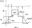
На фиг.2 показаны эпюры сигнала набега фазы Δφ(t), данных N(ti) управления частотой генератора, единичная импульсная последовательность L(ti) дискретных приращений фазы, а также частотные ошибки слежения Δω1, Δω2, Δω3 и весовой коэффициент S шага дискретности следящего фильтра.Figure 2 shows the plot of the phase incursion signal Δφ (t), data of the generator frequency control data N (t i ), a single pulse sequence L (t i ) of discrete phase increments, as well as the tracking frequency errors Δω1, Δω2, Δω3 and weight coefficient S pitch of discreteness of the tracking filter.
На фиг.3 представлены результаты измерений на тестовом объекте степени турбулентности Tu при изменении быстродействия следящего фильтра и изменении концентрации частиц.Figure 3 presents the results of measurements on the test object of the degree of turbulence Tu when changing the speed of the servo filter and changing the concentration of particles.
Заявленное устройство работает следующим образом. Комплексный доплеровский сигнал ![]()
![]()
![]()
![]()
![]()
![]()
Далее сигнал разностной частоты Δω=ωД-ωГ фильтруется в блоке 2. Сигнал на выходе этого фильтра является комплексной огибающей входного сигнала, когда разностная частота Δω стремится к нулю. С выхода фильтра 2 сигнал подается на вход блока СОФАЗ 3 и далее - на асинхронный дельта-модулятор 4, с помощью которого формируется единичная импульсная последовательность L(ti) приращений набега фазы Δφ(t)=Δω·t во время ΔTi существования доплеровского сигнала с учетом ее знака. Шаг дискретности фазы при этом равен Δφ, а время ΔTi определяется длительностью импульса при превышении А2(t) заданного порога. Далее импульсная последовательность L(ti) суммируется в схеме формирователя сигнала управления 5, где формируется код N(ti) управления частотой генератора 6. Таким образом, замыкается цепь обратной связи и осуществляется слежение за частотой входного сигнала. При этом, как отмечалось выше, точность слежения оказывается недостаточной. Для того чтобы повысить точность измерений, вводится цепь коррекции показаний следящего фильтра. Она содержит измеритель интервалов Δti+1 времени (блок 7) между импульсами единичной последовательности L(ti). Код N(ti) управления и код N(Δti+1) времени Δti+1 поступают на вычислительное устройство 8, где осуществляется коррекция показаний следящего фильтра в соответствии с выражением ![]()
![]()
![]()
![]()
Технический результат от использования предлагаемого способа и устройства заключается в повышении точности оценки частоты входного сигнала, повышении надежности и стабильности работы всей системы.The technical result from the use of the proposed method and device is to increase the accuracy of estimating the frequency of the input signal, increasing the reliability and stability of the entire system.
Реализация устройства не вызывает трудностей, т.к. все блоки выполняются на основе известных и широко распространенных радиотехнических элементов. Современный уровень технологий позволяет реализовать предлагаемое техническое решение на цифровых программируемых структурах, реализуемых на базовых платформах ALTERA и XILINX и др.The implementation of the device does not cause difficulties, because all blocks are based on well-known and widespread radio engineering elements. The current level of technology allows us to implement the proposed technical solution on digital programmable structures implemented on the base platforms ALTERA and XILINX, etc.
Claims (1)
Priority Applications (1)
| Application Number | Priority Date | Filing Date | Title |
|---|---|---|---|
| RU2006143928/09A RU2346292C2 (en) | 2006-12-11 | 2006-12-11 | Method for generating tracking error signal and correction signal for input signal complex envelope tracking filter readings |
Applications Claiming Priority (1)
| Application Number | Priority Date | Filing Date | Title |
|---|---|---|---|
| RU2006143928/09A RU2346292C2 (en) | 2006-12-11 | 2006-12-11 | Method for generating tracking error signal and correction signal for input signal complex envelope tracking filter readings |
Publications (2)
| Publication Number | Publication Date |
|---|---|
| RU2006143928A RU2006143928A (en) | 2008-06-27 |
| RU2346292C2 true RU2346292C2 (en) | 2009-02-10 |
Family
ID=39679462
Family Applications (1)
| Application Number | Title | Priority Date | Filing Date |
|---|---|---|---|
| RU2006143928/09A RU2346292C2 (en) | 2006-12-11 | 2006-12-11 | Method for generating tracking error signal and correction signal for input signal complex envelope tracking filter readings |
Country Status (1)
| Country | Link |
|---|---|
| RU (1) | RU2346292C2 (en) |
Citations (5)
| Publication number | Priority date | Publication date | Assignee | Title |
|---|---|---|---|---|
| US4496949A (en) * | 1980-07-16 | 1985-01-29 | Selenia, Industrie Elettroniche Associate, S.P.A. | MTI Radar adaptable to different environmental conditions |
| US5081459A (en) * | 1989-11-17 | 1992-01-14 | Thomson-Csf | Doppler radar for the detection and localizing of helicopters |
| WO2003079046A1 (en) * | 2002-03-13 | 2003-09-25 | Raytheon Canada Limited | An adaptive system and method for radar detection |
| RU2252433C1 (en) * | 2004-01-08 | 2005-05-20 | Открытое акционерное общество "Научно-производственное предприятие "Радар ммс" | Tracking signal of a moving target's signal |
| RU2252432C1 (en) * | 2004-01-08 | 2005-05-20 | Открытое акционерное общество "Научно-производственное предприятие "Радар ммс" | Tracking filter of a moving target's signal |
-
2006
- 2006-12-11 RU RU2006143928/09A patent/RU2346292C2/en not_active IP Right Cessation
Patent Citations (5)
| Publication number | Priority date | Publication date | Assignee | Title |
|---|---|---|---|---|
| US4496949A (en) * | 1980-07-16 | 1985-01-29 | Selenia, Industrie Elettroniche Associate, S.P.A. | MTI Radar adaptable to different environmental conditions |
| US5081459A (en) * | 1989-11-17 | 1992-01-14 | Thomson-Csf | Doppler radar for the detection and localizing of helicopters |
| WO2003079046A1 (en) * | 2002-03-13 | 2003-09-25 | Raytheon Canada Limited | An adaptive system and method for radar detection |
| RU2252433C1 (en) * | 2004-01-08 | 2005-05-20 | Открытое акционерное общество "Научно-производственное предприятие "Радар ммс" | Tracking signal of a moving target's signal |
| RU2252432C1 (en) * | 2004-01-08 | 2005-05-20 | Открытое акционерное общество "Научно-производственное предприятие "Радар ммс" | Tracking filter of a moving target's signal |
Also Published As
| Publication number | Publication date |
|---|---|
| RU2006143928A (en) | 2008-06-27 |
Similar Documents
| Publication | Publication Date | Title |
|---|---|---|
| US6435038B1 (en) | Ultrasonic flow velocity measuring apparatus | |
| JP4904289B2 (en) | Ultrasonic flow sensor using modulo 2pi residue tracking | |
| US8508213B2 (en) | Frequency measurement device | |
| JP4962804B2 (en) | Coriolis flow meter | |
| US20190323878A1 (en) | Device and method for measurement of ultrasonic transit times | |
| TWI519790B (en) | Flow meter | |
| JP5682812B2 (en) | Frequency difference output device, frequency measurement device, electronic device, and frequency measurement method | |
| Sandenbergh et al. | Synchronizing network radar using all-in-view GPS-disciplined oscillators | |
| EP0097041B1 (en) | Correlation of noise signals | |
| US4616510A (en) | Fluid velocity measuring method and apparatus | |
| RU2346292C2 (en) | Method for generating tracking error signal and correction signal for input signal complex envelope tracking filter readings | |
| CN105717526B (en) | A kind of carrier phase cycle slip suppressing method based on phase error amplitude limiting processing | |
| CN104614545B (en) | Flow rate meter | |
| US7046345B2 (en) | Apparatus for precise distance measurement | |
| CN112835056A (en) | Doppler frequency shift signal processing method and circuit system for laser vibrometer | |
| EP0162987B1 (en) | Method and apparatus for the ultrasonic measuring of a fluid | |
| EP0250660B1 (en) | Fluid velocity measuring method and apparatus | |
| RU2225012C2 (en) | Phase-meter | |
| RU2794168C1 (en) | Multi-signal phase auto-tuning system | |
| EP2639590B1 (en) | Wide range, high resolution frequency monitor | |
| US12123758B2 (en) | Flow sensor performing multi level down sampling and method thereof | |
| US4183245A (en) | Synchronous frequency-to-voltage converter for doppler apparatus | |
| JPH03103724A (en) | Integrating device with fine flow rate cutting function | |
| RU2022297C1 (en) | Distance measuring combined system | |
| GB2099146A (en) | A phase difference flowmeter |
Legal Events
| Date | Code | Title | Description |
|---|---|---|---|
| MM4A | The patent is invalid due to non-payment of fees |
Effective date: 20161212 |