RU2334891C1 - Combined engine power plant - Google Patents
Combined engine power plant Download PDFInfo
- Publication number
- RU2334891C1 RU2334891C1 RU2007109031/06A RU2007109031A RU2334891C1 RU 2334891 C1 RU2334891 C1 RU 2334891C1 RU 2007109031/06 A RU2007109031/06 A RU 2007109031/06A RU 2007109031 A RU2007109031 A RU 2007109031A RU 2334891 C1 RU2334891 C1 RU 2334891C1
- Authority
- RU
- Russia
- Prior art keywords
- engine
- internal combustion
- propulsion system
- electric
- generator
- Prior art date
Links
Images


Classifications
-
- Y—GENERAL TAGGING OF NEW TECHNOLOGICAL DEVELOPMENTS; GENERAL TAGGING OF CROSS-SECTIONAL TECHNOLOGIES SPANNING OVER SEVERAL SECTIONS OF THE IPC; TECHNICAL SUBJECTS COVERED BY FORMER USPC CROSS-REFERENCE ART COLLECTIONS [XRACs] AND DIGESTS
- Y02—TECHNOLOGIES OR APPLICATIONS FOR MITIGATION OR ADAPTATION AGAINST CLIMATE CHANGE
- Y02T—CLIMATE CHANGE MITIGATION TECHNOLOGIES RELATED TO TRANSPORTATION
- Y02T10/00—Road transport of goods or passengers
- Y02T10/10—Internal combustion engine [ICE] based vehicles
- Y02T10/12—Improving ICE efficiencies
Abstract
Description
Изобретение относится к двигателестроению.The invention relates to engine building.
Известен авиационный комбинированный двигатель по заявке РФ на изобретение №2002115896, содержащий ГТД и ракетный двигатель.Known aircraft combined engine according to the application of the Russian Federation for invention No. 2002115896, containing a gas turbine engine and a rocket engine.
Недостаток - очень большой расход топлива, потребляемый ракетным двигателем.The disadvantage is the very high fuel consumption consumed by the rocket engine.
Известна двигательная установка по патенту РФ №2211935, прототип, содержащая компрессор, камеру сгорания, турбину и реактивное сопло.Known propulsion system according to the patent of the Russian Federation No. 2211935, a prototype containing a compressor, a combustion chamber, a turbine and a jet nozzle.
Недостаток - низкий КПД, большой удельный расход топлива, наличие значительного количества вредных веществ в выхлопном газе.The disadvantage is low efficiency, high specific fuel consumption, the presence of a significant amount of harmful substances in the exhaust gas.
Задачи создания изобретения: улучшение экологических свойств, повышение КПД, снижение веса, стоимости и повышение надежности двигательной установки.Objectives of the invention: improving environmental properties, increasing efficiency, reducing weight, cost and improving the reliability of the propulsion system.
Решение указанных задач достигнуто в комбинированной двигательной установке, содержащей двигатель внутреннего сгорания, соединенный валом с ротором генератора, и двигатель Стирлинга, тем, что генератор выполнен биротативным с двумя роторами, причем ко второму ротору генератора присоединен вал двигателя Стирлинга. Оба ротора электрогенератора выполнены с возможностью вращения в разные стороны. Установка может быть оборудована или единой топливной системой для двигателя внутреннего сгорания и двигателя Стирлинга, или топливные системы для двигателя внутреннего сгорания и двигателя Стирлинга выполнены раздельными. Установка может содержать вентилятор, а двигатель Стирлинга содержит, по меньшей мере, один рабочий цилиндр и, по меньшей мере, один расширительный цилиндр, установленный за вентилятором по потоку воздуха. Каждый расширительный цилиндр имеет кожух, образующий с этим цилиндром охлаждающую полость, вход в охлаждающую полость соединен с воздухозаборным патрубком, а выход из охлаждающей полости соединен с выхлопным патрубком. К электрогенератору подключен, по меньшей мере, один электродвигатель. К электрогенератору через коммутатор подключен накопитель электроэнергии. Электродвигатель установлен на оси двигателя внутреннего сгорания.The solution of these problems was achieved in a combined propulsion system containing an internal combustion engine connected by a shaft to the generator rotor and a Stirling engine, in that the generator is made biotative with two rotors, and the Stirling engine shaft is connected to the second rotor of the generator. Both rotors of the generator are rotatable in different directions. The installation can be equipped with either a single fuel system for an internal combustion engine and a Stirling engine, or the fuel systems for an internal combustion engine and a Stirling engine are separate. The installation may include a fan, and the Stirling engine contains at least one working cylinder and at least one expansion cylinder mounted behind the fan in an air stream. Each expansion cylinder has a casing that forms a cooling cavity with this cylinder, the entrance to the cooling cavity is connected to the air intake pipe, and the outlet from the cooling cavity is connected to the exhaust pipe. At least one electric motor is connected to the electric generator. An electric energy storage device is connected to the electric generator through the switch. The electric motor is mounted on the axis of the internal combustion engine.
Предложенное техническое решение обладает новизной, изобретательским уровнем и промышленной применимостью, что подтверждается проведенными патентными исследованиями. Для реализации изобретения достаточно применения известных узлов и деталей, ранее разработанных и реализованных в конструкции газотурбинных двигателей и в машиностроении.The proposed technical solution has novelty, inventive step and industrial applicability, as evidenced by patent research. To implement the invention, it is sufficient to use the known components and parts previously developed and implemented in the design of gas turbine engines and in mechanical engineering.
Комбинированными (гибридными) называются агрегаты, способные работать на нескольких видах горючего топлива, и двигатели с так называемым послойным смесеобразованием. Многотопливные моторы обладают достаточно сложной конструкцией и работают на чрезвычайно высоких степенях сжатия. Так, например, в двигателе MTU (Mercedes-Benz) последняя составляет 25 единиц. В то время как у современных массовых агрегатов, потребляющих высокооктановый бензин, степень сжатия колеблется от 9 до 10 единиц, а у дизелей лежит в пределах 16-17. Одним из простейших примеров подобных силовых установок можно считать мотор, работающий на бензине и газе (природном или полученном из нефти). Такие двигатели пользуются популярностью в странах с высокими ценами на бензин (Италия, государства Южной Америки). Послойное смесеобразование применяется в бензиновых агрегатах для снижения расхода топлива и вредных выбросов на средних нагрузках. Кроме двух вышеназванных типов существовал и еще один - гибридный, представляющий собой работающие в паре ДВС и электродвигатель. Почему-то создается ощущение, что данная технология родилась совсем недавно. На самом деле такой двигатель появились на рубеже XIX-XX-го веков. Более того, некоторым разработчикам удалось перейти от проектов к мелкосерийному производству. Начиная с 1897 года и на протяжении 10 последующих лет французская Compagnie Parisienne des Voitures Electriques выпустила партию электромобилей и машин с гибридными двигателями. В 1900 году General Electric сконструировала гибридный автомобиль с 4-цилиндровым бензиновым мотором. А с конвейера Walker Vehicle Company of Chicago "гибридные" грузовики сходили до 1940 года.Combined (hybrid) are called units capable of operating on several types of combustible fuel, and engines with the so-called layer-by-layer mixing. Multi-fuel engines have a fairly complex design and operate at extremely high compression ratios. So, for example, in the MTU engine (Mercedes-Benz), the latter is 25 units. While modern mass units consuming high-octane gasoline, the compression ratio ranges from 9 to 10 units, and for diesel engines lies in the range 16-17. One of the simplest examples of such power plants can be considered a motor running on gasoline and gas (natural or derived from oil). Such engines are popular in countries with high gas prices (Italy, South America). Layered mixing is used in gasoline units to reduce fuel consumption and harmful emissions at medium loads. In addition to the two types mentioned above, there was one more - a hybrid one, which was a combination of internal combustion engines and an electric motor. For some reason, it seems that this technology was born recently. In fact, such an engine appeared at the turn of the XIX-XX centuries. Moreover, some developers managed to move from projects to small-scale production. Beginning in 1897 and over the next 10 years, the French Compagnie Parisienne des Voitures Electriques launched a batch of electric vehicles and cars with hybrid engines. In 1900, General Electric designed a hybrid car with a 4-cylinder gasoline engine. And from the conveyor of the Walker Vehicle Company of Chicago, “hybrid” trucks left until 1940.
Почему же тогда идея электродвигателей и гибридов не прижилась? Бензиновый двигатель занял первое место по скорости и намного превзошел электрический по запасу хода, зато по надежности и КПД бензиновый ДВС проиграл. Стоит заметить, что ресурсные и экологические проблемы в прежние времена еще не рассматривались. Продвижению же гибридного двигателя "в массы" тогда помешала высокая цена комплектующих электроустановок, а также малые мощности и непомерный вес элементов питания (аккумуляторных батарей).Why, then, did the idea of electric motors and hybrids not take root? The gas engine ranks first in speed and far surpasses the electric in terms of range, but in terms of reliability and efficiency, the gas engine has lost. It is worth noting that resource and environmental problems in former times have not yet been considered. The promotion of the hybrid engine "to the masses" was then prevented by the high price of components for electrical installations, as well as the low power and exorbitant weight of batteries (batteries).
Совершенствование двигателей внутреннего сгорания едва поспевает за предъявляемыми к ним требованиями. С одной стороны, потребителям нужен мощный и экономичный мотор, экологам ужесточающие нормы токсичности, геологи настойчиво напоминают об истощении запасов "черного золота". Эпоха ДВС как основного источника энергии на автомобиле подходит к логическому завершению. Подтверждение этому уже не опытные, а серийные модели с гибридными силовыми установками. Спустя ровно 110 лет (в 1997 году) после появления первого гибридного автомобиля компания Toyota представила массовую модель Prius. Изюминка Prius - электромотор, батарею которого не надо заряжать от внешней сети. Энергия для заряда аккумулятора вырабатывается прямо на борту автомобиля. Мощность 1,5-литрового бензинового двигателя этой модели - 53 кВт (57 кВт - Prius 2-го поколения), тягового электромотора - 33 кВт (50 кВт - Prius 2-го поколения). Максимальная скорость составляет 160 км/ч, а расход топлива 4,6 л (4 л - Prius 2-го поколения) на 100 км. В 2004 году на Международном конкурсе в Германии силовой агрегат Toyota Prius занял первые места сразу в четырех (!) номинациях, в том числе и в самой престижной - "Лучший двигатель 2004 года". Toyota Motor Corp приступила к продаже первого седана с гибридным электро-бензиновым двигателем марки Lexus в Японии. Второй по величине в мире автопроизводитель заявил, что стремится вдвое сократить расходы на производство гибридных двигателей и цену на них. В 2005 корпорация Toyota Motor разработала гибридный двигатель третьего поколения, совмещающий в себе бензин и электроэнергию. Этот двигатель меньшего размера, который позволит сократить затраты как на топливо, так и на производство, будет применяться на практике в 2008 году. Французский концерн PSA Peugeot/Citroen представил первый дизельный гибридный двигатель, состоящий из гибридного приводного узла и двигателя HDL, то есть объединяет в себе традиционный дизель и электромотор. По словам французов, новый силовой агрегат будет отличаться очень низким расходом топлива (ниже на 20% по сравнению с бензиновым двигателем =3,4 л на 100 км и выбросу CO2 (90 г/км)), ведь дизельный мотор потребляет меньше горючего, чем его бензиновый аналог. При этом полностью сохраняя высокие динамические характеристики, присущие семейству дизельных двигателей типа Hdi плюс преимущества, свойственные гибридному приводному узлу (например, движение в режиме электромобиля на невысокой скорости). Однако появления гибридного дизеля на серийных машинах придется подождать - представители PSA заявили, что он пойдет в производство примерно в 2010 году. Компания Ford выпустила второй в 2005 году автомобиль, работающий на гибридном двигателе. Модель Mercury Mariner Hybrid поступила в продажу 11 июля. Этот автомобиль стоит $29840, что на $4190 дороже варианта с обычным двигателем. Вместе с тем. Mercury Mariner Hybrid позволяет сэкономить до 50% топлива по сравнению с традиционной машиной. В 2006 году планируется выпустить 2 тыс. экземпляров Mercury Mariner Hybrid. Volvo Group в марте 2006 года объявила о создание гибридного двигателя для тяжелых машин, таких как тягачи полуприцепов и автобусы. Компания заявляет, что их разработка позволяет получить 35% экономию топлива в условиях города с интенсивным движением. Важная часть новой гибридной технологии, получившая название I-SAM. Любое транспортное средство, которое имеет два или более источников энергии, остаточной для движения, можно назвать гибридным. Бензиновый двигатель внутреннего сгорания (ДВС) - гибридная машина имеет привычный бензиновый двигатель. Хотя современные высокие технологии позволяют делать его меньшим по габаритам, более экологичным и экономичным. Топливный бак - здесь хранится топливо для двигателя. Бензин обладает большим энергетическим запасом, нежели электрические батареи. Для примера, батареи весом 450 кг отдадут столько же энергии, сколько и 3,5 кг бензина. Электромотор - очень "продвинутый" элемент. Современная электроника делает его и мотором и генератором одновременно. Например, когда это необходимо, энергия берется из электрических батарей и ускоряет автомобиль. Но тормозя машину, двигатель переходит в режим генератора и восстанавливает энергию. Генератор - схож с электромотором, но работает только в режиме запасания энергии (используется, главным образом, в серийных гибридных автомобилях). Батареи - источник энергии для электромотора в отличие бензинового ДВС электромотор может не только "брать" энергию, но и запасать ее в батареях. Трансмиссия - функции те же, что и у трансмиссии на традиционных автомобилях с ДВС. Некоторые гибридные машины (Honda, например) имеют стандартную трансмиссию, другие же (Toyota Prius) оснащаются радикально новой.Improvement of internal combustion engines is barely keeping up with the requirements for them. On the one hand, consumers need a powerful and economical engine, environmentalists are tightening toxic standards, geologists are persistently reminded of the depletion of "black gold". The era of internal combustion engines as the main source of energy in a car is approaching its logical conclusion. Confirmation of this is not experienced, but serial models with hybrid power plants. Exactly 110 years (in 1997) after the appearance of the first hybrid car, Toyota introduced the mass model Prius. The highlight of the Prius is an electric motor whose battery does not need to be charged from an external network. Energy to charge the battery is generated directly on board the car. The power of the 1.5-liter gasoline engine of this model is 53 kW (57 kW - Prius of the 2nd generation), traction electric motor - 33 kW (50 kW - Prius of the 2nd generation). The maximum speed is 160 km / h, and fuel consumption is 4.6 liters (4 liters - 2nd generation Prius) per 100 km. In 2004, at the International Competition in Germany, the Toyota Prius power unit won first places in four (!) Categories at once, including in the most prestigious - "Best Engine of 2004". Toyota Motor Corp launched the first Lexus hybrid electric gasoline sedan in Japan. The world's second largest carmaker said it seeks to halve the costs of producing hybrid engines and their price. In 2005, Toyota Motor Corporation developed a third-generation hybrid engine that combines gasoline and electricity. This smaller engine, which will reduce both fuel and production costs, will be put into practice in 2008. The French concern PSA Peugeot / Citroen introduced the first diesel hybrid engine consisting of a hybrid drive unit and an HDL engine, that is, it combines a traditional diesel engine and an electric motor. According to French, the new powertrain will differ very low fuel consumption (lower by 20% compared with a gasoline engine of 3.4 L = 100 km and release of CO 2 (90 g / km)), because the diesel engine consumes less fuel, than its gasoline counterpart. At the same time, it fully preserves the high dynamic characteristics inherent in the Hdi family of diesel engines, plus the advantages inherent in a hybrid drive unit (for example, driving in an electric car at low speed). However, the appearance of a hybrid diesel engine on production cars will have to wait - PSA representatives said that it will go into production around 2010. Ford released its second hybrid car in 2005. The Mercury Mariner Hybrid went on sale July 11th. This car costs $ 29,840, which is $ 4,190 more expensive than the option with a conventional engine. At the same time. Mercury Mariner Hybrid saves up to 50% on fuel compared to a traditional machine. In 2006, it is planned to release 2 thousand copies of the Mercury Mariner Hybrid. The Volvo Group in March 2006 announced the creation of a hybrid engine for heavy vehicles such as semi-trailers and buses. The company claims that their development provides 35% fuel savings in a city with heavy traffic. An important part of the new hybrid technology, called I-SAM. Any vehicle that has two or more sources of energy, residual for movement, can be called hybrid. Gasoline internal combustion engine (ICE) - The hybrid car has a familiar gasoline engine. Although modern high technology allows you to make it smaller in size, more environmentally friendly and economical. Fuel tank - fuel for the engine is stored here. Gasoline has a greater energy reserve than electric batteries. For example, batteries weighing 450 kg will give as much energy as 3.5 kg of gasoline. The electric motor is a very "advanced" element. Modern electronics makes it both a motor and a generator at the same time. For example, when necessary, energy is taken from electric batteries and accelerates the car. But braking the car, the engine goes into generator mode and restores energy. The generator is similar to an electric motor, but it works only in the energy storage mode (it is used mainly in serial hybrid cars). Batteries - an energy source for an electric motor, unlike a gasoline ICE, an electric motor can not only “take” energy, but also store it in batteries. Transmission - the functions are the same as the transmission on traditional cars with ICE. Some hybrid cars (Honda, for example) have a standard transmission, while others (Toyota Prius) are equipped with a radically new one.
В многих разработках применена последовательная схема работы. В данном случае ДВС приводит в движение генератор, а вырабатываемая последним электроэнергия питает электродвигатель, вращающий ведущие колеса. Последовательной установку называют потому, что поток мощности поступает на ведущие колеса, проходя ряд преобразований. От механической энергии, вырабатываемой ДВС в электрическую, вырабатываемую генератором, и опять в механическую. Данная схема позволяет использовать ДВС малой мощности с условием его постоянной работы в диапазоне максимального КПД. Это позволит стабильно генерировать достаточное количество энергии для питания электродвигателя и заряда аккумуляторной батареи.Many developments use a consistent workflow. In this case, the internal combustion engine drives the generator, and the electricity generated by the latter feeds the electric motor that rotates the drive wheels. A sequential installation is called because the flow of power enters the drive wheels through a series of conversions. From the mechanical energy generated by the internal combustion engine to the electrical energy generated by the generator, and again into the mechanical. This scheme allows the use of low-power ICE with the condition of its constant operation in the range of maximum efficiency. This will allow stably generating enough energy to power the electric motor and charge the battery.
Иногда применяют параллельную схему. Здесь ведущие колеса приводятся в движение и ДВС, и электродвигателем (обратимой машиной). Момент, поступающий от двух источников, распределяется в соответствии с условиями движения. Аккумулятор заряжается при переключении электродвигателя в режим генератора (например, при торможении), а запасенная батареей энергия питает обратимую машину, переключившуюся в режим электродвигателя, которая, в свою очередь, вращает ведущие колеса. Подобная конструкция достаточно проста, но имеет ряд недостатков, так как обратимая машина гибридной силовой установки не может одновременно приводить в движение колеса и заряжать батарею. Последовательно - параллельная схема. Эта схема объединяет в себе две предыдущие. Здесь в зависимости от условий движения используется тяга электродвигателя или одновременно ДВС и электродвигателя. Помимо этого в случае необходимости система способна приводить колеса в движение и одновременно вырабатывать электроэнергию, используя генератор. Таким образом, достигается максимальная эффективность силовой установки.Sometimes a parallel circuit is used. Here, the drive wheels are driven by both the internal combustion engine and the electric motor (reversible machine). The moment coming from two sources is distributed in accordance with the traffic conditions. The battery is charged when the electric motor is switched to generator mode (for example, when braking), and the energy stored by the battery feeds the reversible machine, which switches to electric motor mode, which, in turn, rotates the drive wheels. This design is quite simple, but has several disadvantages, since a reversible hybrid power plant cannot simultaneously set the wheels in motion and charge the battery. In series - parallel circuit. This scheme combines the two previous ones. Here, depending on the driving conditions, the thrust of the electric motor is used, or at the same time the internal combustion engine and electric motor. In addition, if necessary, the system is able to set the wheels in motion and simultaneously generate electricity using a generator. Thus, the maximum efficiency of the power plant is achieved.
Практический примерPractical example
Новинка компании Toyota - Lexus RX400h, оснащенная последовательно-параллельной гибридной силовой установкой Hybrid Synergy Drive. Гибридная установка Lexus RX400h сочетает в себе бензиновый V-образный шестицилиндровый двигатель объемом 3,3 л, мощностью 150 кВт, 2 электромотора мощностью 200 кВт, с рабочим напряжением 650 В и высоковольтную аккумуляторную батарею напряжением 288 В. Соединить напрямую ДВС, электромоторы и аккумулятор и добиться при этом согласованной работы невозможно. Бензиновый двигатель V-образная "шестерка" оснащена сложной компьютерной системой, осуществляющей непрерывную корректировку количества воздуха, поступающего в цилиндры. Благодаря этому удалось добиться соблюдения норм Евро-4. Высоковольтные моторы, по сути, являются обратимыми машинами, т.е. могут работать как в двигательном, так и в генераторном режиме. Располагаются в передней и задней частях автомобиля и приводят в движение соответственно колеса переднего и заднего мостов. Устройство распределения энергии - это связующее звено между ДВС, электромоторами и генератором. "Сердце" устройства распределения энергии - компактная планетарная передача. Она обладает малой массой и меньшим количеством движущихся частей в сравнении с 5- или 6-ступенчатыми АКПП автомобилей класса "люкс". Применение планетарной передачи позволило снизить потери на трение и шум при работе и в то же время повысить надежность и срок службы узла. Энергетический центр - уникальная система, управляющая созданием и распределением запасов электрической энергии, хранящейся в батарее. Основные компоненты энергетического центра: мощная высоковольтная батарея (NiMH), блок управления энергией, полупроводниковое коммутационное устройство, рекуперативная (регенеративная) тормозная система. Блок управления энергией и полупроводниковое устройство переключения управляют потоком энергии между генератором, батареей и электромоторами. Данные устройства осуществляют преобразование электроэнергии в соответствии с потребностями системы. Потребность в преобразовании продиктована следующими причинами: генератор и электромоторы - машины переменного тока, в то время как аккумуляторная батарея оперирует постоянным, кроме того, выходное напряжение батареи не соответствует выходному напряжению генератора, а также входному напряжению электромоторов. Инвертор - блок, преобразующий постоянный ток, поступающий от аккумуляторной батареи, в переменный, используемый для питания электромоторов. В гибридной силовой установке Lexus RX400h предусмотрена высоковольтная схема преобразования одного постоянного тока в другой, тоже постоянный. Но поскольку она повышает напряжение, то происходит равномерный рост электрической мощности при той же величине значения тока. В результате получают более высокую производительность и повышенный крутящий момент привода электромоторов. Рекуперативная (регенеративная) тормозная система - при торможении система переводит моторы в генераторный режим. Вырабатываемая при этом электроэнергия поступает на вход аккумуляторной батареи. Особо эффективную работу система показала в городских условиях, при чередовании режимов стоп - старт. Заметим, что в традиционных тормозных системах энергия, полученная при замедлении, теряется полностью. Система интегрированного управления динамикой автомобиля (VDIM) объединяет воедино системы активной безопасности, такие как антиблокировочная система тормозов (ABS), антипробуксовочная система (TRC), система курсовой устойчивости (VCS) и электроусилитель руля (EPS). VDIM не столь "навязчива", как обычные системы управления, но намного более эффективна. При помощи высокоскоростной технологии управления двигателем, тормозами и трансмиссией VDIM контролирует и сопоставляет все параметры, одновременно управляя крутящим моментом переднего и заднего электромоторов в соответствии с условиями движения.Toyota's new product is the Lexus RX400h, equipped with a Hybrid Synergy Drive series-parallel hybrid propulsion system. The Lexus RX400h hybrid installation combines a 3.3 L, 150 kW gasoline V-shaped six-cylinder engine, 2 200 kW electric motors, 650 V operating voltage and a 288 V high-voltage battery. Directly connect the internal combustion engines, electric motors and battery and while achieving coordinated work is impossible. The V-shaped gasoline engine is equipped with a sophisticated computer system that continuously adjusts the amount of air entering the cylinders. Thanks to this, it was possible to achieve compliance with Euro-4 standards. High-voltage motors, in fact, are reversible machines, i.e. can work both in motor and in generator mode. They are located in the front and rear parts of the car and drive the wheels of the front and rear axles, respectively. An energy distribution device is a connecting link between an internal combustion engine, electric motors and a generator. The "heart" of the energy distribution device is a compact planetary gear. It has a low weight and fewer moving parts in comparison with 5- or 6-speed automatic transmissions of luxury cars. The use of planetary gear allowed to reduce friction and noise losses during operation and at the same time increase the reliability and service life of the assembly. The Energy Center is a unique system that governs the creation and distribution of electrical energy stored in a battery. The main components of the energy center: a powerful high-voltage battery (NiMH), an energy control unit, a semiconductor switching device, a regenerative (regenerative) braking system. An energy control unit and a semiconductor switching device control the flow of energy between the generator, battery and electric motors. These devices convert electricity according to the needs of the system. The need for conversion is dictated by the following reasons: the generator and electric motors are AC machines, while the battery operates constant, in addition, the output voltage of the battery does not correspond to the output voltage of the generator, as well as the input voltage of the electric motors. An inverter is a unit that converts direct current from a battery into alternating current used to power electric motors. The Lexus RX400h hybrid powerplant provides a high-voltage circuit for converting one direct current to another, also constant. But since it increases the voltage, a uniform increase in electric power occurs at the same current value. The result is a higher performance and increased torque drive electric motors. Regenerative (regenerative) braking system - when braking, the system puts the motors in generator mode. The electricity generated in this case is fed to the input of the battery. The system showed particularly effective operation in urban conditions, with the alternation of stop - start modes. Note that in traditional brake systems, the energy obtained during deceleration is completely lost. The Integrated Vehicle Dynamics Control (VDIM) system combines active safety systems such as anti-lock brakes (ABS), traction control (TRC), directional stability control (VCS) and electric power steering (EPS). VDIM is not as "intrusive" as conventional control systems, but much more efficient. Using high-speed technology for controlling the engine, brakes and transmission, VDIM monitors and compares all parameters, while simultaneously controlling the torque of the front and rear electric motors in accordance with driving conditions.
Режимы движенияDriving modes
В этом разделе мы рассмотрим особенности работы системы при выполнении различных маневров.In this section, we will consider the features of the system when performing various maneuvers.
Начало движенияStart of movement
Для начала движения и на малых скоростях используется только электромотор. При плавном наборе скорости энергия, запасенная в батарее, поступает на блок управления электропитанием. Последний, в свою очередь, направляет энергию на электромоторы, что позволяет автомобилю плавно трогаться с места. Движение в нормальном режиме: в этом случае момент на ведущие колеса поступает с ДВС и электромоторов; энергия бензинового двигателя распределяется между колесами и электрическим генератором, приводящим в движение электромоторы. При необходимости генератор осуществляет заряд батареи, отдавая ей излишки энергии. В целях обеспечения максимальной эффективности распределение энергии контролируется электронным блоком управления.To start the movement and at low speeds, only an electric motor is used. With a smooth set of speeds, the energy stored in the battery is supplied to the power control unit. The latter, in turn, directs energy to electric motors, which allows the car to move smoothly. Movement in normal mode: in this case, the moment to the drive wheels comes from the internal combustion engine and electric motors; the energy of a gasoline engine is distributed between the wheels and an electric generator that drives electric motors. If necessary, the generator charges the battery, giving it excess energy. In order to ensure maximum efficiency, energy distribution is controlled by an electronic control unit.
При движении в нормальном режиме система автоматически переходит на передний привод, в то время как на всех остальных сохраняется полный. Разгон: бензиновый двигатель разгоняет машину, работая в нормальном режиме, при необходимости и для улучшения динамики дополнительная энергия поступает от электромоторов. Это создает ощущение, что ДВС гораздо мощнее, чем есть на самом деле. Интересно сравнить эту систему с турбированным двигателем. В то время как работа последнего может сопровождаться "турбозадержками", гибридный вариант обеспечивает практически мгновенную подачу дополнительной энергии, что позволяет получить плоскую характеристику крутящего момента. Для оптимизации количества сохраняемой энергии управляемая электроникой тормозная система принимает решение о том, когда следует использовать гидравлическую систему, а когда - рекуперативное (регенеративное) торможение (оно и является приоритетным). При рекуперативном торможении передний и задний электродвигатели работают в генераторном режиме, создавая тормозной момент на передней и задней осях. Вырабатываемая энергия поступает на блок управления электропитанием, а оттуда на высоковольтную аккумуляторную батарею.When driving in normal mode, the system automatically switches to front-wheel drive, while on all others the full drive is maintained. Acceleration: the gasoline engine accelerates the car, working in normal mode, if necessary and to improve dynamics, additional energy comes from electric motors. This creates the feeling that the internal combustion engine is much more powerful than it really is. It is interesting to compare this system with a turbocharged engine. While the operation of the latter may be accompanied by "turbo-delays", the hybrid version provides almost instantaneous supply of additional energy, which allows to obtain a flat torque characteristic. To optimize the amount of energy stored, the electronically controlled brake system decides when to use the hydraulic system and when to use regenerative (regenerative) braking (which is the priority). During regenerative braking, the front and rear electric motors operate in generator mode, creating braking torque on the front and rear axles. The generated energy is supplied to the power control unit, and from there to the high-voltage battery.
К достоинствам гибридного автомобиля можно отнести то, что он гораздо меньше по сравнению с обычным автомобилем и при этом более эффективен. Но как же такой маленький автомобиль может уживаться на дороге со своими более мощными собратьями? Если сравним Chevrolet Camaro с его огромной V-образной "восьмеркой" с нашей гибридной машиной, с ее маленьким ДВС и электромотором. Мощности двигателя Camaro вполне достаточно для того, чтобы справиться с любой дорожной ситуацией. Мотора же гибрида достаточно для движения по ровной дороге, но как только нужно въехать на склон, он получает дополнительную мощность от электромотора с его батареями. Эта система и предоставляет необходимую добавку энергии.The advantages of a hybrid car include the fact that it is much smaller compared to a conventional car and is more efficient. But how can such a small car get along on the road with its more powerful brothers? If we compare the Chevrolet Camaro with its huge V-shaped “eight” with our hybrid car, with its small ICE and electric motor. Camaro engine power is enough to cope with any traffic situation. The hybrid motor is enough to drive on a flat road, but as soon as you need to drive onto the slope, it receives additional power from the electric motor with its batteries. This system provides the necessary energy supplement.
Большинству автомобилей достаточно 20 л.с. для движения со скоростью около 100 км/час. Так зачем же тогда вам нужен двигатель мощностью до 300 л.с? Полная мощность может быть никогда не использована. Расход же топлива у ДВС всегда в десятки раз больше и пропорционально больше выделение вредных веществ в атмосферу.Most cars only need 20 hp. for movement at a speed of about 100 km / h. So why then do you need an engine with power up to 300 hp? Full power can never be used. The fuel consumption of the internal combustion engine is always ten times more and proportionally more harmful emissions into the atmosphere.
Сущность изобретения поясняется на фиг.1...8, где:The invention is illustrated in figure 1 ... 8, where:
на фиг.1 приведена схема двигательной установки с единой топливной системой для ДВС и двигателя Стерлинга,figure 1 shows a diagram of a propulsion system with a single fuel system for internal combustion engines and a Sterling engine,
на фиг.2 и 3 приведена схема двигателя Стерлинга,figure 2 and 3 shows a diagram of a sterling engine,
на фиг.4 приведена электрическая схема установки с одним электродвигателем,figure 4 shows the electrical circuit of the installation with one electric motor,
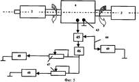
на фиг.5 приведена схема установки с двумя электродвигателями,figure 5 shows the installation diagram with two electric motors,
на фиг.6 приведена схема установки с электродвигателем, установленным на одном валу с ДВС,figure 6 shows the installation diagram with an electric motor mounted on the same shaft with the internal combustion engine,
на фиг.7 приведена схема установки с двумя электродвигателем, причем один из них установлен на валу ДВС,Fig.7 shows a diagram of an installation with two electric motors, and one of them is installed on the ICE shaft,
на фиг.8 приведена схема двигательной установки с раздельными топливными системами для ДВС и для двигателя Стерлингаon Fig shows a diagram of a propulsion system with separate fuel systems for internal combustion engines and for the Stirling engine
Предложенное техническое решение (фиг.1) содержит установленные на раме 1 двигатель внутреннего сгорания 2, двигатель Стерлинга 3 и электрогенератор 4. Двигатель Стерлинга 3 закреплен на раме 1 при помощи кронштейна 5, а электрогенератор 4 установлен на опоре 6, которая также закреплена на раме 1.The proposed solution (Fig. 1) contains an
Двигатель внутреннего сгорания 2 содержит кожух радиатора 7, радиатор 8, вентилятор 9, цилиндры 10 с поршнями 11, вал двигателя внутреннего сгорания 12, систему жидкостного охлаждения 13 с насосом 14 и полостью охлаждения «А» между цилиндрами 10, воздухозаборные патрубки 15 в выхлопные трубы 16. Кроме того, двигатель внутреннего сгорания 2 и двигатель Стерлинга 3 оборудованы или единой топливной системой 17 (фиг.1), или раздельными топливными системами (фиг.7). Единая топливная система 17 (фиг.1) содержит топливный насос 18 с топливопроводами 19, регуляторами расхода топлива 20 и топливными форсунками 21. Двигатель Стирлинга 3 состоит, по меньшей мере, из одного рабочего цилиндра и, по меньшей мере, одного расширительного цилиндра 23, соединенных трубопроводами 24, вала двигателя Стирлинга 25 и выхлопных патрубков 26, концы которых выходят в полость «Б», внутри выхлопного устройства установки 27. Кроме того, к расширительным цилиндрам 23 подведены от кожуха радиатора 7 воздуховоды 28, а к выхлопным патрубкам 16 подсоединены воздушные патрубки 29 с регуляторами расхода 30 для подвода дополнительного воздуха к двигателю Стирлинга 3, конкретно к его рабочим цилиндрам 22.The
Электрогенератор 4 выполнен биротативным и содержит статор 31 с обмоткой возбуждения 32, внешний ротор 33 с группой внешних постоянных магнитов 34, внутренний ротор 35 с группой внутренних постоянных магнитов 36, установленной на нем. Внутренний ротор 35 соединен с валом двигателя внутреннего сгорания 12, а внешний ротор 33 соединен с валом двигателя Стирлинга 25. Статор 31 находится между роторами 33 и 35.The
На фиг.2 и 3 приведена схема одного из вариантов исполнения двигателя Стирлинга 3, который содержит группу рабочих цилиндров 22, имеющих оребрение 36 с установленным внутри каждого из них в полости «Г» рабочим поршнем 37, который шатуном 38 соединен с валом двигателя внутреннего сгорания 12, и группу расширительных цилиндров 23 с установленным внутри каждого из них в полости «В» вытеснительным поршнем 41. Каждый расширительный цилиндр 23 оборудован снаружи кожухом 39, образующим полость «Д» для охлаждения расширительного цилиндра 23, на котором выполнены ребра 40. Вытеснительный поршень 41 соединен шатуном 42 с валом двигателя Стирлинга 25. Трубопровод 24 соединяет полости «Г» и «Д» для перетекания рабочего тела из рабочего цилиндра 22 в расширительный цилиндр 23. К полости «В» подсоединены воздуховоды 28 для подвода охлаждающего воздуха. Выхлопные патрубки 26 соединяют полость «Д» с внутренней полостью «Б» выхлопного устройства установки 27 (фиг.1).Figure 2 and 3 shows a diagram of one embodiment of a
К выходным клеммам 43 электрогенератора 4 подключены электрическими связями 44 коммутатор 45, инвертор 46 для преобразования постоянного тока в переменный, электродвигатель (или электродвигатели) 48. К коммутатору 45 подсоединен накопитель электроэнергии 49, например аккумулятор (фиг.4).The
При работе топливо подается по топливной системе 17 топливным насосом 18 или в двигатель внутреннего сгорания 2 или в двигатель Стерлинга 3 или одновременно в оба двигателя. Топливо воспламеняется при помощи электрозапальников (на фиг.1...3 не показано). Выхлопные газы проходят по выхлопным трубам 16 к рабочим цилиндрам 22 двигателя Стерлинга 3 и нагревают рабочее тело внутри полости «Г». Далее рабочее тело расширяется в полости в полости «Г».During operation, fuel is supplied through the
Шатуны 24 и 27 и поршни 37 и 39 двигателя Стерлинга 3 приводятся в действие при помощи вала двигателя Стерлинга 25, имеющего механизм преобразования вращательного движения в возвратно-поступательное (этот механизм на фиг.1...8 детально не показан, но он может быть выполнен в виде коленчатого вала). Выхлопные газы нагревают через оребрение 22 рабочее тело внутри рабочих цилиндров 19. Для работы двигателя Стерлинга 3 достаточно иметь разницу температур на двух группах цилиндров 22 и 23. Примерно через 5...10 мин по мере прогрева рабочего тела внутри рабочих цилиндров 22 двигателя Стерлинга 3 он выходит на расчетный режим работы. Медленный выход двигателя Стерлинга на расчетный режим работы является одним из его недостатков, но высокий КПД, надежность и хорошие экологические свойства в сочетании с ГТД, имеющим хорошие характеристики запуска, делает предложенный двигатель чрезвычайно интересным по всем показателям одновременно, и кроме того, позволит частично утилизировать тепло выхлопных газов.The connecting
В результате использования утилизации тепла выхлопных газов в двигателе Стерлинга КПД двигательной установки возрастает дополнительно на 10...15%.As a result of the use of heat recovery of exhaust gases in the Stirling engine, the efficiency of the propulsion system increases by an additional 10 ... 15%.
Применение изобретения позволило:The application of the invention allowed:
1. Значительно повысить КПД двигателя за счет использования для получения энергии на валу нагрузки кроме ГТД двигателя Стерлинга, который утилизирует тепло, раньше сбрасываемое в выхлопное устройство и в атмосферу.1. Significantly increase the efficiency of the engine due to the use for energy on the shaft of the load in addition to the gas turbine engine of the Stirling engine, which utilizes the heat previously discharged into the exhaust device and into the atmosphere.
3. Снизить эмиссию токсичных веществ в атмосферу за счет того, что двигатель Стерлинга имеет значительно лучшие экологические показатели по сравнению с другими типами двигателей.3. To reduce the emission of toxic substances into the atmosphere due to the fact that the Stirling engine has significantly better environmental performance compared to other types of engines.
4. Повысить надежность двигателя за счет возможности его эксплуатации при отказе одного из них.4. To increase the reliability of the engine due to the possibility of its operation in case of failure of one of them.
5. Использовать низкосортное топливо для двигателя Стерлинга.5. Use low-grade fuel for the Stirling engine.
Claims (9)
Priority Applications (1)
| Application Number | Priority Date | Filing Date | Title |
|---|---|---|---|
| RU2007109031/06A RU2334891C1 (en) | 2007-03-12 | 2007-03-12 | Combined engine power plant |
Applications Claiming Priority (1)
| Application Number | Priority Date | Filing Date | Title |
|---|---|---|---|
| RU2007109031/06A RU2334891C1 (en) | 2007-03-12 | 2007-03-12 | Combined engine power plant |
Publications (1)
| Publication Number | Publication Date |
|---|---|
| RU2334891C1 true RU2334891C1 (en) | 2008-09-27 |
Family
ID=39929021
Family Applications (1)
| Application Number | Title | Priority Date | Filing Date |
|---|---|---|---|
| RU2007109031/06A RU2334891C1 (en) | 2007-03-12 | 2007-03-12 | Combined engine power plant |
Country Status (1)
| Country | Link |
|---|---|
| RU (1) | RU2334891C1 (en) |
Cited By (2)
| Publication number | Priority date | Publication date | Assignee | Title |
|---|---|---|---|---|
| RU168553U1 (en) * | 2015-02-25 | 2017-02-08 | Владимир Сергеевич Иванов | Hybrid hydropower engine |
| RU174346U1 (en) * | 2016-09-21 | 2017-10-11 | Владимир Сергеевич Иванов | Power plant for a vehicle |
-
2007
- 2007-03-12 RU RU2007109031/06A patent/RU2334891C1/en active
Cited By (2)
| Publication number | Priority date | Publication date | Assignee | Title |
|---|---|---|---|---|
| RU168553U1 (en) * | 2015-02-25 | 2017-02-08 | Владимир Сергеевич Иванов | Hybrid hydropower engine |
| RU174346U1 (en) * | 2016-09-21 | 2017-10-11 | Владимир Сергеевич Иванов | Power plant for a vehicle |
Similar Documents
| Publication | Publication Date | Title |
|---|---|---|
| CN100421979C (en) | Power coupler for mixed power automobile | |
| CN100406289C (en) | Series-parallel mixed power system | |
| US6651760B2 (en) | Thermionic automobile | |
| US20130160722A1 (en) | Hybrid vehicle with exhaust powered turbo generator | |
| US5400596A (en) | Automotive system | |
| CN101209666A (en) | Mixed power outputting device | |
| US8004219B2 (en) | Operating method and system for hybrid vehicle | |
| CN102245931A (en) | Drive train having a first electric motor and a planetary gear mechanism, and wind energy plants, gas turbines and water turbines, and vehicles which have said drive train | |
| CN102815198A (en) | HEV (Hybrid Electric Vehicle) driving system based on CVT (Continuously Variable Transmission) | |
| CN102848913A (en) | Extended-range electric automobile power system adopting planetary transmission | |
| CN101152837B (en) | Driving device of hybrid vehicle | |
| CN101544181A (en) | Power assembly system | |
| CN102874092A (en) | Extended range electromobile power system using dual-clutch two-speed transmission | |
| CN102874094A (en) | Range extended electric vehicle power system adopting planetary gear two speed transmission | |
| US7419022B2 (en) | Thermionic power unit | |
| CN101734139A (en) | Power coupling transmission device of hybrid vehicle | |
| CN101701547A (en) | Vehicle-mounted generator of range-extended electric car | |
| WO2008122783A2 (en) | Hybrid vehicle | |
| CN102874107A (en) | Extended range electromobile power system using dual-clutch transmission gear | |
| RU2334891C1 (en) | Combined engine power plant | |
| CN102555764A (en) | Hybrid engine accessory driving system | |
| CN201002506Y (en) | Power coupling device for hybrid power automobile | |
| CN100430581C (en) | Method and equipment for reducing vehicle energy consumption | |
| Čeřovský et al. | Power electronics in automotive hybrid drives | |
| CN101934722A (en) | Hybrid power driving system in automobile |