RU2319023C2 - Method of operation of aircraft engine and anti-icing system (versions) - Google Patents
Method of operation of aircraft engine and anti-icing system (versions) Download PDFInfo
- Publication number
- RU2319023C2 RU2319023C2 RU2003120056/06A RU2003120056A RU2319023C2 RU 2319023 C2 RU2319023 C2 RU 2319023C2 RU 2003120056/06 A RU2003120056/06 A RU 2003120056/06A RU 2003120056 A RU2003120056 A RU 2003120056A RU 2319023 C2 RU2319023 C2 RU 2319023C2
- Authority
- RU
- Russia
- Prior art keywords
- engine
- membrane
- liquid
- reservoir
- aircraft
- Prior art date
Links
Images
Classifications
-
- F—MECHANICAL ENGINEERING; LIGHTING; HEATING; WEAPONS; BLASTING
- F02—COMBUSTION ENGINES; HOT-GAS OR COMBUSTION-PRODUCT ENGINE PLANTS
- F02C—GAS-TURBINE PLANTS; AIR INTAKES FOR JET-PROPULSION PLANTS; CONTROLLING FUEL SUPPLY IN AIR-BREATHING JET-PROPULSION PLANTS
- F02C7/00—Features, components parts, details or accessories, not provided for in, or of interest apart form groups F02C1/00 - F02C6/00; Air intakes for jet-propulsion plants
- F02C7/04—Air intakes for gas-turbine plants or jet-propulsion plants
- F02C7/047—Heating to prevent icing
-
- F—MECHANICAL ENGINEERING; LIGHTING; HEATING; WEAPONS; BLASTING
- F01—MACHINES OR ENGINES IN GENERAL; ENGINE PLANTS IN GENERAL; STEAM ENGINES
- F01D—NON-POSITIVE DISPLACEMENT MACHINES OR ENGINES, e.g. STEAM TURBINES
- F01D25/00—Component parts, details, or accessories, not provided for in, or of interest apart from, other groups
- F01D25/02—De-icing means for engines having icing phenomena
Abstract
Description
ОБЛАСТЬ ТЕХНИКИFIELD OF TECHNOLOGY
Настоящее изобретение относится к газотурбинным двигателям и более конкретно к способам и устройству работы газотурбинных двигателей.The present invention relates to gas turbine engines, and more particularly, to methods and apparatus for operating gas turbine engines.
ПРЕДШЕСТВУЮЩИЙ УРОВЕНЬ ТЕХНИКИBACKGROUND OF THE INVENTION
Газотурбинные двигатели обычно включают компрессоры высокого и низкого давления, камеру сгорания и по меньшей мере одну турбину. Компрессоры сжимают воздух, который смешивается с топливом и пропускается по каналу в камеру сгорания. Смесь затем воспламеняется для получения горячих газообразных продуктов горения, и газообразные продукты горения пропускаются по каналу к турбине, в которой извлекается энергия из газообразных продуктов горения для того, чтобы снабжать энергией компрессор, а также производить полезную работу для того, чтобы приводить в движение самолет в полете или передавать энергию нагрузке, такой как электрогенератор (см., например, US 2002/047,070).Gas turbine engines typically include high and low pressure compressors, a combustion chamber, and at least one turbine. Compressors compress air, which is mixed with fuel and passed through a channel into the combustion chamber. The mixture is then ignited to produce hot gaseous products of combustion, and the gaseous products of combustion are passed through a channel to the turbine, in which energy is extracted from the gaseous products of combustion in order to supply energy to the compressor, and also to perform useful work in order to propel the aircraft into flying or transmitting energy to a load, such as an electric generator (see, for example, US 2002 / 047,070).
Когда двигатели работают в условиях обледенения, лед может накапливаться на открытых наружных конструкциях двигателей. Если двигатели работают в условиях обледенения при низкой мощности в течение продолжительных периодов времени, накопление льда внутри двигателя и на открытых конструкциях двигателя может быть значительным. Сверхурочное время, непрерывная работа двигателя или срыв дроссельного клапана для перехода от более низкой мощности к работе при более высокой мощности может вызвать всасывание нароста накопленного льда компрессором высокого давления. Такое положение, известное как сбрасывание льда, может вызвать внезапное понижение температуры на выходе из компрессора. В ответ на внезапное понижение температуры на выходе из компрессора приведенное число оборотов ротора на последних ступенях компрессора высокого давления повышается. Это внезапное повышение приведенного числа оборотов на последней ступени ротора может неблагоприятно влиять на запас потери скорости при срыве потока компрессора.When engines are operating under icing conditions, ice can accumulate on the open exterior engine structures. If engines operate under icing conditions at low power for extended periods of time, ice buildup inside the engine and on open engine structures can be significant. Overtime, continuous engine operation, or a throttle valve stall to go from lower power to higher power can cause the build-up of ice to build up on the high-pressure compressor. Such a situation, known as dropping ice, can cause a sudden drop in temperature at the outlet of the compressor. In response to a sudden drop in temperature at the compressor outlet, the reduced rotor speed at the last stages of the high-pressure compressor increases. This sudden increase in the reduced speed at the last stage of the rotor can adversely affect the margin of speed loss when the compressor flow is interrupted.
Чтобы облегчить предотвращение накопления льда внутри двигателя и на открытых поверхностях, примыкающих к двигателю, некоторые известные двигатели содержат систему регулирования, которая обеспечивает возможность работы двигателя при повышенной рабочей температуре, и может включать подсистемы, которые направляют высокотемпературный выпускаемый воздух из компрессора двигателя на открытые поверхности. Однако повышенная рабочая температура и системы выпуска могут понизить характеристику двигателя. Чтобы облегчить предотвращение накопления льда, по меньшей мере на некоторые известные двигатели перед работой распылялся раствор антиобледенителя. Однако во время полета эффективность раствора антиобледенителя может понизиться. Более конкретно, во время работы двигателя охлаждение при испарении может продолжать вызывать замораживание и накопление льда на наружных поверхностях двигателя, таких как передняя рама двигателя.To facilitate the prevention of ice buildup inside the engine and on open surfaces adjacent to the engine, some known engines include a control system that allows the engine to operate at elevated operating temperatures, and may include subsystems that direct high-temperature exhaust air from the engine compressor to open surfaces. However, increased operating temperatures and exhaust systems can lower engine performance. In order to facilitate the prevention of ice accumulation, at least some known engines have an anti-icer solution sprayed before operation. However, during flight, the effectiveness of the deicer solution may decrease. More specifically, during engine operation, evaporative cooling may continue to cause freezing and ice buildup on the outer surfaces of the engine, such as the front frame of the engine.
КРАТКОЕ ИЗЛОЖЕНИЕ СУЩНОСТИ ИЗОБРЕТЕНИЯSUMMARY OF THE INVENTION
В одном аспекте задачей настоящего изобретения является разработка способа работы авиационного двигателя для облегчения предотвращения накопления льда на авиационном двигателе. Способ заключает в том, что соединяют мембрану с двигателем вблизи наружной поверхности двигателя, соединяют резервуар для жидкости с авиационным двигателем по потоку с мембраной и подают жидкость из резервуара для жидкости к мембране, чтобы облегчить предотвращение накопления льда на наружной поверхности авиационного двигателя.In one aspect, it is an object of the present invention to provide a method for operating an aircraft engine to facilitate preventing ice buildup on an aircraft engine. The method consists in connecting the membrane to the engine near the outer surface of the engine, connecting the liquid reservoir to the aircraft engine upstream of the membrane, and supplying liquid from the liquid reservoir to the membrane to facilitate preventing ice accumulation on the outer surface of the aircraft engine.
В другом аспекте задачей настоящего изобретения является разработка системы защиты от обледенения авиационного двигателя, имеющего переднюю раму. Система защиты от обледенения соединена с авиационным двигателем и содержит полупроницаемую мембрану и резервуар для жидкости. Полупроницаемая мембрана соединена по потоку с резервуаром для жидкости для облегчения предотвращения образования льда на передней раме двигателя.In another aspect, an object of the present invention is to provide an icing protection system for an aircraft engine having a front frame. The anti-icing system is connected to the aircraft engine and contains a semi-permeable membrane and a fluid reservoir. A semi-permeable membrane is connected downstream to the fluid reservoir to facilitate the prevention of ice formation on the engine front frame.
В дополнительном аспекте задачей изобретения является разработка системы защиты самолета от обледенения. Система соединена с самолетом и содержит по меньшей мере одну мембрану из группы, состоящей из полупроницаемой мембраны и микропористой мембраны, и резервуар для жидкости, соединенный с ней по потоку. Резервуар для жидкости подает жидкость на по меньшей мере одну из мембран для облегчения предотвращения образования льда на наружной поверхности авиационного двигателя.In an additional aspect, the object of the invention is to provide an icing protection system for an aircraft. The system is connected to the aircraft and contains at least one membrane from the group consisting of a semipermeable membrane and a microporous membrane, and a fluid reservoir connected downstream. The fluid reservoir delivers fluid to at least one of the membranes to facilitate preventing ice formation on the outer surface of the aircraft engine.
КРАТКОЕ ОПИСАНИЕ ЧЕРТЕЖЕЙBRIEF DESCRIPTION OF THE DRAWINGS
В дальнейшем изобретение поясняется описанием предпочтительных вариантов воплощения со ссылками на сопровождающие чертежи, на которых:The invention is further explained in the description of the preferred embodiments with reference to the accompanying drawings, in which:
фиг.1 изображает схематично газотурбинный двигатель согласно изобретению;figure 1 depicts schematically a gas turbine engine according to the invention;
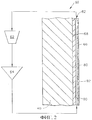
фиг.2 изображает блок-схему системы защиты от обледенения, которая использована с газотурбинным двигателем, показанным на фиг.1, согласно изобретению.figure 2 depicts a block diagram of an anti-icing system, which is used with the gas turbine engine shown in figure 1, according to the invention.
ПОДРОБНОЕ ОПИСАНИЕ ПРЕДПОЧТИТЕЛЬНОГО ВАРИАНТА ВЫПОЛНЕНИЯ ИЗОБРЕТЕНИЯDETAILED DESCRIPTION OF A PREFERRED EMBODIMENT
Газотурбинный двигатель 10 (фиг.1) содержит вентилятор 12, компрессор 14 высокого давления и камеру 16 сгорания. В одном конструктивном исполнении двигатель 10 является двигателем F110, поставляемым на рынок General Electric Company, Cincinnati, Ohio. Двигатель 10 также содержит турбину 18 высокого давления и турбину 20 низкого давления, причем все они расположены последовательно по отношению к осевому потоку. Вентилятор 12 и турбина 20 соединены первым валом 24, а компрессор 14 и турбина 18 соединены вторым валом 26.The gas turbine engine 10 (FIG. 1) comprises a fan 12, a high pressure compressor 14 and a combustion chamber 16. In one embodiment, engine 10 is an F110 engine marketed by General Electric Company, Cincinnati, Ohio. The engine 10 also comprises a high pressure turbine 18 and a low pressure turbine 20, all of which are arranged in series with respect to the axial flow. The fan 12 and the turbine 20 are connected by the first shaft 24, and the compressor 14 and the turbine 18 are connected by the second shaft 26.
Двигатель 10 также содержит кольцевую переднюю раму 40, на которую опирается подшипник (не показан), на который, в свою очередь, опирается один конец вала 24, чтобы иметь возможность вращения. Множество узлов 42 входных направляющих лопастей, расположенных по периферии с промежутками, проходят между наружным кольцом корпуса (не показан) и центральной втулкой 44 и направляют поток воздуха, входящий в двигатель 10, вниз по потоку в компрессор 14.The engine 10 also comprises an annular
При работе воздух проходит через узлы 42 входных направляющих лопастей и через вентилятор 12, так что сжатый воздух подается из вентилятора 12 в компрессор 14 высокого давления. Сильно сжатый воздух подается в камеру 16 сгорания. Поток воздуха из камеры 16 сгорания приводит в действие вращающиеся турбины 18 и 20 и выходит из газотурбинного двигателя 10. Двигатель 10 может работать в определенном диапазоне рабочих условий.During operation, air passes through the nodes 42 of the input guide vanes and through the fan 12, so that compressed air is supplied from the fan 12 to the high-pressure compressor 14. Heavily compressed air is supplied to the combustion chamber 16. The air stream from the combustion chamber 16 drives the rotating turbines 18 and 20 and exits the gas turbine engine 10. The engine 10 can operate in a certain range of operating conditions.
На фиг.2 представлена блок-схема системы 60 защиты от обледенения, которая может быть использована с газотурбинным двигателем 10. В другом конструктивном исполнении система 60 защиты от обледенения используется для того, чтобы облегчить предотвращение накопления льда вдоль открытых поверхностей (не показаны) самолета (не показан), таких как контрольная поверхность. Система 60 защиты от обледенения содержит резервуар 62 для жидкости, насос 64 для жидкости и полупроницаемую мембрану 66. В альтернативном варианте система 60 защиты от обледенения содержит механически обработанную микропористую мембрану, предпочтительнее, чем полупроницаемую мембрану 66. Полупроницаемая мембрана 66 соединена с наружной поверхностью 68 для того, чтобы облегчить предотвращение накопления льда вдоль открытых поверхностей, таких как поверхность 68. В описываемом примере полупроницаемая мембрана 66 соединена с поверхностью 68 передней кромки передней рамы 40 двигателя для того, чтобы облегчить предотвращение накопления льда на передней раме 40. Распределитель или прокладка 80 соединен с двигателем 10 между двигателем и полупроницаемой мембраной 66. Прокладка 80 обеспечивает образование зазора 82 для прохода потока между полупроницаемой мембраной 66 и поверхностью 68.2 is a block diagram of an
Насос 64 и резервуар 62 соединены по потоку друг с другом, с мембраной 66 и зазором 82, так что система 60 образует систему псевдозамкнутого контура, образованного зазором 82 и мембраной 66. Более конкретно, так как мембрана 66 является полупроницаемой, часть жидкости, циркулирующей через систему 60, проходит через мембрану 66 в процессе затекания, описанном более подробно ниже, и оставшаяся жидкость рециркулирует через систему 60. В одном варианте выполнения система 60 защиты от обледенения соединена с системой регулирования двигателя на основе процессора. Термин «процессор» относится к микропроцессорам, прикладным специальным интегральным схемам (ASIC), логическим схемам и любой другой схеме или процессору, который может управлять системой 60.A
Жидкость подается из резервуара 62 посредством насоса 64 в зазор 82. Жидкость облегчает предотвращение накопления льда на поверхности 68. Жидкость представляет собой смесь этиленгликоля или этилового спирта, в сочетании с водой, в жидком или твердом состоянии, которая воздействует либо на поверхность 68, либо на мембрану 66. Такая жидкая смесь может понизить температуру замерзания вплоть до -50oF. Эта жидкость подается в зазор 82 насосом 64, и часть жидкости диспергируется от внутренней поверхности 90 мембраны 66 на наружную поверхность 92 мембраны 66. Жидкость, диспергированная на поверхность 92, облегчает понижение температуры замерзания воды в контакте с поверхностью 92, чтобы облегчить предотвращение накопления льда на поверхности 68.The liquid is supplied from the
В другом варианте выполнения диспергирование жидкости на поверхность 92 приводит к уменьшению вязкости поверхностного слоя на поверхности 68, чтобы облегчить предотвращение накопления льда на поверхности 68. Жидкая смесь нефтяных углеводородов циркулирует внутри системы 60, чтобы облегчить уменьшение вязкости поверхностного слоя. Таким образом, система 60 облегчает повышение запаса потери скорости при срыве потока компрессора, когда двигатель работает в условиях потенциального обледенения, и таким образом облегчается предотвращение случаев сбрасывания льда в компрессор. Система 60 также облегчает предотвращение вибрации двигателя 10, которая следует за всасыванием сбрасываемого льда. Более того, так как циркуляцию жидкости внутри системы 60 не требуется производить при повышенной рабочей температуре, разнообразные материалы могут быть использованы для изготовления системы 60.In another embodiment, dispersing a liquid onto a
Описанная выше система 60 защиты от обледенения является эффективной по стоимости и высоконадежной для облегчения предотвращения накопления льда вдоль открытых поверхностей. Жидкость, подаваемая через систему, диспергируется через полупроницаемую мембрану в процессе затекания эффективным по стоимости способом. Поскольку выпускаемый воздух не используется, система защиты от обледенения облегчает предотвращение накопления льда без потерь в характеристике двигателя или без требующих высокой стоимости надувных камер. В результате система контроля обледенения облегчает повышение запаса потери скорости при срыве потока компрессора, когда двигатель работает в условиях потенциального обледенения, и таким образом исключает недостаток запаса потери скорости при срыве потока компрессора, который может иметь место в случае сбрасывания льда в компрессор, или когда двигатель используется в режиме пониженного расхода топлива.The
Claims (19)
Applications Claiming Priority (2)
| Application Number | Priority Date | Filing Date | Title |
|---|---|---|---|
| US10/188,460 | 2002-07-03 | ||
| US10/188,460 US6920748B2 (en) | 2002-07-03 | 2002-07-03 | Methods and apparatus for operating gas turbine engines |
Publications (2)
| Publication Number | Publication Date |
|---|---|
| RU2003120056A RU2003120056A (en) | 2004-12-27 |
| RU2319023C2 true RU2319023C2 (en) | 2008-03-10 |
Family
ID=29720422
Family Applications (1)
| Application Number | Title | Priority Date | Filing Date |
|---|---|---|---|
| RU2003120056/06A RU2319023C2 (en) | 2002-07-03 | 2003-07-02 | Method of operation of aircraft engine and anti-icing system (versions) |
Country Status (10)
| Country | Link |
|---|---|
| US (2) | US6920748B2 (en) |
| EP (1) | EP1378633A3 (en) |
| JP (1) | JP4555552B2 (en) |
| KR (1) | KR100836979B1 (en) |
| CN (1) | CN100520011C (en) |
| AU (1) | AU2003207033B2 (en) |
| BR (1) | BR0302379B1 (en) |
| CA (1) | CA2432841C (en) |
| RU (1) | RU2319023C2 (en) |
| ZA (1) | ZA200304719B (en) |
Cited By (1)
| Publication number | Priority date | Publication date | Assignee | Title |
|---|---|---|---|---|
| RU2815119C1 (en) * | 2023-08-07 | 2024-03-11 | федеральное государственное автономное образовательное учреждение высшего образования "Пермский национальный исследовательский политехнический университет" | Method of ice removal from aircraft engine fan blades in flight |
Families Citing this family (14)
| Publication number | Priority date | Publication date | Assignee | Title |
|---|---|---|---|---|
| US6920748B2 (en) | 2002-07-03 | 2005-07-26 | General Electric Company | Methods and apparatus for operating gas turbine engines |
| US20060204647A1 (en) * | 2005-03-09 | 2006-09-14 | Vittorio Calabrese | De-icing system for driveways, walkways, sidewalks and other surfaces |
| US7374404B2 (en) * | 2005-09-22 | 2008-05-20 | General Electric Company | Methods and apparatus for gas turbine engines |
| US7429166B2 (en) * | 2005-12-20 | 2008-09-30 | General Electric Company | Methods and apparatus for gas turbine engines |
| US20100005657A1 (en) * | 2008-07-10 | 2010-01-14 | Van Vactor David R | Methods and systems to facilitate over-speed protection |
| US8321119B2 (en) * | 2008-07-10 | 2012-11-27 | General Electric Company | Methods and systems to facilitate over-speed protection |
| US8224552B2 (en) * | 2008-07-10 | 2012-07-17 | General Electric Company | Methods and systems to facilitate over-speed protection |
| US8575900B2 (en) | 2010-09-03 | 2013-11-05 | Hamilton Sundstrand Corporation | Rotor based air gap heating for air driven turbine |
| US9422063B2 (en) * | 2013-05-31 | 2016-08-23 | General Electric Company | Cooled cooling air system for a gas turbine |
| US10156190B2 (en) * | 2015-05-20 | 2018-12-18 | Honeywell International Inc. | Gas turbine engine uncontrolled high thrust accommodation system and method |
| US10443497B2 (en) | 2016-08-10 | 2019-10-15 | Rolls-Royce Corporation | Ice protection system for gas turbine engines |
| US10801361B2 (en) | 2016-09-09 | 2020-10-13 | General Electric Company | System and method for HPT disk over speed prevention |
| US10252808B2 (en) * | 2016-09-22 | 2019-04-09 | The Boeing Company | Fluid ice protection system flow conductivity sensor |
| US11365647B2 (en) | 2020-02-28 | 2022-06-21 | Raytheon Technologies Corporation | Closed loop fan inlet vane anti icing system |
Family Cites Families (25)
| Publication number | Priority date | Publication date | Assignee | Title |
|---|---|---|---|---|
| US2075658A (en) * | 1934-04-07 | 1937-03-30 | Ramsbottom John Edwin | Ice preventing device |
| US2098566A (en) * | 1934-10-27 | 1937-11-09 | Reed Propeller Co Inc | De-icing means for aircraft |
| US2075659A (en) * | 1935-05-08 | 1937-03-30 | Ramsbottom John Edwin | Apparatus for preventing ice accumulation on aircraft |
| US2457031A (en) * | 1942-12-05 | 1948-12-21 | Borg Warner | Aircraft anti-icing arrangement |
| GB569301A (en) * | 1943-12-15 | 1945-05-16 | Pesco Products Co | Improvements in or relating to aircraft anti-icing or de-icing arrangements |
| US2390093A (en) * | 1944-03-16 | 1945-12-04 | Garrison Murray Ed | Airplane wing deicing means |
| US2812899A (en) * | 1949-08-30 | 1957-11-12 | A V Roe Canada Ltd | Intake sprinkler for gas turbine engines |
| GB724019A (en) * | 1952-07-15 | 1955-02-16 | Joseph Halbert | Improvements relating to means for distributing fluids |
| GB1094372A (en) * | 1964-04-10 | 1967-12-13 | T K S Aircraft De Icing Ltd | Improvements relating to means for distributing liquids to the surfaces of aerofoils |
| US3423052A (en) * | 1966-07-21 | 1969-01-21 | Lear Jet Ind Inc | De-icing apparatus |
| US3614038A (en) * | 1970-01-08 | 1971-10-19 | Ace Filtercraft Inc | Porous metal panel to distribute deicing fluid onto the leading edge of a surface |
| US4434201A (en) * | 1981-11-13 | 1984-02-28 | T.K.S. (Aircraft De-Icing) Limited | Porous panel |
| GB2130158A (en) * | 1982-11-15 | 1984-05-31 | Fiber Materials | Deicing aircraft surfaces |
| US5088277A (en) | 1988-10-03 | 1992-02-18 | General Electric Company | Aircraft engine inlet cowl anti-icing system |
| US5136837A (en) * | 1990-03-06 | 1992-08-11 | General Electric Company | Aircraft engine starter integrated boundary bleed system |
| US5143329A (en) * | 1990-06-01 | 1992-09-01 | General Electric Company | Gas turbine engine powered aircraft environmental control system and boundary layer bleed |
| US5125597A (en) * | 1990-06-01 | 1992-06-30 | General Electric Company | Gas turbine engine powered aircraft environmental control system and boundary layer bleed with energy recovery system |
| GB9224849D0 (en) * | 1992-11-27 | 1993-01-13 | Rolls Royce Plc | Porous structure having laminar flow control and contamination protection |
| GB2314887B (en) * | 1996-07-02 | 2000-02-09 | Rolls Royce Plc | Ice protection for porous structure |
| US6279856B1 (en) * | 1997-09-22 | 2001-08-28 | Northcoast Technologies | Aircraft de-icing system |
| US5934617A (en) * | 1997-09-22 | 1999-08-10 | Northcoast Technologies | De-ice and anti-ice system and method for aircraft surfaces |
| US6371411B1 (en) * | 1999-11-23 | 2002-04-16 | The Boeing Company | Method and apparatus for aircraft inlet ice protection |
| JP2001342849A (en) | 2000-05-31 | 2001-12-14 | Honda Motor Co Ltd | Gas turbine engine |
| US6920748B2 (en) | 2002-07-03 | 2005-07-26 | General Electric Company | Methods and apparatus for operating gas turbine engines |
| US6990797B2 (en) | 2003-09-05 | 2006-01-31 | General Electric Company | Methods and apparatus for operating gas turbine engines |
-
2002
- 2002-07-03 US US10/188,460 patent/US6920748B2/en not_active Expired - Lifetime
-
2003
- 2003-06-18 ZA ZA200304719A patent/ZA200304719B/en unknown
- 2003-06-19 CA CA2432841A patent/CA2432841C/en not_active Expired - Fee Related
- 2003-06-30 BR BRPI0302379-6A patent/BR0302379B1/en not_active IP Right Cessation
- 2003-07-01 JP JP2003189147A patent/JP4555552B2/en not_active Expired - Fee Related
- 2003-07-02 KR KR1020030044628A patent/KR100836979B1/en not_active IP Right Cessation
- 2003-07-02 EP EP03254221A patent/EP1378633A3/en not_active Withdrawn
- 2003-07-02 RU RU2003120056/06A patent/RU2319023C2/en not_active IP Right Cessation
- 2003-07-03 AU AU2003207033A patent/AU2003207033B2/en not_active Ceased
- 2003-07-03 CN CNB031453082A patent/CN100520011C/en not_active Expired - Lifetime
-
2005
- 2005-03-04 US US11/072,084 patent/US7188464B2/en not_active Expired - Lifetime
Cited By (1)
| Publication number | Priority date | Publication date | Assignee | Title |
|---|---|---|---|---|
| RU2815119C1 (en) * | 2023-08-07 | 2024-03-11 | федеральное государственное автономное образовательное учреждение высшего образования "Пермский национальный исследовательский политехнический университет" | Method of ice removal from aircraft engine fan blades in flight |
Also Published As
| Publication number | Publication date |
|---|---|
| US7188464B2 (en) | 2007-03-13 |
| US6920748B2 (en) | 2005-07-26 |
| CN1470747A (en) | 2004-01-28 |
| CA2432841C (en) | 2012-08-07 |
| BR0302379B1 (en) | 2011-11-01 |
| KR100836979B1 (en) | 2008-06-10 |
| ZA200304719B (en) | 2004-04-30 |
| JP4555552B2 (en) | 2010-10-06 |
| KR20040004134A (en) | 2004-01-13 |
| AU2003207033B2 (en) | 2010-07-22 |
| JP2004052764A (en) | 2004-02-19 |
| BR0302379A (en) | 2004-08-24 |
| CN100520011C (en) | 2009-07-29 |
| US20050039435A1 (en) | 2005-02-24 |
| EP1378633A3 (en) | 2005-11-09 |
| US20050144957A1 (en) | 2005-07-07 |
| EP1378633A2 (en) | 2004-01-07 |
| AU2003207033A1 (en) | 2004-01-22 |
| CA2432841A1 (en) | 2004-01-03 |
Similar Documents
| Publication | Publication Date | Title |
|---|---|---|
| RU2319023C2 (en) | Method of operation of aircraft engine and anti-icing system (versions) | |
| US6865891B2 (en) | Gas turbine engine | |
| US7401461B2 (en) | Reduced-weight fuel system for gas turbine engine, gas turbine engine having a reduced-weight fuel system, and method of providing fuel to a gas turbine engine using a reduced-weight fuel system | |
| US5918458A (en) | System and method of providing clean filtered cooling air to a hot portion of a gas turbine engine | |
| EP3318743B1 (en) | Intercooled cooled cooling integrated air cycle machine | |
| US4773212A (en) | Balancing the heat flow between components associated with a gas turbine engine | |
| US7134269B2 (en) | Gas turbine engine | |
| US20110088405A1 (en) | Gas turbine engine temperature modulated cooling flow | |
| US10323539B2 (en) | System and method for cleaning gas turbine engine components | |
| JP2005256840A (en) | Method and apparatus for operating gas turbine engine | |
| GB2342693A (en) | Pressure boosted compressor cooling system. | |
| US20130284398A1 (en) | Gas turbine engine thermal management system | |
| CA2982141A1 (en) | Deicing nose of an axial turbine engine compressor | |
| US20210340913A1 (en) | Fuel oxygen reduction unit with bleed driven boost impeller | |
| US20170175628A1 (en) | Method and system for inlet guide vane heating | |
| US5287694A (en) | Fluid channeling system | |
| CN113417743A (en) | Cooling system for a turbine engine | |
| RU2241844C1 (en) | Gas-turbine engine starting method | |
| US11840937B2 (en) | Diffuser nozzle for a gas turbine engine | |
| US20210341145A1 (en) | Fuel oxygen conversion unit with integrated water removal | |
| RU2133358C1 (en) | Aircraft power plant with additional gas-turbine engine for air starting system and ventilation and air-conditioning system |
Legal Events
| Date | Code | Title | Description |
|---|---|---|---|
| MM4A | The patent is invalid due to non-payment of fees |
Effective date: 20180703 |