RU2318373C1 - Sprinkler machine - Google Patents
Sprinkler machine Download PDFInfo
- Publication number
- RU2318373C1 RU2318373C1 RU2006114196/12A RU2006114196A RU2318373C1 RU 2318373 C1 RU2318373 C1 RU 2318373C1 RU 2006114196/12 A RU2006114196/12 A RU 2006114196/12A RU 2006114196 A RU2006114196 A RU 2006114196A RU 2318373 C1 RU2318373 C1 RU 2318373C1
- Authority
- RU
- Russia
- Prior art keywords
- additional
- main
- sprinkler
- brakes
- hydraulic
- Prior art date
Links
Images
Landscapes
- Braking Arrangements (AREA)
- Catching Or Destruction (AREA)
Abstract
Description
Изобретение относится к сельскому хозяйству и может быть использовано в поливной технике, а именно на дождевальных машинах, перемещающихся вокруг центральной опоры.The invention relates to agriculture and can be used in irrigation equipment, namely on sprinkler machines moving around a central support.
Известна дождевальная машина кругового действия, которая включает водопроводящий трубопровод с дождевальными аппаратами, помещенный на тележках с гидроцилиндрами (см. Краковец В.М., Никулин С.И. Справочник оператора «Фрегата» и «Волжанка», М., Колос, 1976, аналог).Known sprinkling machine circular action, which includes a water pipe with sprinklers, placed on carts with hydraulic cylinders (see Krakovets V.M., Nikulin S.I. Directory of the operator "Frigate" and "Volzhanka", M., Kolos, 1976, analogue).
Недостатком известной машины является то, что она совершает круговое движение вокруг неподвижной опоры только по часовой стрелке; что не позволяет ее использование на полях со сложной конфигурацией, где нельзя рационально вписать в них круг, а также препятствует размещению под одной машиной несколько сельскохозяйственных культур с существенно разной кратностью полива.A disadvantage of the known machine is that it makes a circular motion around a fixed support only clockwise; which does not allow its use in fields with a complex configuration, where it is not possible to rationally enter a circle in them, and also prevents the placement of several crops under a single machine with significantly different irrigation rates.
Известна также дождевальная машина, включающая неподвижную опору, самоходные тележки с гидроцилиндрами, водопроводящий трубопровод с дождевальными аппаратами, в которой для осуществления реверсивного передвижения вода попеременно подается в верхнюю и нижнюю полости гидроцилиндров, и изменена конструкция системы регулирования скорости движения тележек (Кошкин Н.М., Нагорный В.А., Гордиенко В.В., Фомин Г.И. «Фрегат» с реверсивным ходом и возможности его практического применения» ж. «Мелиорация и водное хозяйство», 2002 г., №4, прототип).Also known is a sprinkler machine, including a fixed support, self-propelled carts with hydraulic cylinders, a water supply pipe with sprinkler apparatuses, in which, for reverse movement, water is alternately supplied to the upper and lower cavities of the hydraulic cylinders, and the design of the system for controlling the speed of the carts (Koshkin N.M. , Nagorny V.A., Gordienko V.V., Fomin G.I. “Frigate” with a reverse course and the possibility of its practical application ”.“ Land Reclamation and Water Management ”, 2002, No. 4, prototype).
Недостатком этой дождевальной машины является существенное ее усложнение и удорожание, а также недостаточная надежность работы.The disadvantage of this sprinkler is its significant complication and appreciation, as well as insufficient reliability.
Технической задачей изобретения является обеспечение реверсивного передвижения, упрощение конструкции и повышение надежности работы дождевальной машины.An object of the invention is to provide reverse movement, simplifying the design and improving the reliability of the sprinkler.
Указанная задача достигается тем, что на силовом рычаге тележек закреплены кронштейны, толкатели снабжены сдвоенными наконечниками, а на основные тормоза колес приварены дополнительные тормоза с центральным углом 125°, причем каждая из тележек (кроме последней) снабжена дополнительным регулятором скорости с системой гидравлической аварийной защиты, расположенным симметрично основному регулятору скорости относительно трубопровода, причем каждый из них соединяется выходным напорным рукавом через шаровой кран с гидроцилиндром, а входным напорным рукавом - с водопроводящим трубопроводом.This task is achieved by the fact that the brackets are fixed on the power lever of the bogies, the pushers are equipped with double tips, and additional brakes with a central angle of 125 ° are welded to the main wheel brakes, and each of the bogies (except the last) is equipped with an additional speed controller with a hydraulic emergency protection system, located symmetrically to the main speed controller relative to the pipeline, each of which is connected by an output pressure hose through a ball valve to the hydraulic cylinder, and the input m hoses - a water conducting conduit.
Отличие данной дождевальной машины от прототипа заключается в том, что она комплектуется дополнительными кронштейнами силового рычага, тормозами и регуляторами скорости с гидравлической аварийной защитой, а также спаренными наконечниками толкателей. В зависимости от направления движения оператор подключает соответствующие толкатели, тормоза и регуляторы скорости. При этом существенно упрощается конструкция дождевальной машины реверсивного передвижения, повышается надежность ее работы и уменьшается стоимость работ по модернизации существующих дождевальных машин.The difference between this sprinkler machine and the prototype lies in the fact that it is equipped with additional power arm brackets, brakes and speed controllers with hydraulic emergency protection, as well as coupled pusher tips. Depending on the direction of travel, the operator connects the appropriate pushers, brakes and speed controllers. At the same time, the design of the irrigation machine of reverse movement is significantly simplified, the reliability of its operation is increased, and the cost of modernizing existing irrigation machines is reduced.
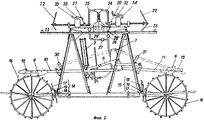
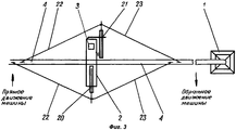
На фиг.1 показан общий вид дождевальной машины. На фиг.2 показана самоходная тележка реверсивной дождевальной машины. На фиг.3 показано расположение основного и дополнительного регуляторов скорости (вид сверху).Figure 1 shows a General view of the sprinkler. Figure 2 shows a self-propelled cart reversible sprinkler. Figure 3 shows the location of the primary and secondary speed controllers (top view).
Дождевальная машина (фиг.1) состоит из неподвижной опоры 1, самоходных тележек 2 с гидроцилиндрами 3 и водопроводящего трубопровода 4 с дождевальными аппаратами 5. На силовом рычаге 6 (фиг.2) тележки 2 закреплен кронштейн 7. Наконечники 8 и 9 переднего и заднего толкателей 10 и 11 снабжены дополнительными наконечниками 12 и 13. Стопоры 14 и 15 колес 16 снабжены основными и дополнительными тормозами 17 и 18 и пружинами 19. Причем центральный угол между основным и дополнительным тормозами составляет 125°. На тележке 2 (кроме последней) установлены основной и дополнительный регуляторы скорости 20 и 21 (фиг.3), которые при помощи тяг 22 и 23 соединены с водопроводящим трубопроводом 4. Подача воды из водопроводящего трубопровода 4 к регуляторам скорости 20 и 21 осуществляется посредством входных напорных рукавов 24 и 25. Для включения в работу основного 20 и дополнительного 21 регулятора скорости используют шаровые краны 26 и 27, которые соединяют выходные напорные рукава 28 и 29 с гидроцилиндром 3. На тележке 2 установлены дополнительные направляющие 30 и 31. На основном и дополнительном регуляторах скорости 20 и 21 смонтированы исполнительные клапаны 32 и 33 с трубками 34 и 35 гидравлической аварийной защиты.The sprinkler machine (Fig. 1) consists of a
Машина работает следующим образом. При движении машины по часовой стрелке вода под напором подается через неподвижную опору 1 в водопроводящий трубопровод 4, самоходные тележки 2 и дождевальные аппараты 5.The machine operates as follows. When the machine moves clockwise, water under pressure is supplied through a
Через входные напорные рукава 24 и 25 вода поступает в основной и дополнительный регуляторы скорости 20 и 21. Шаровой кран 27 дополнительного регулятора 21 закрыт, а шаровой кран 26 основного регулятора скорости 20 - открыт, и вода через выходной напорный рукав 28 поступает в гидроцилиндр 3. Толкатели 10 и 11 установлены на силовом рычаге 6 и при подъеме гидроцилиндра 3 передвигают колеса 16 и тележку 2 вперед. Основной тормоз 17 стопоров 14 и 15 прижимается пружинами 19 к колесу 16 и стопорит тележку 2 при холостом ходе гидроцилиндра 3. Машина вращается вокруг неподвижной опоры 1 по часовой стрелке и проводит полив поля дождевальными аппаратами 5. Безаварийную работу дождевальной машины обеспечивают исполнительные клапаны 32 и гидравлическая трубка 34 аварийной защиты основных регуляторов скорости 20.Through the
Для того чтобы дождевальная машина изменила направление движения и стала вращаться против часовой стрелки, оператор машины должен установить передние и задние толкатели 10 и 11 на кронштейн 7. При этом задний толкатель 11 разворачивается на 180° и наконечник 13 устанавливается на колесе 16. Толкатель 11 размещается в верхней направляющей 31. На переднем толкателе 10 наконечник 12 снимают и после разворота на 180° вновь монтируют на толкателе 10, который устанавливается одним концом на кронштейне 7, а другим на колесе 16. Толкатель 10 размещается в направляющей 30. Дополнительные тормоза 18 при помощи пружин 19 прижимаются к колесу 16, а основной тормоз 17 в этом положении отходит от колеса 16. Шаровой кран 26 закрывают, а шаровой кран 27 наоборот открывается, при этом вода в гидроцилиндр 3 подается через выходной напорный рукав 29 и дополнительный регулятор скорости 21. При подъеме гидроцилиндра 3 толкатели 10 и 11 передвигают тележку в обратном направлении и машина движется против часовой стрелки. Для обеспечения безаварийной работы дождевальной машины оператор отключает трубку 34 гидрозащиты основных регуляторов скорости 20 и подключает к узлу запитки гидравлическую трубку 35 дополнительных регуляторов скорости 21.In order for the sprinkler to change its direction of rotation and turn counterclockwise, the machine operator must install the front and
Предлагаемая дождевальная машина обеспечивает реверсивное движение - по часовой и против часовой стрелки, после соответствующих перестановок деталей и подключений регуляторов скорости. При этом предлагаемая машина отличается простотой конструкции, меньшей стоимостью и обеспечивает повышение надежности работы. Дождевальная машина позволяет экономить воду и энергетические ресурсы при выращивании под одной машиной нескольких сельскохозяйственных культур с различными сроками полива или одной культуры на различные нужды (зеленый корм, сено или семена). При этом исключаются дополнительные проходы по отдельным секторам поля. Кроме того, дождевальная машина может улучшить приживаемость рассады овощных культур в ранний период роста за счет улучшения водного режима почвы. Реверсивная дождевальная машина позволяет исключить поливы секторов поля с близким уровнем грунтовых вод. Возможно улучшение технологии полива орошаемых участков со сложным рельефом и с почвами низкой водопроницаемости, за счет проведения дробных поливов малыми нормами. Реверсивная дождевальная машина позволит орошать нестандартные участки, например секторные и прямоугольные, при этом повышается коэффициент земельного использования. Кроме того данная дождевальная машина позволяет оператору с меньшими трудовыми и материальными затратами и потерями сельхозпродукции провести выравнивание машины после аварийного изгиба трубопровода.The proposed sprinkler machine provides reverse movement - clockwise and counterclockwise, after the corresponding rearrangements of parts and the connection of speed controllers. At the same time, the proposed machine is characterized by simplicity of design, lower cost and provides increased reliability. Sprinkling machine allows you to save water and energy resources when growing under one machine several crops with different irrigation periods or one crop for different needs (green feed, hay or seeds). This excludes additional passes on individual sectors of the field. In addition, the sprinkler can improve the survival rate of vegetable seedlings in the early period of growth by improving the water regime of the soil. Reversible sprinkler machine eliminates irrigation of sectors of the field with a close groundwater level. It is possible to improve the irrigation technology of irrigated areas with a difficult topography and with low water permeability soils, due to fractional irrigation at low rates. Reversible sprinkler will allow irrigating non-standard areas, for example sector and rectangular, while increasing the coefficient of land use. In addition, this irrigation machine allows the operator, with less labor and material costs and agricultural losses, to level the machine after an emergency bending of the pipeline.
Дождевальная машина реверсивного передвижения внедрена в ОПХ ФГНУ «ВолжНИИГиМ» Энгельсского района.The sprinkler of reverse movement was introduced at the Volga Scientific Research Institute of Volga Research Institute of Hygiene, Engels District.
Claims (1)
Priority Applications (1)
| Application Number | Priority Date | Filing Date | Title |
|---|---|---|---|
| RU2006114196/12A RU2318373C1 (en) | 2006-04-25 | 2006-04-25 | Sprinkler machine |
Applications Claiming Priority (1)
| Application Number | Priority Date | Filing Date | Title |
|---|---|---|---|
| RU2006114196/12A RU2318373C1 (en) | 2006-04-25 | 2006-04-25 | Sprinkler machine |
Publications (2)
| Publication Number | Publication Date |
|---|---|
| RU2006114196A RU2006114196A (en) | 2007-10-27 |
| RU2318373C1 true RU2318373C1 (en) | 2008-03-10 |
Family
ID=38955601
Family Applications (1)
| Application Number | Title | Priority Date | Filing Date |
|---|---|---|---|
| RU2006114196/12A RU2318373C1 (en) | 2006-04-25 | 2006-04-25 | Sprinkler machine |
Country Status (1)
| Country | Link |
|---|---|
| RU (1) | RU2318373C1 (en) |
Cited By (4)
| Publication number | Priority date | Publication date | Assignee | Title |
|---|---|---|---|---|
| RU2378824C2 (en) * | 2008-03-18 | 2010-01-20 | ФГНУ "Волжский научно-исследовательский институт гидротехники и мелиорации" | Sprinkling machine |
| RU2410870C2 (en) * | 2008-12-29 | 2011-02-10 | Федеральное государственное научное учреждение "Волжский научно-исследовательский институт гидротехники и мелиорации" | Sprinkling machine |
| RU170892U1 (en) * | 2016-08-01 | 2017-05-12 | Федеральное государственное бюджетное научное учреждение "Волжский научно-исследовательский институт гидротехники и мелиорации" (ФГБНУ "ВолжНИИГиМ") | Sprinkler |
| RU223146U1 (en) * | 2023-11-29 | 2024-02-02 | Федеральное государственное бюджетное научное учреждение "Всероссийский научно-исследовательский институт систем орошения и сельхозводоснабжения "Радуга" (ФГБНУ ВНИИ "Радуга") | Running support of a multi-support sprinkler |
Citations (3)
| Publication number | Priority date | Publication date | Assignee | Title |
|---|---|---|---|---|
| US4735365A (en) * | 1986-10-31 | 1988-04-05 | Rain Bird Sprinkler Mfg. Corp. | Irrigation boom assembly |
| SU1625441A1 (en) * | 1988-02-29 | 1991-02-07 | Ставропольский Научно-Исследовательский Институт Гидротехники И Мелиорации | Multiple-support sprinkler |
| SU1655382A1 (en) * | 1989-04-20 | 1991-06-15 | Всесоюзное Научно-Производственное Объединение По Механизации Орошения "Радуга" | Self-propelled irrigation machine |
-
2006
- 2006-04-25 RU RU2006114196/12A patent/RU2318373C1/en not_active IP Right Cessation
Patent Citations (3)
| Publication number | Priority date | Publication date | Assignee | Title |
|---|---|---|---|---|
| US4735365A (en) * | 1986-10-31 | 1988-04-05 | Rain Bird Sprinkler Mfg. Corp. | Irrigation boom assembly |
| SU1625441A1 (en) * | 1988-02-29 | 1991-02-07 | Ставропольский Научно-Исследовательский Институт Гидротехники И Мелиорации | Multiple-support sprinkler |
| SU1655382A1 (en) * | 1989-04-20 | 1991-06-15 | Всесоюзное Научно-Производственное Объединение По Механизации Орошения "Радуга" | Self-propelled irrigation machine |
Non-Patent Citations (1)
| Title |
|---|
| КОШКИН Н.М. и др. Фрегат с реверсивным ходом и возможности его применения. - Мелиорация и водное хозяйство, №4, 2002. * |
Cited By (4)
| Publication number | Priority date | Publication date | Assignee | Title |
|---|---|---|---|---|
| RU2378824C2 (en) * | 2008-03-18 | 2010-01-20 | ФГНУ "Волжский научно-исследовательский институт гидротехники и мелиорации" | Sprinkling machine |
| RU2410870C2 (en) * | 2008-12-29 | 2011-02-10 | Федеральное государственное научное учреждение "Волжский научно-исследовательский институт гидротехники и мелиорации" | Sprinkling machine |
| RU170892U1 (en) * | 2016-08-01 | 2017-05-12 | Федеральное государственное бюджетное научное учреждение "Волжский научно-исследовательский институт гидротехники и мелиорации" (ФГБНУ "ВолжНИИГиМ") | Sprinkler |
| RU223146U1 (en) * | 2023-11-29 | 2024-02-02 | Федеральное государственное бюджетное научное учреждение "Всероссийский научно-исследовательский институт систем орошения и сельхозводоснабжения "Радуга" (ФГБНУ ВНИИ "Радуга") | Running support of a multi-support sprinkler |
Also Published As
| Publication number | Publication date |
|---|---|
| RU2006114196A (en) | 2007-10-27 |
Similar Documents
| Publication | Publication Date | Title |
|---|---|---|
| CN107466738B (en) | A kind of point control type accurate intelligent fertigation application system | |
| US4522338A (en) | Irrigation system | |
| CN105961149B (en) | The protective device of distributor supply hose and relevant fluid feed system | |
| CN2676614Y (en) | Multifunction self-walking type sprager | |
| CN202680317U (en) | Land high-amplitude-width full-automatic variable pesticide spraying machine | |
| CN106954533B (en) | Control method of intelligent garden sprinkling irrigation control system | |
| CN218042985U (en) | Automatic translation formula sprinkling irrigation machine that fixed pipeline of control supplied water | |
| US3255968A (en) | Traveling-while-sprinkling irrigation apparatus and system | |
| RU2318373C1 (en) | Sprinkler machine | |
| CN103583316A (en) | Multifunctional moving spray irrigator | |
| CN102960216A (en) | Farmland irrigation machine | |
| RU2410870C2 (en) | Sprinkling machine | |
| CN104126488A (en) | Agricultural irrigation device | |
| RU95963U1 (en) | SPRINKLER | |
| CN202680140U (en) | Movable spray irrigation equipment | |
| CN220044437U (en) | Movable irrigation machine | |
| CN206043006U (en) | Intelligent folding casting machine | |
| RU75274U1 (en) | HOSE WAITER | |
| RU160893U1 (en) | SPRINKLER | |
| CN212436781U (en) | Irrigation device | |
| RU2378824C2 (en) | Sprinkling machine | |
| RU2377766C1 (en) | Irrigation machine | |
| US9242257B2 (en) | Variable nozzle assembly | |
| CN207491895U (en) | A kind of novel orchard pesticide applicator | |
| US6029914A (en) | Corner irrigation system |
Legal Events
| Date | Code | Title | Description |
|---|---|---|---|
| MM4A | The patent is invalid due to non-payment of fees |
Effective date: 20080426 |