RU2297343C2 - Passenger car carrier - Google Patents
Passenger car carrier Download PDFInfo
- Publication number
- RU2297343C2 RU2297343C2 RU2005112809/11A RU2005112809A RU2297343C2 RU 2297343 C2 RU2297343 C2 RU 2297343C2 RU 2005112809/11 A RU2005112809/11 A RU 2005112809/11A RU 2005112809 A RU2005112809 A RU 2005112809A RU 2297343 C2 RU2297343 C2 RU 2297343C2
- Authority
- RU
- Russia
- Prior art keywords
- tier
- folding
- platform
- tracks
- possibility
- Prior art date
Links
Images
Abstract
Description
Область техники, к которой относится изобретениеFIELD OF THE INVENTION
Изобретение относится к специализированным транспортным средствам, в частности к транспортным средствам для перевозки легковых автомобилей.The invention relates to specialized vehicles, in particular to vehicles for the transport of cars.
Уровень техникиState of the art
Известно транспортное средство для перевозки шасси легковых автомобилей, содержащее несущую раму и опору под передний колесный мост перевозимого шасси, при этом на наружных боковых поверхностях рамы ниже ее опорной поверхности закреплены опоры с углублениями для задних колес перевозимых шасси, при этом первая опора установлена в передней части рамы под углом к ней консольно и направлена в сторону движения (см. а.с. СССР №998164, кл. В60Р 3/07).A vehicle for transporting a passenger car chassis is known, comprising a supporting frame and a support under the front wheel axle of the transported chassis, while supports with recesses for the rear wheels of the transported chassis are fixed on the outer side surfaces of the frame below its supporting surface, the first support being installed in front the frame at an angle to it is cantilevered and directed towards movement (see AS USSR No. 998164, class B60P 3/07).
Недостатком данного транспортного средства является недостаточная подвижность закрепления перевозимых шасси.The disadvantage of this vehicle is the lack of mobility fastening the transported chassis.
Известно устройство для крепления на транспортном средстве шасси легковых автомобилей, установленных с возможностью опирания передних колес каждого последующего автомобиля на шасси предыдущего, содержащего переднюю опору, а также опоры для задних колес перевозимых автомобилей, представляющие собой опорные площадки с трехсторонними упорами, причем на платформе закреплены продольные направляющие, к которым прикреплены все опоры, при этом передняя опора представляет собой размещенные на направляющих вдоль продольной оси транспортного средства фермы, соединенные поперечными балками, и размещенные на последних другие опорные площадки с трехсторонними упорами для передних колес первого автомобиля (см. а.с. СССР №1127785, кл. В60Р 3/07).A device for mounting on a vehicle chassis of cars installed with the possibility of supporting the front wheels of each subsequent car on the chassis of the previous one containing the front support, as well as supports for the rear wheels of transported vehicles, which are supporting platforms with three-way stops, longitudinally fixed to the platform guides to which all supports are attached, while the front support is placed on guides along the longitudinal axis of the transport o farm equipment connected by transverse beams, and placed on the other other supporting platforms with three-way stops for the front wheels of the first car (see AS USSR No. 1127785, class B60P 3/07).
Недостатком данного устройства является сложность конструкции, недостаточная подвижность закрепления перевозимых шасси.The disadvantage of this device is the design complexity, lack of mobility of the fastening of the transported chassis.
Наиболее близким по технической сущности и достигаемому положительному эффекту и принятый авторами за прототип является транспортное средство для перевозки легковых автомобилей, содержащее нижний и верхний ярусы, выполненные в виде рамы с поперечными балками и установленные на ходовую и опорную части, причем нижний ярус снабжен настилом с направляющими дорожками, расположенными параллельно основанию нижнего яруса рамы, а верхний ярус - подвижной платформой с направляющими дорожками, систему гидрооборудования, устройство для запасных колес, въездной трап, при этом оно снабжено дополнительными трапами, установленными в надседельной части нижнего яруса и состоящими из двух одинаковых частей, каждая из которых выполнена из направляющей дорожки, среднего и откидного трапов, шарнирно соединенных между собой, причем направляющие дорожки жестко закреплены на нижнем ярусе рамы, а часть настила с направляющими дорожками нижнего яруса перед откидным трапом выполнена с углублением для увеличения размера между ярусами, при этом устройство для запасных колес установлено в правой боковой части между нижнем и верхним ярусами, въездной трап выполнен в виде двух шарнирно соединенных секций с неподвижными дорожками, соединенными между собой поперечинами, причем первая секция трапа установлена с возможностью продолжения нижнего яруса, при этом в средней части первой секции установлен гидроцилиндр, шток которого шарнирно соединен с поперечным валом, снабженным захватами для фиксации первой секции трапа относительно нижнего яруса рамы, фиксирующее устройство второй секции трапа установлено на задней поперечной балке верхнего яруса и содержит гидроцилиндр, шток которого соединен тягой, снабженной крюками, соединяемыми с петлями, которые закреплены на крайней поперечине второй секции трапа, при этом с боковых сторон трапа установлены кинематические тяги, шарнирно соединенные через систему рычагов со штоками гидроцилиндров подъема-опускания трапа, причем угол наклона первой секции трапа устанавливается подвижным упором, расположенным на секции и взаимодействующим с балкой нижнего яруса, а угол наклона второй секции трапа ограничен ходом ползуна между упорами на кинематической тяге (см. пат. РФ №2149777, кл. В60Р 3/08, опубл. 27.05.2000 г.).The closest in technical essence and the achieved positive effect and adopted by the authors for the prototype is a vehicle for transporting cars, containing the lower and upper tiers, made in the form of a frame with transverse beams and mounted on the chassis and support parts, and the lower tier is equipped with a deck with guides paths parallel to the base of the lower tier of the frame, and the upper tier - a movable platform with guide tracks, hydraulic system, device for spare wheels, an entrance ladder, while it is equipped with additional ladders installed in the seatpost of the lower tier and consisting of two identical parts, each of which is made of a guide track, a middle and a folding ladder, pivotally connected to each other, and the guide tracks are rigidly fixed to the lower frame tier, and part of the deck with guide tracks of the lower tier before the folding ladder is made with a recess for increasing the size between tiers, while the device for spare wheels is installed in the right of the lateral part between the lower and upper tiers, the entry ladder is made in the form of two pivotally connected sections with fixed tracks interconnected by cross members, the first section of the ladder being installed with the possibility of continuing the lower tier, with a hydraulic cylinder installed in the middle of the first section, the rod of which pivotally connected to a transverse shaft equipped with grippers for fixing the first section of the ladder relative to the lower tier of the frame, the locking device of the second section of the ladder is mounted on the rear transverse b the upper tier and contains a hydraulic cylinder, the rod of which is connected by a rod equipped with hooks connected to loops that are fixed on the extreme cross member of the second section of the ladder, while kinematic rods are mounted on the sides of the ladder, pivotally connected through the lever system to the rods of the ram raising and lowering ramps moreover, the angle of inclination of the first section of the ladder is set by a movable stop located on the section and interacting with the beam of the lower tier, and the angle of inclination of the second section of the ladder is limited by the stroke of the slider and between the stops on the kinematic traction (see US Pat. RF №2149777, cl. B60P 3/08, publ. May 27, 2000).
Недостатком данного транспортного средства является недостаточная вместимость транспортного средства, сложность погрузки и выгрузки автомобилей.The disadvantage of this vehicle is the lack of vehicle capacity, the difficulty of loading and unloading cars.
Раскрытие изобретенияDisclosure of invention
Технический результат, который может быть достигнут с помощью предлагаемого изобретения сводится к упрощению погрузки и выгрузки автомобилей, исключая дополнительные механизмы, повышению безопасности эксплуатации и надежности закрепления перевозимых автомобилей.The technical result that can be achieved using the present invention is to simplify loading and unloading cars, excluding additional mechanisms, improving operational safety and reliability of fastening transported cars.
Технический результат достигается с помощью транспортного средства для перевозки легковых автомобилей, содержащего установленную на ходовую часть раму, имеющую нижний с настилом и верхний ярусы с поперечными балками и направляющими дорожками, причем верхний ярус снабжен подвижной платформой, а надседельная часть нижнего яруса снабжена откидными дорожками, систему гидрооборудования, въездной трап, выполненный с возможностью продолжения нижнего яруса, при этом оно снабжено двумя грузовыми платформами, двумя механизмами подъема, установленными в средней части нижнего яруса, выполненной с увеличением размера между ярусами, а надседельная часть снабжена направляющими дорожками с углублением в передней и уклоном в задней части, при этом передняя часть верхнего яруса выполнена в виде зигзагообразной поверхности с направляющими дорожками, причем на поперечной балке с возможностью подъема передней до откидных дорожек надседельной части и опускания шарнирно закреплена задняя сторона первой грузовой платформы, на передней стороне которой шарнирно закреплены захваты транспортного положения, а снизу закреплен откидной упор погрузочного положения, установленный в гнездо на поперечной балке, причем каждый механизм подъема состоит из двух одинаковых частей и выполнен в виде контурной опоры колеса, снабженной системой рычагов, один из которых регулируемый, с возможностью параллельного перемещения и исключения опрокидывания с фиксацией откидными регулируемыми упорами, а передняя сторона второй грузовой платформы шарнирно закреплена на поперечной балке с возможностью подъема задней и с фиксацией откидными регулируемыми упорами, при этом за второй платформой настил с направляющими дорожками выполнен с углублением, а въездной трап снабжен выдвижной секцией, ограничительными кронштейнами погрузочного положения, откидными регулируемыми упорами транспортного положения и погрузочными дорожками.The technical result is achieved using a vehicle for transporting cars, containing a frame mounted on the chassis, having a lower deck and upper tiers with transverse beams and guide tracks, the upper tier having a movable platform and the seat part of the lower tier having folding tracks, system hydraulic equipment, an entry ladder, made with the possibility of continuing the lower tier, while it is equipped with two cargo platforms, two lifting mechanisms, installed oval in the middle part of the lower tier, made with increasing size between the tiers, and the seatpost is equipped with guide tracks with a recess in the front and a slope in the rear part, while the front part of the upper tier is made in the form of a zigzag surface with guide tracks, and on the transverse beam with the rear side of the first cargo platform is pivotally fixed with the possibility of raising the front to the folding tracks of the seat part and lowering; sport position, and from below, a folding loading position stop is fixed, mounted in a socket on the transverse beam, each lifting mechanism consists of two identical parts and is made in the form of a contour wheel support equipped with a system of levers, one of which is adjustable, with the possibility of parallel movement and exclusion tipping with fixing with adjustable hinged stops, and the front side of the second cargo platform is pivotally mounted on the transverse beam with the possibility of lifting the rear and with locking folding and adjustable stops, while behind the second platform, the flooring with guide tracks is made with a recess, and the entrance ladder is equipped with a sliding section, restrictive arms of the loading position, folding adjustable stops of the transport position and loading tracks.
Краткое описание чертежейBrief Description of the Drawings
На фиг.1 дан общий вид транспортного средства для перевозки легковых автомобилей;Figure 1 is a General view of a vehicle for transporting cars;
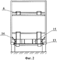
На фиг.2 - то же, вид сзади;Figure 2 is the same, rear view;
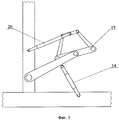
На фиг.3 - то же, механизм подъема.In Fig.3 - the same lifting mechanism.
Осуществление изобретенияThe implementation of the invention
Транспортное средство для перевозки легковых автомобилей содержит раму 1, имеющую нижний ярус 2 с настилом 3 и верхний ярус 4 с поперечными балками 5 и направляющими дорожками 6, установленную на ходовую часть 7, причем верхний ярус 4 снабжен подвижной платформой 8, а передняя часть выполнена в виде зигзагообразной поверхности с направляющими дорожками 6.The vehicle for transporting cars contains a frame 1 having a lower tier 2 with a deck 3 and an upper tier 4 with transverse beams 5 and
Надседельная часть нижнего яруса 2 снабжена направляющими дорожками 6 с углублениями (не показано) в передней части, уклоном (не показано) и откидными дорожками 9 в задней части.The seatpost of the lower tier 2 is provided with
В задней части яруса 2 с возможностью его продолжения установлен въездной трап 10, подъем и опускание которого осуществляется с помощью системы гидрооборудования 11, причем въездной трап 10 оборудован выдвижной секцией 12, ограничительными кронштейнами для погрузочного положения 13, откидными регулируемыми упорами 14 для фиксации транспортного положения и на въездном трапе 10 закреплены погрузочные дорожки 15; в средней части нижнего яруса 2, которая выполнена с увеличением размера между ярусами 2, 4, на поперечной балке 5 с возможностью подъема передней до откидных дорожек 9 надседельной части и опускания, шарнирно закреплена задняя сторона первой грузовой платформы 16, на передней стороне которой шарнирно закреплены захваты (не показано) транспортного положения, а снизу закреплен откидной упор 17 погрузочного положения, установленный в гнездо (не показано) на поперечной балке 5, два механизма подъема 18, причем каждый состоит из двух одинаковых частей и выполнен в виде контурной опоры колеса 19, снабженной системой рычагов 20, один из которых регулируемый, с возможностью параллельного перемещения и исключения опрокидывания, подъем и опускание которых осуществляется с помощью системы гидрооборудования 11 и с фиксацией в транспортном положении откидными регулируемыми упорами 14, а передняя сторона второй грузовой платформы 21 шарнирно закреплена на поперечной балке 5 с возможностью подъема задней с помощью системы гидрооборудования 11 и с фиксацией откидными регулируемыми упорами 14, при этом за второй грузовой платформой 21 настил 3 с направляющими дорожками 6 выполнен с углублением (не показан).In the back of the tier 2, with the possibility of its continuation, an entry ladder 10 is installed, the raising and lowering of which is carried out using a hydraulic system 11, and the entrance ladder 10 is equipped with a sliding section 12, restrictive brackets for the
Транспортное средство для перевозки легковых автомобилей эксплуатируется следующим образом.A vehicle for transporting cars is operated as follows.
Транспортное средство, установленное на ходовую часть 7, загружается следующим образом. С помощью системы гидрооборудования 11, въездной трап 10, освобожденный от откидных регулируемых упоров 14, погрузочных дорожек 15 с выдвижной секцией 12 опускается до упора ограничительных кронштейнов 13 в нижнем ярусе 2 и опускается подвижная платформа 8, при этом первый автомобиль заезжает задним ходом по трапу 10 с выдвижной секцией 12, подвижной платформе 8 на зигзагообразную поверхность верхнего яруса 4, затем второй, третий и четвертый автомобили заезжают обычным ходом и производится подъем подвижной платформы 8. Перед погрузкой нижнего яруса 2 необходимо вторую погрузочную платформу 21 опустить и погрузочными дорожками 15 закрыть углубление настила 3 с направляющими дорожками 6 за второй грузовой платформой 21, затем поднять первую грузовую платформу 16 до откидных дорожек 9 надседельной части нижнего яруса 2, при этом откидной упор 17, установленный снизу платформы 16, должен попасть в гнездо на поперечной балке 5. Пятый автомобиль заезжает своим ходом по въездному трапу 10 с выдвижной секцией 12, по погрузочным дорожкам 15, по второй грузовой платформе 21, по настилу 3 с направляющими дорожками 6, по контурным опорам колес 19 механизмов подъема 18, по первой грузовой платформе 16, откидным дорожкам 9 на надседельную часть нижнего яруса 2 таким образом, чтобы передние колеса автомобиля попали в углубления, а задние стали на уклоне, затем откидные дорожки 9 поднимаются вверх, откидной упор 17 убирается и первая грузовая платформа 16 опускается в транспортное положение и фиксируется захватами. Шестой автомобиль заезжает задним ходом таким образом, чтобы передние колеса автомобиля попали в контурные опоры колес 19 механизмов подъема 18 и через систему рычагов 20 производится подъем передней части автомобиля до верхнего яруса 4. Механизмы подъема 18 фиксируются откидными регулируемыми упорами 14. Седьмой автомобиль заезжает таким образом, чтобы задние колеса попали в контурные опоры колес 19 второго механизма подъема 18, причем передняя часть автомобиля заезжает под приподнятый шестой автомобиль, производится подъем автомобиля аналогично предыдущему. Восьмой автомобиль заезжает таким образом, чтобы передняя часть была под приподнятой задней частью седьмого автомобиля, а задние колеса на второй погрузочной платформе 21, которая затем поднимается и фиксируется откидными регулируемыми упорами 14. Погрузочные дорожки 15 закрепляются на въездном трапе 10. Девятый автомобиль заезжает таким образом, чтобы его передние колеса попали в углубление настила 3, а задние остались на въездном трапе 10. Трап 10 поднимается, выдвижная секция 12 убирается и трап 10 фиксируется откидными регулируемыми упорами 14. Разгрузка в обратном порядке.The vehicle mounted on the chassis 7 is loaded as follows. Using the hydraulic system 11, the entry ladder 10, freed from the adjustable hinge stops 14, the
Предлагаемое изобретение по сравнению с прототипом и другими известными техническими решениями имеет следующее преимущества:The invention in comparison with the prototype and other known technical solutions has the following advantages:
- упрощение погрузки и выгрузки автомобилей, исключая дополнительные механизмы;- simplification of loading and unloading vehicles, excluding additional mechanisms;
- повышение безопасности эксплуатации;- increase operational safety;
- повышение надежности закрепления перевозимых автомобилей;- improving the reliability of securing transported vehicles;
- исключение ручного труда при фиксации въездного трапа в транспортном положении, неподвижной и грузовых платформ.- the exception of manual labor when fixing the entry ladder in the transport position, fixed and cargo platforms.
Claims (1)
Priority Applications (1)
| Application Number | Priority Date | Filing Date | Title |
|---|---|---|---|
| RU2005112809/11A RU2297343C2 (en) | 2005-04-27 | 2005-04-27 | Passenger car carrier |
Applications Claiming Priority (1)
| Application Number | Priority Date | Filing Date | Title |
|---|---|---|---|
| RU2005112809/11A RU2297343C2 (en) | 2005-04-27 | 2005-04-27 | Passenger car carrier |
Publications (2)
| Publication Number | Publication Date |
|---|---|
| RU2005112809A RU2005112809A (en) | 2006-11-10 |
| RU2297343C2 true RU2297343C2 (en) | 2007-04-20 |
Family
ID=37500439
Family Applications (1)
| Application Number | Title | Priority Date | Filing Date |
|---|---|---|---|
| RU2005112809/11A RU2297343C2 (en) | 2005-04-27 | 2005-04-27 | Passenger car carrier |
Country Status (1)
| Country | Link |
|---|---|
| RU (1) | RU2297343C2 (en) |
Cited By (1)
| Publication number | Priority date | Publication date | Assignee | Title |
|---|---|---|---|---|
| RU194452U1 (en) * | 2019-11-06 | 2019-12-11 | Александр Викторович Токарский | DEVICE FOR CARRIAGE OF WHEELED VEHICLES |
-
2005
- 2005-04-27 RU RU2005112809/11A patent/RU2297343C2/en not_active IP Right Cessation
Cited By (1)
| Publication number | Priority date | Publication date | Assignee | Title |
|---|---|---|---|---|
| RU194452U1 (en) * | 2019-11-06 | 2019-12-11 | Александр Викторович Токарский | DEVICE FOR CARRIAGE OF WHEELED VEHICLES |
Also Published As
| Publication number | Publication date |
|---|---|
| RU2005112809A (en) | 2006-11-10 |
Similar Documents
| Publication | Publication Date | Title |
|---|---|---|
| US6099232A (en) | Device for loading a small vehicle or other load onto a pickup truck | |
| RU2709690C2 (en) | Lifting assembly (embodiments), user vehicle and method of removing flooring from lifting assembly | |
| US4627784A (en) | Loading and unloading apparatus for a vehicle | |
| US20110202199A1 (en) | Cargo Loading and Unloading System for a Vehicle | |
| JPS61166740A (en) | Automobile transport car with independent support structure exclusive for each axle | |
| US20090025154A1 (en) | Vehicle And Equipment Hauler Attachment For Pickup Trucks | |
| RU2741659C2 (en) | Transport platform | |
| US6485237B1 (en) | Double-deck trailer | |
| KR20180016171A (en) | A trailer for car transport | |
| US20090026785A1 (en) | Truck bed assembly with integral partial sliding deck with pivoting inclined towers for raising and lowering a sliding deck | |
| US3724698A (en) | Goods vehicles | |
| UA51843C2 (en) | Support and positioning unit of a hinged aggregate for vehicles transportation | |
| US9132763B2 (en) | Loading and unloading system for a vehicle | |
| RU2297343C2 (en) | Passenger car carrier | |
| US2993725A (en) | Automobile trailer | |
| RU65439U1 (en) | VEHICLE FOR CARRYING PASSENGER CARS | |
| CN108407903B (en) | Van-type transport vehicle with movable and replaceable van body | |
| RU2368517C1 (en) | Transport vehicle for transportation of trucks and self-mobile machines | |
| RU76863U1 (en) | SEMITRAILER FOR CAR TRANSPORTATION | |
| RU76608U1 (en) | SEMITRAILER FOR CAR TRANSPORTATION | |
| RU91697U1 (en) | SEMITRAILER FOR CAR TRANSPORTATION | |
| JP4153701B2 (en) | Cargo handling equipment | |
| RU2299138C2 (en) | Universal car carrier | |
| RU91698U1 (en) | SEMITRAILER FOR CAR TRANSPORTATION | |
| US20080226435A1 (en) | Loading and unloading apparatus for trailer body |
Legal Events
| Date | Code | Title | Description |
|---|---|---|---|
| MM4A | The patent is invalid due to non-payment of fees |
Effective date: 20100428 |