RU2260647C2 - Paver for laying road pavement layers - Google Patents
Paver for laying road pavement layers Download PDFInfo
- Publication number
- RU2260647C2 RU2260647C2 RU2002130442/03A RU2002130442A RU2260647C2 RU 2260647 C2 RU2260647 C2 RU 2260647C2 RU 2002130442/03 A RU2002130442/03 A RU 2002130442/03A RU 2002130442 A RU2002130442 A RU 2002130442A RU 2260647 C2 RU2260647 C2 RU 2260647C2
- Authority
- RU
- Russia
- Prior art keywords
- cylinders
- laying
- stacker
- stacker according
- support cylinders
- Prior art date
Links
Images

Classifications
-
- E—FIXED CONSTRUCTIONS
- E01—CONSTRUCTION OF ROADS, RAILWAYS, OR BRIDGES
- E01C—CONSTRUCTION OF, OR SURFACES FOR, ROADS, SPORTS GROUNDS, OR THE LIKE; MACHINES OR AUXILIARY TOOLS FOR CONSTRUCTION OR REPAIR
- E01C19/00—Machines, tools or auxiliary devices for preparing or distributing paving materials, for working the placed materials, or for forming, consolidating, or finishing the paving
- E01C19/22—Machines, tools or auxiliary devices for preparing or distributing paving materials, for working the placed materials, or for forming, consolidating, or finishing the paving for consolidating or finishing laid-down unset materials
- E01C19/30—Tamping or vibrating apparatus other than rollers ; Devices for ramming individual paving elements
- E01C19/34—Power-driven rammers or tampers, e.g. air-hammer impacted shoes for ramming stone-sett paving; Hand-actuated ramming or tamping machines, e.g. tampers with manually hoisted dropping weight
- E01C19/40—Power-driven rammers or tampers, e.g. air-hammer impacted shoes for ramming stone-sett paving; Hand-actuated ramming or tamping machines, e.g. tampers with manually hoisted dropping weight adapted to impart a smooth finish to the paving, e.g. tamping or vibrating finishers
-
- E—FIXED CONSTRUCTIONS
- E01—CONSTRUCTION OF ROADS, RAILWAYS, OR BRIDGES
- E01C—CONSTRUCTION OF, OR SURFACES FOR, ROADS, SPORTS GROUNDS, OR THE LIKE; MACHINES OR AUXILIARY TOOLS FOR CONSTRUCTION OR REPAIR
- E01C2301/00—Machine characteristics, parts or accessories not otherwise provided for
- E01C2301/14—Extendable screeds
- E01C2301/16—Laterally slidable screeds
Landscapes
- Engineering & Computer Science (AREA)
- Architecture (AREA)
- Civil Engineering (AREA)
- Structural Engineering (AREA)
- Road Paving Machines (AREA)
- Road Paving Structures (AREA)
- Body Structure For Vehicles (AREA)
Abstract
Description
Изобретение относится к укладчику для укладки слоев дорожного покрытия, содержащему ходовую часть и шарнирно связанный с ней через тяговые кронштейны плавающий укладочный брус, угол установки которого по отношению к грунту регулируется исполнительными цилиндрами и который содержит основной брус и выдвижные брусья и/или пристраиваемые части бруса, причем предусмотрены цилиндры транспортирования укладочного бруса.The invention relates to a stacker for laying pavement layers, comprising a running gear and a floating laying beam pivotally connected to it via traction brackets, the installation angle of which with respect to the soil is regulated by the executive cylinders and which contains the main beam and extendable bars and / or attached parts of the beam, moreover, cylinders for transporting the laying beam are provided.
Известно прокладывание слоев, например, в строительстве дорог, укладчиком с так называемыми плавающими укладочными брусьями. Укладочный брус при этом с помощью находящихся вне рамы или, соответственно, ходовой части укладчика тяговых кронштейнов шарнирно установлен по середине укладчика, т.е. с возможностью тяги и перемещения по высоте. Укладочный брус сам плавает на подлежащем укладке слое материала с положительным углом установки, т.е. лежащая впереди по направлению хода укладчика кромка укладочного бруса находится в более высокой позиции, чем задняя кромка. Положительный угол установки получается из таких параметров, как несущая способность смеси, степени трамбовочного и вибрационного уплотнения, веса укладочного бруса, скорости укладки и т.д.Laying of layers is known, for example, in road construction, by a stacker with so-called floating laying beams. In this case, the stacking beam is pivotally mounted in the middle of the stacker using the traction arms outside the frame or, accordingly, the chassis of the stacker, i.e. with the possibility of traction and movement in height. The laying beam itself floats on the layer of material to be laid with a positive installation angle, i.e. the edge of the stacking bar lying in front of the direction of travel of the stacker is in a higher position than the trailing edge. A positive installation angle is obtained from such parameters as the bearing capacity of the mixture, the degree of tamper and vibration compaction, the weight of the laying beam, the laying speed, etc.
Этот положительный угол установки, а также, в частности, дозировочный скос трамбовки, находящейся в передней зоне укладочного бруса, представляют собой, если смотреть в направлении хода, "рампы". Эти "рампы", однако, при достаточно высокой температуре смеси сдавливаются с помощью уплотняющих элементов, таких, как, по меньшей мере, одна трамбовка и один вибрационный агрегат, а также за счет веса укладочного бруса на такое значение по высоте, которое задается задней кромкой укладочного бруса, что также называется уплотнением. Если же, например, вследствие перерыва в укладке, лежащий под укладочным брусом и перед трамбовкой материал охлаждается, то в результате он намного хуже поддается уплотнению.This positive installation angle, as well as, in particular, the metering bevel of the rammer located in the front area of the stacking beam, are “ramps” when viewed in the direction of travel. These "ramps", however, at a sufficiently high temperature, the mixture is compressed using sealing elements, such as at least one rammer and one vibrating unit, as well as due to the weight of the laying beam by a height value set by the trailing edge laying timber, also called compaction. If, for example, due to a break in laying, the material lying under the laying beam and before tamping cools, then as a result it is much less resistant to compaction.
Вследствие этого при возобновлении хода укладчика укладочный брус на рампах отклоняется вверх и только после достижения смеси с нормальной температурой опять занимает положение с лежащей на более низком уровне заданной высотой. Возникающие перед возобновлением укладки бугры оказываются тем выше, чем дольше длится перерыв для загрузки и вместе с этим дольше действует эффект охлаждения.As a result of this, when the stacker resumes its course, the laying beam on the ramps deviates upward and only after reaching a mixture with a normal temperature again occupies a position with a predetermined height lying at a lower level. The hillocks arising before resuming laying turn out to be the higher, the longer the break for loading lasts, and with this the cooling effect lasts longer.
Кроме того, образованию подобных бугров способствует, например, применение высоко уплотняющих укладочных брусов и/или применение жесткого битума, что в настоящее время имеет наибольшее распространение.In addition, the formation of such bumps is facilitated, for example, by the use of highly sealing laying beams and / or the use of hard bitumen, which is currently the most common.
Эти возникающие перед возобновлением хода бугры представляют собой неровности, которые частично выступают значительно выше допускаемых неровностей. Поэтому пытаются устранить эти бугры ручным образом с помощью граблей и т.п. Наряду с высокими затратами ручным устранением бугров не обеспечивается ровность, которая может достигаться безупречно работающим укладчиком.These hillocks arising before resuming travel are irregularities that partially protrude significantly higher than the allowed irregularities. Therefore, they try to eliminate these hillocks manually using a rake, etc. Along with the high costs, manual removal of the hillocks does not ensure evenness, which can be achieved by a perfectly working stacker.
В процессе укладки укладочный брус, шарнирно прикрепленный к укладчику по его середине, тянется им и изменяет свою высоту. Находящиеся в задней зоне укладчика цилиндры транспортирования, которые в случае транспортирования приподнимают укладочный брус, находятся во время процесса укладки в безнапорном, т.е. не влияющем на положение по высоте укладочного бруса состоянии. Эти цилиндры транспортирования укладочных брусьев со стороны своих поршней укреплены на верхней задней раме укладчика, а своими штоковыми сторонами на связанных с укладочным брусом тяговых кронштейнах.In the process of laying, the laying beam, pivotally attached to the stacker in its middle, is pulled by it and changes its height. The transport cylinders located in the rear area of the stacker, which, in the case of transportation, lift the stacking beam, are in a pressureless, i.e. not affecting the height position of the laying beam. These cylinders for transporting the laying beams on the side of their pistons are mounted on the upper rear frame of the stacker, and with their rod ends on the traction arms connected to the laying beam.
Для предотвращения образования бугров цилиндры транспортирования укладочных брусьев блокируются на несколько секунд в момент возобновления хода укладчика, так что укладочный брус не может отклоняться вверх, так как укладчик противодействует этому своим весом. Продолжительность блокировки выбирается таким образом, что обеспечивается преодоление укладчиком зоны лежащей под укладочным брусом и перед трамбовкой холодной смеси материала.To prevent the formation of bumps, the cylinders for transporting the stacking beams are blocked for several seconds at the moment the stacker resumes movement, so that the stacking bar cannot deviate upwards, as the stacker counteracts this by its weight. The blocking duration is selected in such a way that the stacker overcomes the zone lying under the laying beam and before tamping the cold mixture of material.
В связи с тем, что цилиндры транспортирования укладочного бруса, в зависимости от базовой ширины укладчика, находятся внутри диапазона 2,5, соответственно, 3,0 м, действие так называемого арретира подъема бруса в средней зоне укладочного бруса является удовлетворительным, однако, вследствие эластичности укладочного бруса является неудовлетворительным во внешней зоне. В этой связи следует учитывать то, что выдвижной укладочный брус имеет рабочую ширину до 9,0 м, а пристраиваемый вручную укладочный брус имеет в настоящее время ширину более 13 м.Due to the fact that the cylinders for transporting the laying beam, depending on the base width of the stacker, are within the range of 2.5, respectively, 3.0 m, the effect of the so-called arrester lifting the beam in the middle zone of the laying beam is satisfactory, however, due to the elasticity The laying beam is unsatisfactory in the outer zone. In this regard, it should be borne in mind that the retractable laying beam has a working width of up to 9.0 m, and the manually attached laying beam has at present a width of more than 13 m.
При пристраиваемом вручную укладочном брусе пытаются увеличить вертикальную жесткость укладочного бруса, например, посредством лежащих поверх укладочного бруса опор. Это удается, однако, только частично, так как вследствие большой ширины опорные усилия недостаточны, чтобы обеспечить действие арретира подъема бруса также и во внешней зоне бруса.With a manually mounted laying beam, they try to increase the vertical stiffness of the laying beam, for example, by means of supports lying on top of the laying beam. This is possible, however, only partially, because, due to the large width, the supporting forces are insufficient to ensure the action of the beam lifting arrester also in the outer zone of the beam.
Однако, особенно критичной является ситуация при выдвижных укладочных брусьях. Как известно, находящиеся позади основного бруса выдвижные расширяющие брус части (называемые также выдвижные брусья) выдвигаются гидравлически и по потребности расширяются с помощью пристраиваемых вручную удлинений до 9,0 м. Действие арретира подъема бруса по отношению к основному брусу также и здесь является удовлетворительным. Однако оно четко снижается уже вследствие люфта и эластичности в направляющем механизме укладочных брусьев, к тому же в этой зоне нельзя предусматривать опорные элементы, как это можно применять для пристраиваемых вручную укладочных брусьев. Даже, если бы это и можно было осуществить, этого было бы недостаточно.However, the situation is especially critical with retractable laying beams. As you know, the retractable expanding beam parts located behind the main beam (also called extendable beams) are hydraulically extendable and, if necessary, can be expanded with manually adjustable extensions up to 9.0 m.The effect of the arrester on raising the beam with respect to the main beam is also satisfactory here. However, it is clearly reduced already due to backlash and elasticity in the guiding mechanism of the laying beams; moreover, supporting elements cannot be provided in this zone, as it can be used for manually placed laying beams. Even if this could be done, it would not be enough.
Указанные недостатки присущи и раскрытому в DE 19821090 A1 укладчику для прокладки слоев дорожного покрытия, содержащему ходовую часть и шарнирно связанный с ней через тяговые кронштейны плавающий укладочный брус, угол установки которого по отношению к грунту регулируется исполнительными цилиндрами и который содержит основной брус и выдвижные брусья и/или пристраиваемые части бруса, причем предусмотрены цилиндры транспортирования укладочного бруса.These drawbacks are also inherent in the stacker for laying pavement layers disclosed in DE 19821090 A1, comprising a running gear and a pivotally connected floating stacker bar, the installation angle of which with respect to the ground is regulated by the actuating cylinders and which contains the main beam and extendable bars and / or attached parts of the beam, and cylinders for transporting the laying beam are provided.
Задачей изобретения является разработка такого укладчика вышеописанного типа, при котором предотвращается образование бугров в начале хода также и во внешних зонах бруса или, по меньшей мере, оно может быть снижено настолько, что высота бугров будет лежать в допустимых границах и не потребуется дополнительной обработки.The objective of the invention is to develop such a stacker of the type described above, which prevents the formation of bumps at the beginning of the course also in the outer zones of the beam or, at least, it can be reduced so that the height of the bumps will lie within acceptable limits and will not require additional processing.
Эта задача в укладчике для прокладки слоев дорожного покрытия, содержащем ходовую часть и шарнирно связанный с ней через тяговые кронштейны плавающий укладочный брус, угол установки которого по отношению к грунту регулируется исполнительными цилиндрами и который содержит основной брус и выдвижные брусья и/или пристраиваемые части бруса, причем предусмотрены цилиндры транспортирования укладочного бруса, согласно изобретению решается тем, что поперек к направлению движения расположен, по меньшей мере, один связанный с одной стороны с задней по направлению прокладки зоной ходовой части и с другой стороны с выдвижными брусьями и/или пристраиваемыми частями бруса каждой стороны гидравлический опорный цилиндр, причем опорные цилиндры в момент начала хода укладчика нагружены регулируемым гидравлическим давлением в направлении к грунту.This task is in a stacker for laying pavement layers containing a running gear and a floating laying beam pivotally connected to it via traction brackets, the installation angle of which with respect to the soil is regulated by the executive cylinders and which contains the main beam and extendable bars and / or attached parts of the beam, moreover, cylinders for transporting the laying beam are provided, according to the invention, it is decided that at least one connected on one side with The bottom in the direction of the laying by the running gear zone and, on the other hand, with sliding beams and / or attached parts of the beams of each side, is a hydraulic support cylinder, and the support cylinders are loaded with adjustable hydraulic pressure towards the ground at the moment the stacker starts to move.
Опорные цилиндры шарнирно закреплены с поршневой стороны на ходовой части, а со штоковой стороны шарнирно закреплены на выдвижном брусе или, соответственно, на пристраиваемой части бруса.The supporting cylinders are pivotally mounted on the piston side on the undercarriage, and on the rod side, pivotally mounted on a retractable beam or, accordingly, on an attached part of the beam.
Опорные цилиндры шарнирно соединены через предусмотренную на поршневой и штоковой стороне точку и обеспечивающий достаточный люфт шарнирный подшипник.The support cylinders are pivotally connected through a point provided on the piston and rod side and providing a sufficient clearance of the articulated bearing.
Ходовая часть снабжена подвесками для опорных цилиндров.The chassis is equipped with suspensions for the supporting cylinders.
Подвески для опорных цилиндров включают консоли.Suspension brackets for support cylinders include consoles.
Опорные цилиндры шарнирно закреплены на внешних стенках выдвижного бруса и/или пристраиваемых частей бруса.The supporting cylinders are pivotally mounted on the outer walls of the extendable beam and / or attached parts of the beam.
Ход опорных цилиндров при имеющемся выдвижном брусе имеет достаточную величину, обеспечивающую свободное от помех расширение бруса.The stroke of the support cylinders with the existing retractable beam is of sufficient size to ensure that the beam is free from interference.
Опорные цилиндры шарнирно установлены с соблюдением допустимой ширины транспортирования укладчика.The support cylinders are pivotally mounted in compliance with the permissible width of the stacker transportation.
Опорные цилиндры выполнены в виде плунжерных цилиндров.The supporting cylinders are made in the form of plunger cylinders.
Опорные цилиндры выполнены в виде цилиндров двойного действия.The supporting cylinders are made in the form of double acting cylinders.
Нагрузка давлением опорных цилиндров выполнена с возможностью регулировки.The pressure load of the support cylinders is adjustable.
Настройка нагрузки давлением опорных цилиндров сблокирована с ходовым приводом таким образом, что она действует выборочно при останове укладчика или при начале его хода.The pressure setting of the pressure of the support cylinders is interlocked with the travel drive in such a way that it acts selectively when the stacker stops or when it starts to move.
Длительность нагрузки давлением опорных цилиндров регулируема.The duration of the pressure load of the support cylinders is adjustable.
Настройка нагрузки давлением опорных цилиндров осуществляется вручную.Manually adjusting the pressure load of the support cylinders.
Нагрузка давлением опорных цилиндров регулируема таким образом, что укладочный брус занимает плавающее положение как при включенной, так и при выключенной нагрузке давлением.The pressure load of the support cylinders is adjustable so that the laying beam occupies a floating position both when the pressure is on and off.
Укладочный брус включает, по меньшей мере, одну трамбовку и одну выглаживающую пластину.The stacking beam includes at least one tamper and one smoothing plate.
Укладочный брус включает, по меньшей мере, одну вибрационную выглаживающую пластину.The stacking beam includes at least one vibrating smoothing plate.
В задней зоне укладчика поверх укладочного бруса размещаются на каждой стороне по одному гидравлическому цилиндру таким образом, что он располагается поперек к направлению хода укладчика, связан со стороны поршня с ходовой частью, а со стороны поршневого штока с расширяющими брус частями. В частности, в связи с выдвижными брусьями соединение со стороны поршневого штока во внешней зоне имеющейся для регулирования ширины направляющей рамы происходит таким образом, что регулировка ширины может производиться по всей ширине без ограничения из-за опорной функции.In the rear zone of the stacker, one hydraulic cylinder is placed on top of the stacking bar on each side so that it is transverse to the direction of travel of the stacker, connected from the piston to the chassis, and from the piston rod to the parts that expand the beam. In particular, in connection with the extendable bars, the connection from the side of the piston rod in the outer zone of the width of the guide frame available for adjusting is such that the width can be adjusted over the entire width without restriction due to the support function.
В противоположность арретиру подъема бруса опорные цилиндры в момент начала хода не блокируются с поршневой стороны, а нагружаются регулируемым гидравлическим давлением. Эти меры необходимы вследствие взаимодействия с арретиром подъема бруса, а также увеличением размера поперек к направлению хода и дают следующие преимущества:In contrast to the cantilever, the support cylinders are not blocked on the piston side at the moment of the start of the stroke, but are loaded with adjustable hydraulic pressure. These measures are necessary due to the interaction with the bearer lifting the beam, as well as an increase in size across the direction of travel and give the following advantages:
- возможна регулировка давления нагрузки в соответствии с рабочей шириной;- it is possible to adjust the load pressure in accordance with the working width;
- возможно относительное движение поперек к направлению хода между укладчиком и укладочным брусом, вызванное, например, поворотом руля в момент начала хода;- possible relative movement across to the direction of travel between the stacker and the laying beam, caused, for example, by turning the steering wheel at the start of the stroke;
- наезды, например, передней ходовой части укладчика на лежащую перед ним смесь материала не приводят к вдавливанию укладочного бруса в смесь;- collisions, for example, of the front chassis of the stacker with the mixture of material lying in front of it, do not lead to the indentation of the laying beam into the mixture;
- точечная регулировка тяги в начале хода возможна в любой момент.- precise adjustment of traction at the beginning of the stroke is possible at any time.
Расположенные, в основном, поперек к направлению хода укладчика гидравлические цилиндры соединяются с укладочным брусом таким образом, что приложение их усилия происходит в задней части бруса и этим создается противодействие происходящему при укладывании скручиванию укладочного бруса.Hydraulic cylinders located mainly across the direction of travel of the stacker are connected to the stacking beam in such a way that their efforts are applied to the rear of the beam and this creates a counteraction to the twisting of the stacking beam when laying.
Другие формы выполнения изобретения вытекают из нижеследующего описания и зависимых пунктов формулы изобретения.Other forms of carrying out the invention result from the following description and dependent claims.
Далее изобретение поясняется на основе следующих чертежей, которые изображают:The invention is further explained on the basis of the following drawings, which depict:
Фиг.1 - вид сбоку укладчика.Figure 1 is a side view of the stacker.
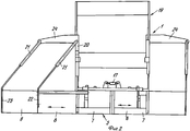
Фиг.2 - вид укладчика сзади справа без выдвинутого бруса и слева с выдвинутым выдвижным брусом.Figure 2 is a rear view of the stacker on the right without an extended beam and on the left with an extended retractable beam.
Фиг.3 - гидравлическую схему нагрузки опорных цилиндров.Figure 3 is a hydraulic load diagram of the support cylinders.
Представленный в нерабочем состоянии укладчик для укладки слоев дорожного покрытия и т.п. включает ходовую часть 1 с гусеничными ходовыми механизмами 2 (вместо этого могут быть предусмотрены колеса), причем ходовая часть 1 с передней стороны имеет ковш 3 и с задней стороны распределительный шнек 4, между которыми расположен (не виден) транспортер для транспортировки подлежащей укладке смеси из ковша 3 по транспортной шахте, над которой находятся кузовные элементы, в зону распределительного шнека 4.Inoperative stacker for laying pavement layers, etc. includes a running gear 1 with caterpillar running gears 2 (wheels can be provided instead), the running gear 1 having a bucket 3 on the front side and a distribution screw 4 on the rear side, between which a conveyor is located (not visible) for transporting the mixture to be laid from bucket 3 along the transport shaft, above which there are body elements, into the zone of the distribution screw 4.
К ходовой части 1 шарнирно через тяговые кронштейны 6 присоединен плавающий укладочный брус 5 для плавающей укладки смеси материала. Укладочный брус 5 находится в направлении укладки позади зоны распределительного шнека 4 и может содержать основной брус 7, а также выдвигаемые относительно него с боков и независимо друг от друга выдвижные брусья 8. Основной брус 7 обычно разделен по середине, причем обе половины основного бруса 7 для установки углового профиля с помощью соответствующих установочных устройств 17 поперек к направлению укладки наклонены друг к другу. Посредством выдвижных брусьев 8 основной брус 7 может устанавливаться на двойную ширину. Если выдвижных брусьев 8 не имеется или нужно произвести дополнительное расширение, это осуществляется с помощью пристраиваемых вручную по частям элементов 9 бруса. Выдвижные брусья 8 или, соответственно, пристраиваемые элементы 9 бруса в общем смещены на одну глубину бруса относительно основного бруса 7 в направлении укладки.To the chassis 1 pivotally through the traction arms 6 is attached a floating laying
Каждый тяговый кронштейн 6 шарнирно соединен своим передним концом с ходовой частью 1 с возможностью поворота, причем точка воздействия шарнира может быть смещена по высоте относительно ходовой части 1. Это осуществляется, например, за счет того, что тяговый кронштейн 6 на своем переднем конце выполнен вилкообразно, своим вилкообразным концом охватывает плоскую металлическую пластину 10 и через подшипниковое кольцо расположенного в точке 11 на вилкообразном конце, принимающего тяговые усилия подшипника опирается на плоскую металлическую пластину 10, в то время как исполнительный цилиндр 12 взаимодействует с вилкообразным концом и для изменения высоты укладываемого материала или, соответственно, для нивелирования, устанавливает высоту точки воздействия шарнира по отношению к ходовой части 1, вследствие чего оказывает влияние на подлежащий положительной регулировке угол установки укладочного бруса 5 по отношению к грунту 14.Each traction arm 6 is pivotally connected with its front end to the chassis 1, and the impact point of the hinge can be shifted in height relative to the chassis 1. This is done, for example, due to the fact that the traction bracket 6 is forked at its front end , with its fork-shaped end, covers a flat metal plate 10 and, through a bearing ring located at a point 11 on a fork-shaped end, which receives the traction forces of the bearing, rests on a flat metal plate 10, while the actuating cylinder 12 interacts with a fork-shaped end and to change the height of the material to be laid or, accordingly, for leveling, sets the height of the point of impact of the hinge with respect to the chassis 1, as a result of which it affects the installation angle of the laying
Цилиндры 13 транспортирования бруса служат для приподнимания укладочного бруса 5 в положение транспортирования. Оно находится в случае укладки в плавающем положении, не считая вышеописанный случай возобновления хода укладчика.The cylinders 13 for transporting the beam are used to raise the stacking
При прокладке материала цилиндры 13 транспортирования бруса могут применяться для частичного снятия нагрузки на брус за счет того, что они передают часть веса укладочного бруса 5 на ходовую часть 1. При укладке менее несущеспособного материала за счет арретирования бруса цилиндрами 13 вызывается опускание укладочного бруса 5 во время простоя укладчика. Посредством блокировки транспортных цилиндров 13 со стороны поршня можно предотвращать приподнимание укладочного бруса при возобновлении хода, т.е. практически они воздействуют на основной брус 7, как описано выше.When laying the material, the cylinders 13 for transporting the beam can be used to partially relieve the load on the beam due to the fact that they transfer part of the weight of the
Для получения ровных слоев материала в поперечном профиле (без углового профиля или с ним) задние кромки основного бруса 7 и задние кромки выдвижных брусьев 8 должны находиться друг относительно друга на одной высоте, а именно независимо от того, прокладывается ли материал с угловым профилем или с поперечным уклоном. В соответствии с этим выдвижные брусья 8 могут регулироваться по высоте по отношению к основному брусу 7. Изменения угла установки должны компенсироваться соответствующими изменениями регулировки для сохранения гладкой укладки дорожного покрытия.To obtain even layers of material in the transverse profile (without or with an angular profile), the rear edges of the
Основной брус 7 содержит (так же как и выдвижные брусья 8) с нижней стороны в качестве уплотняющего инструмента, по меньшей мере, одну перемещаемую с помощью не показанного привода вверх и вниз на заданный ход, снабженную дозировочным скосом трамбовочную планку 16, а также связанную с не показанным вибрационным приводом разглаживающую плиту 18. Привод трамбовочной планки (или планок) 16 выполнен, в частности, в виде эксцентрикового привода и может регулироваться в зависимости от числа трамбовочных планок 16. Кузовные элементы ходовой части 1 включают кабину управления 19, которая сбоку сзади снабжена цилиндровыми подвесками 20 для шарнирного соединения с поршневой стороны с проходящими сбоку наружу гидравлическими цилиндрами 21, в то время как со стороны поршневых штоков они шарнирно соединены с внешними стенками 22 или, соответственно, 23 укладочного бруса 8 или, соответственно, пристроенных частей 9. Шарнирное соединение осуществляется, по меньшей мере, при имеющихся выдвижных брусьях 8, например, через шарнирные подшипники, соответственно шаровые шарниры, которые имеют достаточный люфт, так что они не мешают гидравлическому расширению бруса за счет выдвигания выдвижных брусьев 8. Соответственно большим должен быть ход гидравлических цилиндров 21, чтобы они без демонтажа обеспечивали всевозможные перемещения бруса относительно укладчика.The
По меньшей мере, один гидравлический цилиндр 21 расположен на каждой стороне укладчика 21 и нагружает при гидравлической нагрузке соответствующую половину бруса, в основном, по вертикали. При большой рабочей ширине, при которой применяются выдвижные брусья 8 и пристроенные части 9 бруса, опорные цилиндры 21, взаимодействующие с пристроенными частями 9 бруса, могут быть шарнирно соединены с выступающими наружу в задней зоне укладчика консолями 24. Опорные цилиндры 21, в противоположность к арретиру подъема бруса, не блокированы с поршневой стороны исполнительными цилиндрами 12 в момент возобновления хода, а нагружены регулируемым гидравлическим давлением.At least one
Подвески 20 цилиндров на ходовой части 1 и на укладочном брусе 5 размещены целесообразным образом так, что допустимая ширина транспортирования для укладчика с задвинутым выдвижным брусом 8 не превышает 2,55 или, соответственно, 3 м.Suspensions of 20 cylinders on the running gear 1 and on the
В качестве гидравлических цилиндров пригодны, в частности, плунжерные цилиндры, в то время как применяемое для их нагрузки гидравлическое давление можно регулировать. При этом целесообразно связывать регулировку нагрузки давлением гидравлических цилиндров 21 с ходовым приводом таким образом, чтобы она действовала частично уже при останове укладчика или только при начале хода. Длительность действия может также регулироваться. Кроме того, целесообразно синхронизировать регулировку нагрузки давлением гидравлических цилиндров 21 с имеющимся при основной ширине арретиром подъема бруса. В случае необходимости регулировка нагрузки давлением гидравлических цилиндров 21 может осуществляться вручную.In particular, plunger cylinders are suitable as hydraulic cylinders, while the hydraulic pressure used to load them can be adjusted. In this case, it is advisable to associate the pressure control of the pressure of the
Нагрузка давлением осуществляется при этом таким образом, что плавающий режим работы укладочного бруса 5, т.е. относительное движение укладочного бруса 5 к укладчику в вертикальном направлении сохраняется как при включенной, так и при выключенной нагрузке давлением.In this case, pressure loading is carried out in such a way that the floating mode of operation of the
При применении гидравлических цилиндров 21 двойного действия через них можно производить разгрузку расширяющих брус частей, например, при прокладке материала с плохой несущей способностью.When using
Фиг.3 показывает гидравлический цикл для привода опорных цилиндров 21. При этом предусмотрен приводимый двигателем 25, например, дизельным двигателем укладчика, гидравлический насос 26. Таким насосом может быть насос, который снабжает и другие гидравлические агрегаты, или же отдельный насос. Гидравлический насос 26 подает гидравлическую жидкость из резервуара 27 через четырех- двухходовой клапан 28 к опорным цилиндрам 21, причем в представленном положении четырех- двухходового клапана 28 опорные цилиндры 21 не нагружены давлением, т.е. связаны с резервуаром 27, так же как и включающий гидравлический цилиндр 26 контур. Кроме того, предусмотрен регулируемый электрически или вручную, настроенный, например, на максимальное давление в 50 бар клапан 29 ограничения давления.Figure 3 shows the hydraulic cycle for driving the
Четырех- двухходовым клапаном 28 можно управлять электрически через ходовой привод укладчика, так что при возобновлении хода (или уже при останове) укладчика производится переключение, и опорные цилиндры 21 нагружаются давлением. Эта нагрузка давлением сохраняется с помощью не показанного, управляемого ходовым приводом при возобновлении хода реле времени для заданного, в случае необходимости регулируемого времени, например, в 5 или 10 секунд. После этого клапан 28 снова занимает показанное на фиг.3 положение, так что опорные цилиндры 21 больше не нагружаются давлением.The four-
Claims (17)
Applications Claiming Priority (2)
| Application Number | Priority Date | Filing Date | Title |
|---|---|---|---|
| DE10155507A DE10155507B4 (en) | 2001-11-13 | 2001-11-13 | Finisher for the bottom-side installation of layers for roads od. Like. |
| DE10155507.5 | 2001-11-13 |
Publications (2)
| Publication Number | Publication Date |
|---|---|
| RU2002130442A RU2002130442A (en) | 2004-05-20 |
| RU2260647C2 true RU2260647C2 (en) | 2005-09-20 |
Family
ID=7705467
Family Applications (1)
| Application Number | Title | Priority Date | Filing Date |
|---|---|---|---|
| RU2002130442/03A RU2260647C2 (en) | 2001-11-13 | 2002-11-12 | Paver for laying road pavement layers |
Country Status (10)
| Country | Link |
|---|---|
| US (1) | US6932538B2 (en) |
| EP (1) | EP1310598B1 (en) |
| JP (1) | JP3834794B2 (en) |
| CN (1) | CN1419009B (en) |
| AT (1) | ATE401458T1 (en) |
| CA (1) | CA2411602C (en) |
| DE (2) | DE10155507B4 (en) |
| DK (1) | DK1310598T3 (en) |
| ES (1) | ES2307700T3 (en) |
| RU (1) | RU2260647C2 (en) |
Cited By (1)
| Publication number | Priority date | Publication date | Assignee | Title |
|---|---|---|---|---|
| CN110438869A (en) * | 2018-05-02 | 2019-11-12 | 卡特彼勒路面机械公司 | Leveling part towing point component for paver |
Families Citing this family (19)
| Publication number | Priority date | Publication date | Assignee | Title |
|---|---|---|---|---|
| US20050058507A1 (en) * | 2003-09-17 | 2005-03-17 | Cedarapids, Inc. | Multi-use paving tractor with tool attachments |
| US20070065230A1 (en) * | 2003-09-17 | 2007-03-22 | Cedarapids, Inc. | Self Propelled Remix Machine with Conveyor |
| US7458747B2 (en) * | 2003-09-17 | 2008-12-02 | Cedarapids, Inc. | Frame raising multi-use paving tractor with blind mateable quick connecting tool attachments |
| US7198429B2 (en) * | 2004-03-31 | 2007-04-03 | Fabcon, Inc. | Segmented concrete screed |
| CA2582210A1 (en) * | 2006-03-22 | 2007-09-22 | Cedarapids, Inc. | Multi-stage modular road paving equipment and method of manufacture and sales |
| EP2218824B1 (en) * | 2009-02-16 | 2012-12-26 | Joseph Vögele AG | Screed |
| DE102009019839A1 (en) † | 2009-03-09 | 2010-09-16 | Bomag Gmbh | Hydraulic control arrangement for the screed of a road paver |
| DE502009000291D1 (en) * | 2009-05-25 | 2011-02-24 | Joseph Voegele Ag | Paver and process |
| EP2256247B2 (en) * | 2009-05-25 | 2017-08-09 | Joseph Vögele AG | Finisher |
| JP5089670B2 (en) * | 2009-10-16 | 2012-12-05 | 住友建機株式会社 | Screed telescopic device for paving machine |
| EP3138961B1 (en) | 2009-11-20 | 2018-08-22 | Joseph Vögele AG | Paving screed |
| DE202010012456U1 (en) * | 2010-09-10 | 2011-12-12 | Smg Sportplatzmaschinenbau Gmbh | Ready-to-install with a storage container |
| US8529152B1 (en) * | 2012-03-28 | 2013-09-10 | Caterpillar Paving Products Inc. | Resistive braking via screed heating |
| DE102012206857A1 (en) * | 2012-04-25 | 2013-10-31 | Leonhard Weiss Gmbh & Co. Kg | Device for clamping screed of road finisher, has locking unit that is designed as pressure switch for limiting the pressure generated by material template, if material supplied to material template is not uniform |
| CN102720117B (en) * | 2012-06-27 | 2015-01-07 | 中联重科股份有限公司 | Screed plate and paver |
| CN102852078A (en) * | 2012-08-18 | 2013-01-02 | 徐州凯莫尔重工科技有限公司 | Mechanism for fixing front stretch oil cylinder of retractable screed plate |
| US9200415B2 (en) * | 2013-11-19 | 2015-12-01 | Caterpillar Paving Products Inc. | Paving machine with automatically adjustable screed assembly |
| CN111648211A (en) * | 2020-06-10 | 2020-09-11 | 陕西建设机械股份有限公司 | Telescopic screed plate lengthening support device and construction method |
| CN113152222B (en) * | 2021-04-13 | 2022-11-29 | 徐州工业职业技术学院 | Ironing plate suitable for small paver |
Family Cites Families (12)
| Publication number | Priority date | Publication date | Assignee | Title |
|---|---|---|---|---|
| FR1337936A (en) * | 1962-08-27 | 1963-09-20 | Jaeger Machine Co | Leveling and material distribution machine for road widening |
| US3891338A (en) * | 1973-04-30 | 1975-06-24 | Barber Greene Co | Convergent link system for connecting a screed to the traction unit of a paving machine |
| US4147448A (en) * | 1977-05-25 | 1979-04-03 | The South African Inventions Development Corporation | Method of operating a compaction roller assembly, and a compaction roller assembly |
| DE3535362C1 (en) * | 1985-10-03 | 1987-03-26 | Joseph Voegele Ag | Method and device for adjusting the height of a leveling screed |
| DE4211286C2 (en) * | 1992-04-03 | 2003-08-21 | Metso Dynapac Gmbh | Method for locking a paving stone of a paver and paver for carrying out the method |
| DE9406683U1 (en) * | 1994-04-21 | 1994-06-30 | Joseph Vögele AG, 68163 Mannheim | Paver |
| IT1276147B1 (en) * | 1995-11-16 | 1997-10-27 | Niarb S A | ROAD PAVER WITH AUTOMATIC HEIGHT CONTROL OF THE TRANSVERSAL AUGERS WITH RESPECT TO THE SCREEN |
| DE19605148C1 (en) * | 1996-02-13 | 1997-07-31 | Abg Allg Baumaschinen Gmbh | Road building surfacing vehicle |
| DE19739687C1 (en) * | 1997-09-10 | 1999-04-08 | Abg Allg Baumaschinen Gmbh | Paver |
| DE19833394C1 (en) * | 1998-07-24 | 1999-09-30 | Abg Allg Baumaschinen Gmbh | Board mounting for road making vehicle |
| EP1120495A1 (en) * | 2000-01-25 | 2001-08-01 | Joseph Vögele AG | Paver |
| DE10036784C1 (en) * | 2000-07-28 | 2001-09-20 | Abg Allg Baumaschinen Gmbh | Tamping board, for road builder, has base board and retractable board part connected by hydraulically-operated clamps and having height-adjustment unit with rotating spindles |
-
2001
- 2001-11-13 DE DE10155507A patent/DE10155507B4/en not_active Expired - Lifetime
-
2002
- 2002-11-08 CN CN021503826A patent/CN1419009B/en not_active Expired - Lifetime
- 2002-11-11 DE DE50212500T patent/DE50212500D1/en not_active Expired - Lifetime
- 2002-11-11 AT AT02025023T patent/ATE401458T1/en active
- 2002-11-11 EP EP02025023A patent/EP1310598B1/en not_active Expired - Lifetime
- 2002-11-11 ES ES02025023T patent/ES2307700T3/en not_active Expired - Lifetime
- 2002-11-11 DK DK02025023T patent/DK1310598T3/en active
- 2002-11-12 CA CA002411602A patent/CA2411602C/en not_active Expired - Fee Related
- 2002-11-12 RU RU2002130442/03A patent/RU2260647C2/en not_active IP Right Cessation
- 2002-11-12 US US10/292,049 patent/US6932538B2/en not_active Expired - Lifetime
- 2002-11-13 JP JP2002329155A patent/JP3834794B2/en not_active Expired - Fee Related
Cited By (1)
| Publication number | Priority date | Publication date | Assignee | Title |
|---|---|---|---|---|
| CN110438869A (en) * | 2018-05-02 | 2019-11-12 | 卡特彼勒路面机械公司 | Leveling part towing point component for paver |
Also Published As
| Publication number | Publication date |
|---|---|
| CA2411602C (en) | 2007-01-23 |
| JP2003184024A (en) | 2003-07-03 |
| JP3834794B2 (en) | 2006-10-18 |
| DK1310598T3 (en) | 2008-11-10 |
| ES2307700T3 (en) | 2008-12-01 |
| US20030113166A1 (en) | 2003-06-19 |
| CN1419009B (en) | 2011-10-26 |
| DE50212500D1 (en) | 2008-08-28 |
| CA2411602A1 (en) | 2003-05-13 |
| EP1310598A2 (en) | 2003-05-14 |
| DE10155507A1 (en) | 2003-05-28 |
| EP1310598B1 (en) | 2008-07-16 |
| US6932538B2 (en) | 2005-08-23 |
| ATE401458T1 (en) | 2008-08-15 |
| EP1310598A3 (en) | 2004-03-03 |
| CN1419009A (en) | 2003-05-21 |
| DE10155507B4 (en) | 2005-10-06 |
Similar Documents
| Publication | Publication Date | Title |
|---|---|---|
| RU2260647C2 (en) | Paver for laying road pavement layers | |
| US6238135B1 (en) | Paver having adjustable screed angle using a tamper bar | |
| US8118316B2 (en) | Operational methods for a road-building machine | |
| CN109914204B (en) | Road finisher with pivoting material deflector | |
| US5599135A (en) | Asphalt spreader | |
| RU2002130442A (en) | STACKER FOR LAYING ROAD COATS AND ETC. | |
| US6352386B2 (en) | Road finisher having a laying beam with automatically adjustable extendable beams | |
| CN201778260U (en) | Spreading machine for wide pavement | |
| US4432672A (en) | Canal building apparatus | |
| CA1138258A (en) | Self-propelled ballast cleaning machine | |
| CN101545238A (en) | Novel paver | |
| CN1113090A (en) | Tiltable hood assembly for an earth working machine | |
| JPH10114910A (en) | Self-propelled concrete finisher | |
| EP0774542B1 (en) | Road paver-finisher with automatic control of the height of the transverse augers with respect to the screed | |
| CN101575839A (en) | Novel traction type spreading machine | |
| RU2263175C2 (en) | Additional device for road finishing machine | |
| JPH07102521A (en) | Screed device for paving machine and the like | |
| CN101545239A (en) | Novel paver | |
| CN112888822B (en) | Asphalt rolling machine | |
| US11585049B2 (en) | Overload support system for a paving machine screed assembly | |
| US8256986B2 (en) | Machine for paving concrete paths | |
| US3891338A (en) | Convergent link system for connecting a screed to the traction unit of a paving machine | |
| JPH01304205A (en) | Roadbed finishing machine | |
| CN201400846Y (en) | Novel push type spreading machine | |
| EP0753626A1 (en) | Surfacing apparatus |
Legal Events
| Date | Code | Title | Description |
|---|---|---|---|
| MM4A | The patent is invalid due to non-payment of fees |
Effective date: 20181113 |