EP1310598B1 - Paver for laying roadlayers - Google Patents
Paver for laying roadlayers Download PDFInfo
- Publication number
- EP1310598B1 EP1310598B1 EP02025023A EP02025023A EP1310598B1 EP 1310598 B1 EP1310598 B1 EP 1310598B1 EP 02025023 A EP02025023 A EP 02025023A EP 02025023 A EP02025023 A EP 02025023A EP 1310598 B1 EP1310598 B1 EP 1310598B1
- Authority
- EP
- European Patent Office
- Prior art keywords
- screed
- paver
- paver according
- supporting cylinders
- cylinders
- Prior art date
- Legal status (The legal status is an assumption and is not a legal conclusion. Google has not performed a legal analysis and makes no representation as to the accuracy of the status listed.)
- Expired - Lifetime
Links
Images


Classifications
-
- E—FIXED CONSTRUCTIONS
- E01—CONSTRUCTION OF ROADS, RAILWAYS, OR BRIDGES
- E01C—CONSTRUCTION OF, OR SURFACES FOR, ROADS, SPORTS GROUNDS, OR THE LIKE; MACHINES OR AUXILIARY TOOLS FOR CONSTRUCTION OR REPAIR
- E01C19/00—Machines, tools or auxiliary devices for preparing or distributing paving materials, for working the placed materials, or for forming, consolidating, or finishing the paving
- E01C19/22—Machines, tools or auxiliary devices for preparing or distributing paving materials, for working the placed materials, or for forming, consolidating, or finishing the paving for consolidating or finishing laid-down unset materials
- E01C19/30—Tamping or vibrating apparatus other than rollers ; Devices for ramming individual paving elements
- E01C19/34—Power-driven rammers or tampers, e.g. air-hammer impacted shoes for ramming stone-sett paving; Hand-actuated ramming or tamping machines, e.g. tampers with manually hoisted dropping weight
- E01C19/40—Power-driven rammers or tampers, e.g. air-hammer impacted shoes for ramming stone-sett paving; Hand-actuated ramming or tamping machines, e.g. tampers with manually hoisted dropping weight adapted to impart a smooth finish to the paving, e.g. tamping or vibrating finishers
-
- E—FIXED CONSTRUCTIONS
- E01—CONSTRUCTION OF ROADS, RAILWAYS, OR BRIDGES
- E01C—CONSTRUCTION OF, OR SURFACES FOR, ROADS, SPORTS GROUNDS, OR THE LIKE; MACHINES OR AUXILIARY TOOLS FOR CONSTRUCTION OR REPAIR
- E01C2301/00—Machine characteristics, parts or accessories not otherwise provided for
- E01C2301/14—Extendable screeds
- E01C2301/16—Laterally slidable screeds
Definitions
- the invention relates to a paver for the bottom-side installation of layers for roads or the like. according to the preamble of claim 1.
- US 4,759,657 A is a paver with a floating screed known.
- the connection between the screed and the paver produce booms which are each attached laterally to the paver with their free end.
- At the rear end of the finisher attacking lifting cylinders are also arranged in the vicinity of the screed on the jibs.
- roadway material is brought in the direction of travel in front of the screed, from which the screed forms a layer of desired thickness by stripping and compacting.
- the screed thus moves floating on the road building material, supported by the lift cylinders open in both directions.
- the screed together with the arms and the lifting cylinders forms a rigidly connected to the paver system that allows no height changes.
- the screed can then not necessarily be raised by road construction material, which has arrived in front of the screed before the standstill of the road construction machine and has lost flowability during standstill. A height error in the layer is thus avoided.
- the screed which is articulated via traction arms and tie points in the middle of the paver, pulled by this and changed their altitude.
- Bohlenentransportzylinder located in the rear paver area which lift the screed for transport, are during the installation process in an unpressurized, ie the height of the screed not influencing state.
- These screed transport cylinders are fastened with their piston side to the upper rear frame of the paver and with their piston rod side to the pulling arms connected to the screed.
- the screed transport cylinder is blocked at the moment of restarting for a few seconds piston side, so that the screed can not dodge upwards, since now the paver holds with his weight against it.
- the period of locking is sized to ensure that the paver has overcome the area of the cold mix below the screed and before the rammer.
- extendable screeds As is known, here are located behind the base screed extendable Bohlenverbreiterungsmaschine (also called extendable) hydraulically extended and expanded according to the need by manually attachable extensions up to 9.0 m. The mode of action of the screed ramp with respect to the base pile is also satisfactory here. However, it is already characterized by play and elasticity Guide mechanism of the extension boards significantly minimized, especially in this area no supports can be brought as in the manually attachable screeds in application. Even if this happens, as already mentioned with the manually installable screeds, this would not be enough.
- the object of the invention is to provide a paver according to the preamble of claim 1, avoided with the Anfahrbuckel in the outer plank area or at least can be minimized to the extent that they are within the tolerance range and require no further treatment.
- the actuating cylinders which are provided according to the invention for avoiding the Anfahrbuckels, transversely to the direction of travel of the finisher and disposed substantially outside of the chassis, wherein they piston side with the chassis and piston rod side with the outer sides, i. the outer cheeks are connected to the Bohlenverbreiteronne formed by the Ausfahrbohlen and / or pieced screed parts.
- piston side In the rear paver area above the screed per side at least one hydraulic cylinder is arranged such that it is transverse to the direction of travel, piston side is connected to the chassis and piston rod side with Bohlenverbreiterungsutz.
- piston rod side connection takes place in the outer region of the guide frame available for the width adjustment, in such a way that the width adjustment over the entire range can be carried out without restriction by the support function.
- the hydraulic cylinders arranged essentially transversely to the direction of travel are connected to the screed in such a way that their introduction of force takes place in the rear plank area and thus positively counteracts the rotation of the screed during installation.
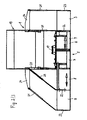
- Fig. 1 shows a side view of a paver.
- Fig. 2 shows a rear view of the paver right without and left with extended extension screed.
- Fig. 3 shows a hydraulic circuit diagram for a Stauerzylinderbeetzwegung.
- the paver shown in the non-working state for the bottom-side installation of layers of roads or the like. includes a chassis 1 with crawler tracks 2 (instead, can also be provided bogies), the chassis 1 on the front of a bucket 3 and the rear a distributor screw 4, between which a (not visible) conveyor for transporting mix to be incorporated from the bucket 3 by a Delivery shaft, over which structures are located in the area of the distributor screw 4 is arranged.
- a floating screed 5 is articulated for floating installation of Constant mix via tension arms 6.
- the screed 5 is located in the installation direction behind the area of the auger 4 and may comprise a base pile 7 and with respect to this laterally and independently extendable Ausfahrbohlen 8.
- the base screed 7 is usually divided in the middle, wherein the two halves of the base screed 7 for adjusting a roof profile via a corresponding adjusting device 17 transversely to the installation direction are mutually tilted.
- the extension boards 8 the base pile 7 is broadened to about twice its width. If no extension boards 8 are present or if an additional broadening is to be made, this is done by means of manually attachable screed parts 9.
- the extension boards 8 and the attachable screed parts 9 are generally offset by a screed depth relative to the base screed 7 in the installation direction.
- Each pull arm 6 is pivoted at its front end on the chassis 1, wherein the pivot point relative to the chassis 1 is height adjustable. This is effected, for example, that the tension arm 6 is forked at its front end, with its forked end a flat iron 10 engages and is arranged on a bearing ring of a arranged at 11 in the bifurcated end, the tensile forces receiving bearing on the flat iron 10, while an actuating cylinder 12 engages the forked end and determines the height of the articulation point with respect to the chassis 1 for the purpose of the change in thickness or leveling, whereby a positively adjusted angle of attack of the screed 5 relative to the substrate 14 is affected.
- Screed transport cylinder 13 serve to raise the screed 5 in transport position. These are in the installation case, apart from the case initially described when restarting the paver, generally in floating position.
- the base screed 7 comprises (as well as the extension boards 8) in particular at the bottom as compression tools at least one on a drive not shown up to a predeterminable stroke up and down movable, provided with a Dosageschräge tamper strip 16 and subsequently an optionally coupled with a vibration drive not shown smoothing plate 18th
- the drive of the tamper strip (s) 16 is designed in particular as an eccentric drive and with respect to the number of strokes of the tamper strip (s) 16 adjustable.
- the superstructures of the chassis 1 include a driver's cab 19 laterally provided with cylinder suspensions 20 for laterally outwardly extending hydraulic cylinders 21 on the piston side, while being hinged on outer cheeks 22 and 23, respectively, of the extension boards 8 and the staked board parts 9, respectively are.
- the articulation takes place at least for existing extension boards 8, for example, via spherical plain bearings or ball joints, which have sufficient clearance, so that the hydraulic Boom broadening by extending the extension boards 8 is not affected. Accordingly large, the stroke of the hydraulic cylinder 21 has to be so that they are fair without dismantling all screed adjustments relative to the paver.
- At least one hydraulic support cylinder 21 is arranged on each side of the paver and loaded at hydraulic loading the respective screed half substantially vertically.
- Ausfahrbohlen 8 and piezied screed parts 9 may be hinged to the latter attacking support cylinder 21 in the rear paver area laterally outwardly projecting arms 24.
- the support cylinder 21 are not blocked on the piston side in contrast to Pohlenaufsteigarret réelle by the screed transport cylinder 13 at the moment of startup, but acted upon by an adjustable hydraulic pressure.
- the cylinder suspensions 20 on the chassis 1 and on the screed 5 are suitably mounted so that the permissible transport width for the paver with retracted extension boards 8 of 2.55 m and 3 m is not exceeded.
- hydraulic pressure used for their application is preferably adjustable. It is also expedient if the control of the pressurization of the hydraulic cylinder 21 is locked to the traction drive so that it is either already effective when stopping the paver or only when starting. The duration of effectiveness can also be designed adjustable. In addition, it is expedient to synchronize the control of the pressurization with the existing in the base width screed lift arrest. Optionally, the control of the pressurization according to the need also be done manually.
- the pressurization is designed so that the floating behavior (floating) of the screed 5, ie relative movements of the screed 5 opposite the paver is maintained in the vertical direction, both on and off pressurized.
- Fig. 3 shows a hydraulic circuit for actuating the support cylinder 21.
- a motor 25 such as the diesel engine of the paver, driven hydraulic pump 26 is provided.
- the latter may be a pump which also provides for other hydraulic power units or may be a separate pump.
- the hydraulic pump 26 delivers hydraulic fluid from a reservoir 27 via a 4-2-way valve 28 to the support cylinders 21, wherein in the illustrated position of the 4-2-way valve 28, the support cylinder 21 unencumbered, ie with the reservoir 27 as well as the hydraulic pump 26th associated circle are connected.
- an electrically or manually adjustable for example, set to a maximum pressure of 50 bar pressure relief valve 29 is provided.
- the 4-2-way valve 28 is electrically controlled via the drive of the paver, so that when restarting (or even when stopping) the paver is switched, so that the support cylinders 21 are pressurized. This pressurization is maintained (not shown) via a time relay triggered by the travel drive when restarting for a predetermined, optionally adjustable time of, for example, 5 or 10 sec. Thereafter, the 4-2-way valve 28 takes in Fig. 3 shown position again, so that the support cylinder 21 are no longer pressurized.
Landscapes
- Engineering & Computer Science (AREA)
- Architecture (AREA)
- Civil Engineering (AREA)
- Structural Engineering (AREA)
- Road Paving Machines (AREA)
- Road Paving Structures (AREA)
- Body Structure For Vehicles (AREA)
Abstract
Description
Die Erfindung betrifft einen Fertiger zum bodenseitigen Einbau von Schichten für Straßen od.dgl. nach dem Oberbegriff des Anspruchs 1.The invention relates to a paver for the bottom-side installation of layers for roads or the like. according to the preamble of claim 1.
Aus
Während des Einbauvorgangs wird die Einbaubohle, die über Zugarme und Zugpunkte mittig an den Fertiger angelenkt ist, von diesem gezogen und in ihrer Höhenlage verändert. Im hinteren Fertigerbereich befindliche Bohlentransportzylinder, die für den Transportfall die Einbaubohle anheben, befinden sich während des Einbauvorganges in einem drucklosen, d.h. die Höhenlage der Einbaubohle nicht beeinflussenden Zustand. Diese Bohlentransportzylinder sind mit ihrer Kolbenseite am oberen hinteren Rahmen des Fertigers und mit ihrer Kolbenstangenseite an den mit der Einbaubohle verbundenen Zugarmen befestigt.During the installation process, the screed, which is articulated via traction arms and tie points in the middle of the paver, pulled by this and changed their altitude. Bohlenentransportzylinder located in the rear paver area, which lift the screed for transport, are during the installation process in an unpressurized, ie the height of the screed not influencing state. These screed transport cylinders are fastened with their piston side to the upper rear frame of the paver and with their piston rod side to the pulling arms connected to the screed.
Um Anfahrbuckeln entgegenzuwirken, wird der Bohlentransportzylinder im Moment des Wiederanfahrens für einige Sekunden kolbenseitig gesperrt, so daß die Einbaubohle nicht nach oben hin ausweichen kann, da nunmehr der Fertiger mit seinem Gewicht dagegen hält. Die Zeitdauer des Sperrens wird so bemessen, daß sichergestellt ist, daß der Fertiger den Bereich des unter der Einbaubohle und vor dem Stampfer liegenden kalten Mischguts überwunden hat.To counteract Anfahrbuckeln, the screed transport cylinder is blocked at the moment of restarting for a few seconds piston side, so that the screed can not dodge upwards, since now the paver holds with his weight against it. The period of locking is sized to ensure that the paver has overcome the area of the cold mix below the screed and before the rammer.
Da die Bohlentransportzylinder sich jedoch je nach Grundbreite des Fertigers innerhalb von 2,5 bzw. 3,0 m befinden, ist die Wirkung der sogenannten Bohlenaufsteigarretierung im mittleren Bereich einer Einbaubohle zufriedenstellend, jedoch aufgrund der Elastizität der Einbaubohlen nicht im äußeren. Man beachte in diesem Zusammenhang, daß ausfahrbare Einbaubohlen Arbeitsbreiten bis 9,0 m und manuell anbaubare Einbaubohlen bis z.T. über 13 m aufweisen.However, since the screed transport cylinders are within 2.5 and 3.0 m depending on the basic width of the paver, the effect of the so-called screed ramp in the middle region of a screed is satisfactory, but not in the outer due to the elasticity of screeds. It should be noted in this context that extendable screeds working widths up to 9.0 m and manually attachable screeds to z.T. over 13 m.
Bei manuell anbaubaren Einbaubohlen wird z.B. durch oberhalb der Einbaubohle liegende Stützen versucht, die vertikale Steifigkeit der Einbaubohle in sich zu vergrößern. Dieses gelingt jedoch nur zum Teil, da aufgrund der großen Bohlenbreite die Stützkräfte nicht ausreichend groß sind, um die Wirkung der Bohlenaufsteigarretierung auch im äußeren Bohlenbereich sicher zu stellen.For manually buildable screeds, e.g. Supports above the screed seek to increase the vertical stiffness of the screed. However, this succeeds only in part, since due to the large plank width, the supporting forces are not large enough to make sure the effect of screed lift in the outer screed area.
Besonders kritisch ist die Situation jedoch in Verbindung mit ausfahrbaren Einbaubohlen. Bekanntlich werden hierbei hinter der Grundbohle befindliche ausfahrbare Bohlenverbreiterungsteile (auch Ausfahrbohlen genannt) hydraulisch ausgefahren und dem Bedarf entsprechend durch manuell anbaubare Verlängerungen bis zu 9,0 m verbreitert. Die Wirkungsweise der Bohlenaufsteigarretierung bezogen auf die Grundbohle ist auch hier zufriedenstellend. Sie wird jedoch bereits durch Spiel und Elastizität im Führungsmechanismus der Ausfahrbohlen deutlich minimiert, zumal in diesem Bereich keine Abstützungen wie bei den manuell anbaubaren Einbaubohlen in Anwendung gebracht werden können. Selbst wenn dieses, wie schon bei den manuell anbaubaren Einbaubohlen erwähnt, geschieht, wäre dies nicht ausreichend.However, the situation is particularly critical in connection with extendable screeds. As is known, here are located behind the base screed extendable Bohlenverbreiterungsteile (also called extendable) hydraulically extended and expanded according to the need by manually attachable extensions up to 9.0 m. The mode of action of the screed ramp with respect to the base pile is also satisfactory here. However, it is already characterized by play and elasticity Guide mechanism of the extension boards significantly minimized, especially in this area no supports can be brought as in the manually attachable screeds in application. Even if this happens, as already mentioned with the manually installable screeds, this would not be enough.
Aufgabe der Erfindung ist es, einen Fertiger nach dem Oberbegriff des Anspruchs 1 zu schaffen, mit dem Anfahrbuckel auch im äußeren Bohlenbereich vermieden oder zumindest soweit minimiert werden können, daß sie innerhalb des Toleranzbereiches liegen und keiner weiteren Nachbehandlung bedürfen.The object of the invention is to provide a paver according to the preamble of claim 1, avoided with the Anfahrbuckel in the outer plank area or at least can be minimized to the extent that they are within the tolerance range and require no further treatment.
Diese Aufgabe wird entsprechend dem kennzeichnenden Teil des Anspruchs 1 gelöst.This object is achieved according to the characterizing part of claim 1.
Hierbei sind die Stellzylinder, die zum Vermeiden des Anfahrbuckels erfindungsgemäß vorgesehen sind, quer zur Fahrtrichtung des Fertigers und im wesentlichen außerhalb des Fahrgestells angeordnet, wobei sie kolbenseitig mit dem Fahrgestell und kolbenstangenseitig mit den Außenseiten, d.h. den äußeren Wangen der durch die Ausfahrbohlen und/oder angestückelten Bohlenteile gebildeten Bohlenverbreiterungen verbunden sind.Here, the actuating cylinders, which are provided according to the invention for avoiding the Anfahrbuckels, transversely to the direction of travel of the finisher and disposed substantially outside of the chassis, wherein they piston side with the chassis and piston rod side with the outer sides, i. the outer cheeks are connected to the Bohlenverbreiterungen formed by the Ausfahrbohlen and / or pieced screed parts.
Im hinteren Fertigerbereich werden oberhalb der Einbaubohle je Seite zumindest ein Hydraulikzylinder derart angeordnet, daß er sich quer zur Fahrtrichtung befindet, kolbenseitig mit dem Fahrgestell und kolbenstangenseitig mit Bohlenverbreiterungsteilen verbunden ist. Insbesondere in Verbindung mit den Ausfahrbohlen erfolgt die kolbenstangenseitige Verbindung im äußeren Bereich des für die Breitenverstellung vorhandenen Führungsrahmens, und zwar derart, daß die Breitenverstellung über den gesamten Bereich ohne Einschränkung durch die Stützfunktion erfolgen kann.In the rear paver area above the screed per side at least one hydraulic cylinder is arranged such that it is transverse to the direction of travel, piston side is connected to the chassis and piston rod side with Bohlenverbreiterungsteilen. In particular, in connection with the extension planks, the piston rod side connection takes place in the outer region of the guide frame available for the width adjustment, in such a way that the width adjustment over the entire range can be carried out without restriction by the support function.
Im Gegensatz zur Bohlenaufsteigarretierung werden die Stützzylinder im Moment des Anfahrens nicht kolbenseitig gesperrt, sondern mit einem einstellbaren hydraulischen Druck beaufschlagt. Diese Maßnahme ist durch das Zusammenspiel mit der Bohlenaufsteigarretierung sowie des Anbaus quer zur Fahrtrichtung notwendig und weist folgende Vorteile auf:
- Einstellen des Belastungsdrucks entsprechend den Arbeitsbreiten.
- Eine Relativbewegung quer zur Fahrrichtung zwischen Fertiger und Einbaubohle, z.B. durch Lenkeinschlag im Moment des Anfahrens hervorgerufen, wird ermöglicht.
- Etwaiges Auffahren z.B. der vorderen Fahrwerke des Fertigers auf davor liegendes Mischgut führt über die Hebelwirkung nicht zu einem Herunterdrücken der Einbaubohlen in das Mischgut.
- Zugpunktverstellungen im Moment des Anfahrens sind jederzeit möglich.
- Adjusting the load pressure according to the working widths.
- A relative movement transversely to the direction of travel between paver and screed, caused for example by steering angle at the moment of startup, is made possible.
- Any driving up, for example, the front landing gear of the paver on lying in front of the mix does not lead to a depression of the screeds in the mix on the leverage.
- Traction point adjustments at the moment of starting are possible at any time.
Die im wesentlichen quer zur Fahrtrichtung angeordneten Hydraulikzylinder werden so mit der Einbaubohle verbunden, daß ihre Krafteinleitung im hinteren Bohlenbereich erfolgt und somit der beim Einbau erfolgenden Verdrehung der Einbaubohle in positiver Weise entgegenwirkt.The hydraulic cylinders arranged essentially transversely to the direction of travel are connected to the screed in such a way that their introduction of force takes place in the rear plank area and thus positively counteracts the rotation of the screed during installation.
Weitere Ausgestaltungen der Erfindung sind der nachfolgenden Beschreibung und den Unteransprüchen zu entnehmen.Further embodiments of the invention are described in the following description and the dependent claims.
Die Erfindung wird nachstehend anhand eines schematisiert in den beigefügten Abbildungen dargestellten Ausführungsbeispiels näher erläutert.The invention will be explained in more detail below with reference to an embodiment schematically illustrated in the accompanying drawings.
Der im nicht arbeitenden Zustand dargestellte Fertiger zum bodenseitigen Einbau von Schichten von Straßen od.dgl. umfaßt ein Fahrgestell 1 mit Raupenfahrwerken 2 (stattdessen können auch Radfahrwerke vorgesehen sein), wobei das Fahrgestell 1 vorderseitig einen Kübel 3 und rückseitig eine Verteilerschnecke 4 aufweist, zwischen denen ein (nicht sichtbarer) Förderer zum Transportieren von einzubauendem Mischgut aus dem Kübel 3 durch einen Förderschacht, über dem sich Aufbauten befinden, in den Bereich der Verteilerschnecke 4 angeordnet ist.The paver shown in the non-working state for the bottom-side installation of layers of roads or the like. includes a chassis 1 with crawler tracks 2 (instead, can also be provided bogies), the chassis 1 on the front of a
Am Fahrgestell 1 ist eine schwimmende Einbaubohle 5 zum schwimmenden Einbau von einzubauendem Mischgut über Zugarme 6 angelenkt. Die Einbaubohle 5 befindet sich in Einbaurichtung hinter dem Bereich der Verteilerschnecke 4 und kann eine Basisbohle 7 sowie bezüglich dieser seitlich und unabhängig voneinander ausfahrbare Ausfahrbohlen 8 umfassen. Die Basisbohle 7 ist üblicherweise mittig geteilt, wobei die beiden Hälften der Basisbohle 7 zur Einstellung eines Dachprofils über eine entsprechende Stelleinrichtung 17 quer zur Einbaurichtung gegeneinander neigbar sind. Mittels der Ausfahrbohlen 8 ist die Basisbohle 7 etwa auf ihre doppelte Breite verbreiterbar. Sind keine Ausfahrbohlen 8 vorhanden oder soll noch eine zusätzliche Verbreiterung vorgenommen werden, wird dies durch manuell anstückelbare Bohlenteile 9 vorgenommen. Die Ausfahrbohlen 8 bzw. die anstückelbaren Bohlenteile 9 sind im allgemeinen um eine Bohlentiefe gegenüber der Basisbohle 7 in Einbaurichtung gesehen versetzt.On the chassis 1, a floating
Jeder Zugarm 6 ist an seinem vorderen Ende am Fahrgestell 1 schwenkbar angelenkt, wobei der Anlenkpunkt gegenüber dem Fahrgestell 1 höhenverstellbar ist. Dies wird beispielsweise dadurch bewirkt, daß der Zugarm 6 an seinem vorderen Ende gegabelt ist, mit seinem gegabelten Ende ein Flacheisen 10 umgreift und sich über einen Lagerring eines bei 11 in dem gegabelten Ende angeordneten, die Zugkräfte aufnehmenden Lagers an dem Flacheisen 10 abstützt, während ein Stellzylinder 12 an dem gegabelten Ende angreift und zum Zweck der Einbaustärkenveränderung bzw. Nivellierung die Höhe des Anlenkpunktes gegenüber dem Fahrgestell 1 bestimmt, wodurch auch ein positiv einzustellender Anstellwinkel der Einbaubohle 5 gegenüber dem Untergrund 14 beeinflußt wird.Each
Bohlentransportzylinder 13 dienen zum Anheben der Einbaubohle 5 in Transportstellung. Diese befinden sich im Einbaufall, abgesehen von dem eingangs geschilderten Fall beim Wiederanfahren des Fertigers, im allgemeinen in Schwimmstellung.Screed transport cylinder 13 serve to raise the screed 5 in transport position. These are in the installation case, apart from the case initially described when restarting the paver, generally in floating position.
Beim Einbau können die Bohlentransportzylinder 13 zur Bohlenteilentlastung verwendet werden, indem sie einen Teil des Gewichts der Einbaubohle 5 auf das Fahrgestell 1 übertragen. Beim Einbau von wenig tragfähigem Mischgut wird durch Bohlenarretierung über die Bohlentransportzylinder 13 ein Absinken der Einbaubohle 5 während des Stillstands des Fertigers bewirkt. Durch kolbenseitiges Sperren der Bohlentransportzylinder 13 können diese ferner ein Aufsteigen der Einbaubohle 5 beim Wiederanfahren verhindern, allerdings wirken sie dann praktisch nur auf die Basisbohle 7, wie eingangs erläutert wurde.When installing the screed transport cylinder 13 can be used for Bohlenenteilentlastung by a portion of the weight of the
Damit sich ein ebener Schichteinbau im Querprofil (ohne oder mit Dachprofil bzw. Neigung) ergibt, müssen sich die Hinterkante der Basisbohle 7 und die Hinterkanten der Ausfahrbohlen 8 in gleicher Höhenlage zueinander befinden, und zwar unabhängig davon, ob mit Dachprofil oder Querneigung eingebaut wird. Dementsprechend sind die Ausfahrbohlen 8 in ihrer Höhe gegenüber der Basisbohle 7 verstellbar. Änderungen des Anstellwinkels müßten zur Beibehaltung eines ebenen Deckeneinbaus durch eine entsprechende Änderung der Verstellung kompensiert werden.This results in a flat layer installation in the transverse profile (without or with roof profile or slope), the trailing edge of the
Die Basisbohle 7 umfaßt (ebenso wie die Ausfahrbohlen 8) insbesondere unterseitig als Verdichtungswerkzeuge mindestens eine über einen nicht dargestellten Antrieb um einen vorbestimmbaren Hub auf- und abbewegliche, mit einer Dosierschräge versehene Stampferleiste 16 sowie nachfolgend eine gegebenenfalls mit einem nicht dargestellten Vibrationsantrieb gekoppelte Glättplatte 18. Der Antrieb der Stampferleiste(n) 16 ist insbesondere als Exzenterantrieb ausgebildet und bezüglich der Hubzahl der Stampferleiste(n) 16 einstellbar.The
Die Aufbauten des Fahrgestells 1 umfassen einen Fahrerstand 19, der seitlich hinten mit Zylinderaufhängungen 20 versehen ist, um daran sich seitlich nach außen erstreckende Hydraulikzylinder 21 kolbenseitig anzulenken, während sie kolbenstangenseitig an Außenwangen 22 bzw. 23 der Ausfahrbohlen 8 bzw. der angestückelten Bohlenteile 9 angelenkt sind. Die Anlenkung erfolgt zumindest bei vorhandenen Ausfahrbohlen 8 beispielsweise über Gelenklager bzw. Kugelgelenke, die ein ausreichendes Spiel aufweisen, so daß die hydraulische Bohlenverbreiterung durch Ausfahren der Ausfahrbohlen 8 nicht beeinträchtigt wird. Dementsprechend groß hat auch der Hub der Hydraulikzylinder 21 zu sein, so daß sie ohne Demontage sämtlichen Bohlenverstellungen relativ zum Fertiger gerecht werden.The superstructures of the chassis 1 include a driver's
Mindestens je ein hydraulischer Stützzylinder 21 ist auf jeder Seite des Fertigers angeordnet und belastet bei hydraulischer Beaufschlagung die jeweilige Bohlenhälfte im wesentlichen vertikal. Bei großen Arbeitsbreiten, bei denen Ausfahrbohlen 8 und angestückelte Bohlenteile 9 verwendet werden, können an letzteren angreifende Stützzylinder 21 an im hinteren Fertigerbereich seitlich nach außen ragenden Auslegern 24 angelenkt sein. Die Stützzylinder 21 werden im Gegensatz zur Bohlenaufsteigarretierung durch die Bohlentransportzylinder 13 im Moment des Anfahrens nicht kolbenseitig gesperrt, sondern mit einem einstellbaren hydraulischen Druck beaufschlagt.At least one
Die Zylinderaufhängungen 20 am Fahrgestell 1 und an der Einbaubohle 5 sind zweckmäßigerweise derart angebracht, daß die zulässige Transportbreite für den Fertiger mit eingefahrenen Ausfahrbohlen 8 von 2,55m bzw. 3 m nicht überschritten wird.The
Als Hydraulikzylinder 21 kommen insbesondere Plungerzylinder infrage, während der zu ihrer Beaufschlagung verwendete Hydraulikdruck vorzugsweise einstellbar ist. Hierbei ist es ferner zweckmäßig, wenn die Ansteuerung der Druckbeaufschlagung der Hydraulikzylinder 21 mit dem Fahrantrieb derart verriegelt ist, daß sie wahlweise bereits beim Anhalten des Fertigers oder erst beim Anfahren wirksam wird. Die Dauer der Wirksamkeit kann ebenfalls einstellbar gestaltet sein. Außerdem ist es zweckmäßig, die Ansteuerung der Druckbeaufschlagung mit der in Grundbreite vorhandenen Bohlenaufsteigarretierung zu synchronisieren. Gegebenenfalls kann die Ansteuerung der Druckbeaufschlagung dem Bedarf entsprechend auch manuell erfolgen.As a
Die Druckbeaufschlagung ist dabei so gestaltet, daß das Schwimmverhalten (Floaten) der Einbaubohle 5, d.h. Relativbewegungen der Einbaubohle 5 gegenüber dem Fertiger in vertikaler Richtung, sowohl bei ein- als auch bei ausgeschalteter Druckbeaufschlagung erhalten bleibt.The pressurization is designed so that the floating behavior (floating) of the
Bei Verwendung von doppeltwirkenden Hydraulikzylindern 21 kann über diese auch umgekehrt eine Entlastung der Bohlenverbreiterungsteile etwa beim Einbau von schlecht tragfähigem Mischgut bewirkt werden.When using double-acting
Das 4-2-Wegeventil 28 ist elektrisch über den Fahrantrieb des Fertigers ansteuerbar, so daß beim Wiederanfahren (oder auch schon beim Anhalten) des Fertigers umgeschaltet wird, so daß die Stützzylinder 21 druckbeaufschlagt werden. Diese Druckbeaufschlagung wird über ein vom Fahrantrieb beim Wiederanfahren getriggertes Zeitrelais (nicht dargestellt) für eine vorbestimmte, gegebenenfalls einstellbare Zeit von beispielsweise 5 oder 10 sec aufrechterhalten. Danach nimmt das 4-2-Wegeventil 28 die in
Claims (16)
- Paver for the paving of ground courses for roads or the like, having a chassis (1) and a trailed floating screed (5) which is articulated on the latter via tow arms (6) and of which the angle of attack relative to the ground is capable of being adjusted via actuating cylinders (12) and which comprises a basic screed (7) and extendable screeds (8) and/or attached screed parts (9), characterized in that the screed comprises at least one tamper (16) and a smoothing plate (18), and there is arranged between the rear region, as seen in the paving direction, of the chassis (1) and the extendable screeds (8) and/or the attached screed parts (9) of each side at least one hydraulic supporting cylinder (21) which, at the moment of start-up of the paver, can be subjected to an adjustable hydraulic pressure in the direction of the ground.
- Paver according to Claim 1, characterized in that the supporting cylinders (21) are articulated at the piston side on the chassis (1) and at the piston rod side on the respective extendable screed (8) or on the attached screed part (9).
- Paver according to Claim 2, characterized in that the supporting cylinders (21) are articulated via lugs provided at the piston side and piston rod side and via pivoting bearings which allow sufficient play.
- Paver according to any of Claims 1 to 3, characterized in that the chassis (1) is provided with cylinder suspensions (20).
- Paver according to Claim 4, characterized in that the cylinder suspensions (20) comprise outriggers (24).
- Paver according to any of Claims 1 to 5, characterized in that the supporting cylinders (21) are articulated on outer cheeks (22, 23) of the extendable screeds (8) and/or the attached screed parts (9).
- Paver according to any of Claims 1 to 6, characterized in that the stroke of the supporting cylinders (21) is sufficiently large when extendable screeds (8) are present so as not to adversely affect the hydraulic screed widening.
- Paver according to any of Claims 1 to 7, characterized in that the supporting cylinders (21) are articulated in such a way as not to adversely affect the permissible transport width of the paver.
- Paver according to any of Claims 1 to 8, characterized in that the supporting cylinders (21) are plunger cylinders.
- Paver according to any of Claims 1 to 9, characterized in that the supporting cylinders (21) are double-acting.
- Paver according to any of Claims 1 to 10, characterized in that the pressurization of the supporting cylinders (21) can be adjusted.
- Paver according to any of Claims 1 to 11, characterized in that the activation of the pressurization of the supporting cylinders (21) is interlocked with the travel drive in such a way that it becomes selectively effective either while the paver is stopping or while it is starting up.
- Paver according to any of Claims 1 to 12, characterized in that the duration of the pressurization of the supporting cylinders (21) can be adjusted.
- Paver according to any of Claims 1 to 13, characterized in that the activation of the pressurization of the supporting cylinders (21) can be triggered manually.
- Paver according to any of Claims 1 to 14, characterized in that the pressurization of the supporting cylinders (21) is adjusted in such a way that the screed (5) floats both when the pressurization is switched on and switched off.
- Paver according to any of Claims 1 to 15, characterized in that the screed (5) comprises at least one smoothing plate (18) subjected to vibration.
Applications Claiming Priority (2)
| Application Number | Priority Date | Filing Date | Title |
|---|---|---|---|
| DE10155507A DE10155507B4 (en) | 2001-11-13 | 2001-11-13 | Finisher for the bottom-side installation of layers for roads od. Like. |
| DE10155507 | 2001-11-13 |
Publications (3)
| Publication Number | Publication Date |
|---|---|
| EP1310598A2 EP1310598A2 (en) | 2003-05-14 |
| EP1310598A3 EP1310598A3 (en) | 2004-03-03 |
| EP1310598B1 true EP1310598B1 (en) | 2008-07-16 |
Family
ID=7705467
Family Applications (1)
| Application Number | Title | Priority Date | Filing Date |
|---|---|---|---|
| EP02025023A Expired - Lifetime EP1310598B1 (en) | 2001-11-13 | 2002-11-11 | Paver for laying roadlayers |
Country Status (10)
| Country | Link |
|---|---|
| US (1) | US6932538B2 (en) |
| EP (1) | EP1310598B1 (en) |
| JP (1) | JP3834794B2 (en) |
| CN (1) | CN1419009B (en) |
| AT (1) | ATE401458T1 (en) |
| CA (1) | CA2411602C (en) |
| DE (2) | DE10155507B4 (en) |
| DK (1) | DK1310598T3 (en) |
| ES (1) | ES2307700T3 (en) |
| RU (1) | RU2260647C2 (en) |
Families Citing this family (20)
| Publication number | Priority date | Publication date | Assignee | Title |
|---|---|---|---|---|
| US20070065230A1 (en) * | 2003-09-17 | 2007-03-22 | Cedarapids, Inc. | Self Propelled Remix Machine with Conveyor |
| US7458747B2 (en) * | 2003-09-17 | 2008-12-02 | Cedarapids, Inc. | Frame raising multi-use paving tractor with blind mateable quick connecting tool attachments |
| US20050058507A1 (en) * | 2003-09-17 | 2005-03-17 | Cedarapids, Inc. | Multi-use paving tractor with tool attachments |
| US7198429B2 (en) * | 2004-03-31 | 2007-04-03 | Fabcon, Inc. | Segmented concrete screed |
| CA2582210A1 (en) * | 2006-03-22 | 2007-09-22 | Cedarapids, Inc. | Multi-stage modular road paving equipment and method of manufacture and sales |
| EP2218824B1 (en) * | 2009-02-16 | 2012-12-26 | Joseph Vögele AG | Screed |
| DE102009019839A1 (en) | 2009-03-09 | 2010-09-16 | Bomag Gmbh | Hydraulic control arrangement for the screed of a road paver |
| DE502009000291D1 (en) * | 2009-05-25 | 2011-02-24 | Joseph Voegele Ag | Paver and process |
| EP2256247B2 (en) * | 2009-05-25 | 2017-08-09 | Joseph Vögele AG | Finisher |
| JP5089670B2 (en) * | 2009-10-16 | 2012-12-05 | 住友建機株式会社 | Screed telescopic device for paving machine |
| EP3375936B1 (en) * | 2009-11-20 | 2021-08-11 | Joseph Vögele AG | Paving screed for paver |
| DE202010012456U1 (en) * | 2010-09-10 | 2011-12-12 | Smg Sportplatzmaschinenbau Gmbh | Ready-to-install with a storage container |
| US8529152B1 (en) * | 2012-03-28 | 2013-09-10 | Caterpillar Paving Products Inc. | Resistive braking via screed heating |
| DE102012206857A1 (en) * | 2012-04-25 | 2013-10-31 | Leonhard Weiss Gmbh & Co. Kg | Device for clamping screed of road finisher, has locking unit that is designed as pressure switch for limiting the pressure generated by material template, if material supplied to material template is not uniform |
| CN102720117B (en) * | 2012-06-27 | 2015-01-07 | 中联重科股份有限公司 | Screed plate and paver |
| CN102852078A (en) * | 2012-08-18 | 2013-01-02 | 徐州凯莫尔重工科技有限公司 | Mechanism for fixing front stretch oil cylinder of retractable screed plate |
| US9200415B2 (en) * | 2013-11-19 | 2015-12-01 | Caterpillar Paving Products Inc. | Paving machine with automatically adjustable screed assembly |
| US10472777B1 (en) * | 2018-05-02 | 2019-11-12 | Caterpillar Paving Products Inc. | Screed tow point assembly for paver |
| CN111648211A (en) * | 2020-06-10 | 2020-09-11 | 陕西建设机械股份有限公司 | Telescopic screed plate lengthening support device and construction method |
| CN113152222B (en) * | 2021-04-13 | 2022-11-29 | 徐州工业职业技术学院 | Ironing plate suitable for small paver |
Family Cites Families (12)
| Publication number | Priority date | Publication date | Assignee | Title |
|---|---|---|---|---|
| FR1337936A (en) * | 1962-08-27 | 1963-09-20 | Jaeger Machine Co | Leveling and material distribution machine for road widening |
| US3891338A (en) * | 1973-04-30 | 1975-06-24 | Barber Greene Co | Convergent link system for connecting a screed to the traction unit of a paving machine |
| US4147448A (en) * | 1977-05-25 | 1979-04-03 | The South African Inventions Development Corporation | Method of operating a compaction roller assembly, and a compaction roller assembly |
| DE3535362C1 (en) * | 1985-10-03 | 1987-03-26 | Joseph Voegele Ag | Method and device for adjusting the height of a leveling screed |
| DE4211286C2 (en) * | 1992-04-03 | 2003-08-21 | Metso Dynapac Gmbh | Method for locking a paving stone of a paver and paver for carrying out the method |
| DE9406683U1 (en) * | 1994-04-21 | 1994-06-30 | Joseph Vögele AG, 68163 Mannheim | Paver |
| IT1276147B1 (en) * | 1995-11-16 | 1997-10-27 | Niarb S A | ROAD PAVER WITH AUTOMATIC HEIGHT CONTROL OF THE TRANSVERSAL AUGERS WITH RESPECT TO THE SCREEN |
| DE19605148C1 (en) * | 1996-02-13 | 1997-07-31 | Abg Allg Baumaschinen Gmbh | Road building surfacing vehicle |
| DE19739687C1 (en) * | 1997-09-10 | 1999-04-08 | Abg Allg Baumaschinen Gmbh | Paver |
| DE19833394C1 (en) * | 1998-07-24 | 1999-09-30 | Abg Allg Baumaschinen Gmbh | Board mounting for road making vehicle |
| EP1120495A1 (en) * | 2000-01-25 | 2001-08-01 | Joseph Vögele AG | Paver |
| DE10036784C1 (en) * | 2000-07-28 | 2001-09-20 | Abg Allg Baumaschinen Gmbh | Tamping board, for road builder, has base board and retractable board part connected by hydraulically-operated clamps and having height-adjustment unit with rotating spindles |
-
2001
- 2001-11-13 DE DE10155507A patent/DE10155507B4/en not_active Expired - Lifetime
-
2002
- 2002-11-08 CN CN021503826A patent/CN1419009B/en not_active Expired - Lifetime
- 2002-11-11 DK DK02025023T patent/DK1310598T3/en active
- 2002-11-11 DE DE50212500T patent/DE50212500D1/en not_active Expired - Lifetime
- 2002-11-11 EP EP02025023A patent/EP1310598B1/en not_active Expired - Lifetime
- 2002-11-11 ES ES02025023T patent/ES2307700T3/en not_active Expired - Lifetime
- 2002-11-11 AT AT02025023T patent/ATE401458T1/en active
- 2002-11-12 CA CA002411602A patent/CA2411602C/en not_active Expired - Fee Related
- 2002-11-12 RU RU2002130442/03A patent/RU2260647C2/en not_active IP Right Cessation
- 2002-11-12 US US10/292,049 patent/US6932538B2/en not_active Expired - Lifetime
- 2002-11-13 JP JP2002329155A patent/JP3834794B2/en not_active Expired - Fee Related
Also Published As
| Publication number | Publication date |
|---|---|
| JP2003184024A (en) | 2003-07-03 |
| ATE401458T1 (en) | 2008-08-15 |
| CN1419009A (en) | 2003-05-21 |
| US20030113166A1 (en) | 2003-06-19 |
| US6932538B2 (en) | 2005-08-23 |
| EP1310598A2 (en) | 2003-05-14 |
| RU2260647C2 (en) | 2005-09-20 |
| DE50212500D1 (en) | 2008-08-28 |
| DE10155507B4 (en) | 2005-10-06 |
| ES2307700T3 (en) | 2008-12-01 |
| CN1419009B (en) | 2011-10-26 |
| CA2411602A1 (en) | 2003-05-13 |
| CA2411602C (en) | 2007-01-23 |
| EP1310598A3 (en) | 2004-03-03 |
| DE10155507A1 (en) | 2003-05-28 |
| DK1310598T3 (en) | 2008-11-10 |
| JP3834794B2 (en) | 2006-10-18 |
Similar Documents
| Publication | Publication Date | Title |
|---|---|---|
| EP1310598B1 (en) | Paver for laying roadlayers | |
| EP2238071B1 (en) | Wheeled working machine | |
| DE102017009249B4 (en) | Small paver and procedures for operating a small paver | |
| WO2018033516A1 (en) | Slope finisher | |
| EP3498916B1 (en) | Road finisher with pivotable material deflector | |
| DE102015006250A1 (en) | Abblaubeinheit for a paver and paver with such a scraper unit | |
| EP3793929B1 (en) | Vehicle crane comprising a movable adapter between the main boom and the main boom extension | |
| DE8300083U1 (en) | SCREED FOR A PAVER | |
| DE3016232A1 (en) | SELF-DRIVING CONCRETE PUMP | |
| DE69011381T2 (en) | Pile ram, method for transporting and installing a pile ram and method for making a foundation. | |
| EP1582629A1 (en) | Paver and method for simultaneously applying multiple layers of material | |
| EP0663478B1 (en) | Combination of a digger with a vibrating device | |
| EP0901541B1 (en) | Compacting device | |
| EP0335339B1 (en) | Basecourse finisher | |
| EP3135815A1 (en) | Screed for a paver | |
| DE102005019139B4 (en) | Screed with upstream compaction unit | |
| DE20000148U1 (en) | Paver in container size | |
| CH390792A (en) | Tractor with a boom that can be swiveled up by means of a power lift | |
| DE102013103642B4 (en) | leveling | |
| DE60020180T2 (en) | Vibrant street paver for asphalt | |
| DE202014004264U1 (en) | leveling | |
| DE4229464A1 (en) | Bitumen road surface laying machine with extensible smoothing board - which is slidable and rotatable by guideway and non-rotatably fixed by coupling below guide axis. | |
| DE10243424B4 (en) | Auxiliary support wheel arrangement for lifting the rear wheels of skid steer loaders | |
| EP1972721A2 (en) | Work machine unit, in particular for installing and compacting road paving layers and method for installing the work machine unit | |
| DE29817945U1 (en) | Work vehicle with support dozer blade |
Legal Events
| Date | Code | Title | Description |
|---|---|---|---|
| PUAI | Public reference made under article 153(3) epc to a published international application that has entered the european phase |
Free format text: ORIGINAL CODE: 0009012 |
|
| AK | Designated contracting states |
Designated state(s): AT BE BG CH CY CZ DE DK EE ES FI FR GB GR IE IT LI LU MC NL PT SE SK TR |
|
| AX | Request for extension of the european patent |
Extension state: AL LT LV MK RO SI |
|
| PUAL | Search report despatched |
Free format text: ORIGINAL CODE: 0009013 |
|
| AK | Designated contracting states |
Kind code of ref document: A3 Designated state(s): AT BE BG CH CY CZ DE DK EE ES FI FR GB GR IE IT LI LU MC NL PT SE SK TR |
|
| AX | Request for extension of the european patent |
Extension state: AL LT LV MK RO SI |
|
| 17P | Request for examination filed |
Effective date: 20040629 |
|
| AKX | Designation fees paid |
Designated state(s): AT BE BG CH CY CZ DE DK EE ES FI FR GB GR IE IT LI LU MC NL PT SE SK TR |
|
| 17Q | First examination report despatched |
Effective date: 20070530 |
|
| GRAP | Despatch of communication of intention to grant a patent |
Free format text: ORIGINAL CODE: EPIDOSNIGR1 |
|
| GRAS | Grant fee paid |
Free format text: ORIGINAL CODE: EPIDOSNIGR3 |
|
| GRAA | (expected) grant |
Free format text: ORIGINAL CODE: 0009210 |
|
| AK | Designated contracting states |
Kind code of ref document: B1 Designated state(s): AT BE BG CH CY CZ DE DK EE ES FI FR GB GR IE IT LI LU MC NL PT SE SK TR |
|
| REG | Reference to a national code |
Ref country code: GB Ref legal event code: FG4D Free format text: NOT ENGLISH |
|
| REG | Reference to a national code |
Ref country code: CH Ref legal event code: EP |
|
| REG | Reference to a national code |
Ref country code: CH Ref legal event code: NV Representative=s name: DR. LUSUARDI AG |
|
| REF | Corresponds to: |
Ref document number: 50212500 Country of ref document: DE Date of ref document: 20080828 Kind code of ref document: P |
|
| REG | Reference to a national code |
Ref country code: IE Ref legal event code: FG4D Free format text: LANGUAGE OF EP DOCUMENT: GERMAN |
|
| REG | Reference to a national code |
Ref country code: DK Ref legal event code: T3 |
|
| REG | Reference to a national code |
Ref country code: ES Ref legal event code: FG2A Ref document number: 2307700 Country of ref document: ES Kind code of ref document: T3 |
|
| PG25 | Lapsed in a contracting state [announced via postgrant information from national office to epo] |
Ref country code: PT Free format text: LAPSE BECAUSE OF FAILURE TO SUBMIT A TRANSLATION OF THE DESCRIPTION OR TO PAY THE FEE WITHIN THE PRESCRIBED TIME-LIMIT Effective date: 20081216 |
|
| PG25 | Lapsed in a contracting state [announced via postgrant information from national office to epo] |
Ref country code: BG Free format text: LAPSE BECAUSE OF FAILURE TO SUBMIT A TRANSLATION OF THE DESCRIPTION OR TO PAY THE FEE WITHIN THE PRESCRIBED TIME-LIMIT Effective date: 20081016 Ref country code: FI Free format text: LAPSE BECAUSE OF FAILURE TO SUBMIT A TRANSLATION OF THE DESCRIPTION OR TO PAY THE FEE WITHIN THE PRESCRIBED TIME-LIMIT Effective date: 20080716 |
|
| REG | Reference to a national code |
Ref country code: IE Ref legal event code: FD4D |
|
| PG25 | Lapsed in a contracting state [announced via postgrant information from national office to epo] |
Ref country code: IE Free format text: LAPSE BECAUSE OF FAILURE TO SUBMIT A TRANSLATION OF THE DESCRIPTION OR TO PAY THE FEE WITHIN THE PRESCRIBED TIME-LIMIT Effective date: 20080716 Ref country code: EE Free format text: LAPSE BECAUSE OF FAILURE TO SUBMIT A TRANSLATION OF THE DESCRIPTION OR TO PAY THE FEE WITHIN THE PRESCRIBED TIME-LIMIT Effective date: 20080716 |
|
| PLBE | No opposition filed within time limit |
Free format text: ORIGINAL CODE: 0009261 |
|
| STAA | Information on the status of an ep patent application or granted ep patent |
Free format text: STATUS: NO OPPOSITION FILED WITHIN TIME LIMIT |
|
| PG25 | Lapsed in a contracting state [announced via postgrant information from national office to epo] |
Ref country code: CZ Free format text: LAPSE BECAUSE OF FAILURE TO SUBMIT A TRANSLATION OF THE DESCRIPTION OR TO PAY THE FEE WITHIN THE PRESCRIBED TIME-LIMIT Effective date: 20080716 Ref country code: SK Free format text: LAPSE BECAUSE OF FAILURE TO SUBMIT A TRANSLATION OF THE DESCRIPTION OR TO PAY THE FEE WITHIN THE PRESCRIBED TIME-LIMIT Effective date: 20080716 |
|
| BERE | Be: lapsed |
Owner name: ABG ALLGEMEINE BAUMASCHINEN-GESELLSCHAFT MBH Effective date: 20081130 |
|
| 26N | No opposition filed |
Effective date: 20090417 |
|
| PG25 | Lapsed in a contracting state [announced via postgrant information from national office to epo] |
Ref country code: MC Free format text: LAPSE BECAUSE OF NON-PAYMENT OF DUE FEES Effective date: 20081130 |
|
| PG25 | Lapsed in a contracting state [announced via postgrant information from national office to epo] |
Ref country code: BE Free format text: LAPSE BECAUSE OF NON-PAYMENT OF DUE FEES Effective date: 20081130 |
|
| PG25 | Lapsed in a contracting state [announced via postgrant information from national office to epo] |
Ref country code: SE Free format text: LAPSE BECAUSE OF FAILURE TO SUBMIT A TRANSLATION OF THE DESCRIPTION OR TO PAY THE FEE WITHIN THE PRESCRIBED TIME-LIMIT Effective date: 20081016 |
|
| PG25 | Lapsed in a contracting state [announced via postgrant information from national office to epo] |
Ref country code: LU Free format text: LAPSE BECAUSE OF NON-PAYMENT OF DUE FEES Effective date: 20081111 Ref country code: CY Free format text: LAPSE BECAUSE OF FAILURE TO SUBMIT A TRANSLATION OF THE DESCRIPTION OR TO PAY THE FEE WITHIN THE PRESCRIBED TIME-LIMIT Effective date: 20080716 |
|
| PG25 | Lapsed in a contracting state [announced via postgrant information from national office to epo] |
Ref country code: TR Free format text: LAPSE BECAUSE OF FAILURE TO SUBMIT A TRANSLATION OF THE DESCRIPTION OR TO PAY THE FEE WITHIN THE PRESCRIBED TIME-LIMIT Effective date: 20080716 |
|
| PG25 | Lapsed in a contracting state [announced via postgrant information from national office to epo] |
Ref country code: GR Free format text: LAPSE BECAUSE OF FAILURE TO SUBMIT A TRANSLATION OF THE DESCRIPTION OR TO PAY THE FEE WITHIN THE PRESCRIBED TIME-LIMIT Effective date: 20081017 |
|
| REG | Reference to a national code |
Ref country code: FR Ref legal event code: PLFP Year of fee payment: 14 |
|
| PGFP | Annual fee paid to national office [announced via postgrant information from national office to epo] |
Ref country code: DK Payment date: 20151112 Year of fee payment: 14 |
|
| PGFP | Annual fee paid to national office [announced via postgrant information from national office to epo] |
Ref country code: NL Payment date: 20151113 Year of fee payment: 14 Ref country code: AT Payment date: 20151111 Year of fee payment: 14 |
|
| REG | Reference to a national code |
Ref country code: FR Ref legal event code: PLFP Year of fee payment: 15 |
|
| REG | Reference to a national code |
Ref country code: DK Ref legal event code: EBP Effective date: 20161130 |
|
| REG | Reference to a national code |
Ref country code: NL Ref legal event code: MM Effective date: 20161201 |
|
| REG | Reference to a national code |
Ref country code: AT Ref legal event code: MM01 Ref document number: 401458 Country of ref document: AT Kind code of ref document: T Effective date: 20161111 |
|
| PG25 | Lapsed in a contracting state [announced via postgrant information from national office to epo] |
Ref country code: AT Free format text: LAPSE BECAUSE OF NON-PAYMENT OF DUE FEES Effective date: 20161111 |
|
| PG25 | Lapsed in a contracting state [announced via postgrant information from national office to epo] |
Ref country code: NL Free format text: LAPSE BECAUSE OF NON-PAYMENT OF DUE FEES Effective date: 20161201 |
|
| REG | Reference to a national code |
Ref country code: FR Ref legal event code: PLFP Year of fee payment: 16 |
|
| PG25 | Lapsed in a contracting state [announced via postgrant information from national office to epo] |
Ref country code: DK Free format text: LAPSE BECAUSE OF NON-PAYMENT OF DUE FEES Effective date: 20161130 |
|
| PGFP | Annual fee paid to national office [announced via postgrant information from national office to epo] |
Ref country code: CH Payment date: 20171115 Year of fee payment: 16 Ref country code: ES Payment date: 20171218 Year of fee payment: 16 Ref country code: IT Payment date: 20171120 Year of fee payment: 16 |
|
| REG | Reference to a national code |
Ref country code: CH Ref legal event code: PL |
|
| PG25 | Lapsed in a contracting state [announced via postgrant information from national office to epo] |
Ref country code: LI Free format text: LAPSE BECAUSE OF NON-PAYMENT OF DUE FEES Effective date: 20181130 Ref country code: CH Free format text: LAPSE BECAUSE OF NON-PAYMENT OF DUE FEES Effective date: 20181130 |
|
| PG25 | Lapsed in a contracting state [announced via postgrant information from national office to epo] |
Ref country code: IT Free format text: LAPSE BECAUSE OF NON-PAYMENT OF DUE FEES Effective date: 20181111 |
|
| REG | Reference to a national code |
Ref country code: ES Ref legal event code: FD2A Effective date: 20200102 |
|
| PG25 | Lapsed in a contracting state [announced via postgrant information from national office to epo] |
Ref country code: ES Free format text: LAPSE BECAUSE OF NON-PAYMENT OF DUE FEES Effective date: 20181112 |
|
| PGFP | Annual fee paid to national office [announced via postgrant information from national office to epo] |
Ref country code: DE Payment date: 20211129 Year of fee payment: 20 Ref country code: GB Payment date: 20211123 Year of fee payment: 20 Ref country code: FR Payment date: 20211126 Year of fee payment: 20 |
|
| REG | Reference to a national code |
Ref country code: DE Ref legal event code: R071 Ref document number: 50212500 Country of ref document: DE |
|
| REG | Reference to a national code |
Ref country code: GB Ref legal event code: PE20 Expiry date: 20221110 |
|
| PG25 | Lapsed in a contracting state [announced via postgrant information from national office to epo] |
Ref country code: GB Free format text: LAPSE BECAUSE OF EXPIRATION OF PROTECTION Effective date: 20221110 |