RU2254273C1 - Packaging and banding machine - Google Patents
Packaging and banding machine Download PDFInfo
- Publication number
- RU2254273C1 RU2254273C1 RU2003129021/12A RU2003129021A RU2254273C1 RU 2254273 C1 RU2254273 C1 RU 2254273C1 RU 2003129021/12 A RU2003129021/12 A RU 2003129021/12A RU 2003129021 A RU2003129021 A RU 2003129021A RU 2254273 C1 RU2254273 C1 RU 2254273C1
- Authority
- RU
- Russia
- Prior art keywords
- tape
- roller
- receiving section
- rotation
- guide frame
- Prior art date
Links
Images
Classifications
-
- B—PERFORMING OPERATIONS; TRANSPORTING
- B65—CONVEYING; PACKING; STORING; HANDLING THIN OR FILAMENTARY MATERIAL
- B65B—MACHINES, APPARATUS OR DEVICES FOR, OR METHODS OF, PACKAGING ARTICLES OR MATERIALS; UNPACKING
- B65B13/00—Bundling articles
- B65B13/18—Details of, or auxiliary devices used in, bundling machines or bundling tools
- B65B13/184—Strap accumulators
-
- B—PERFORMING OPERATIONS; TRANSPORTING
- B65—CONVEYING; PACKING; STORING; HANDLING THIN OR FILAMENTARY MATERIAL
- B65B—MACHINES, APPARATUS OR DEVICES FOR, OR METHODS OF, PACKAGING ARTICLES OR MATERIALS; UNPACKING
- B65B13/00—Bundling articles
- B65B13/18—Details of, or auxiliary devices used in, bundling machines or bundling tools
- B65B13/22—Means for controlling tension of binding means
Abstract
Description
Предпосылки изобретенияBACKGROUND OF THE INVENTION
1. Область изобретения1. Field of invention
Настоящее изобретение относится к машине для упаковки и бандажирования, а конкретнее изобретение относится к автоматической машине для упаковки и бандажирования, включающей направляющую рамку для ленты и предназначенную автоматически выявлять состояние, когда лента на катушке заканчивается. Ленту на катушке используют в ряде операций подачи ленты на сторону направляющей рамки и оттяжки ее назад из направляющей рамки.The present invention relates to a packaging and banding machine, and more particularly, to an automatic packaging and banding machine including a guide frame for a tape and automatically detecting a state when the tape on the reel ends. The tape on the reel is used in a number of operations of feeding the tape to the side of the guide frame and pulling it back from the guide frame.
Описание известного уровняDescription of the known level
Например, некоторые автоматические машины имеют размещенную в корпусе упаковочной машины катушку, на которой в большом количестве намотана лента (патентная заявка Японии №2002-67089).For example, some automatic machines have a reel housed in a packaging machine body on which a tape is wound in large quantities (Japanese Patent Application No. 2002-67089).
В такой машине для упаковки и бандажирования катушка с лентой не выходит за пределы боковой поверхности корпуса упаковочной машины. За счет этого достигается преимущество небольшого размера машины.In such a packaging and banding machine, the tape reel does not extend beyond the side surface of the packaging machine body. Due to this, the advantage of a small machine is achieved.
С другой стороны, в традиционной машине для упаковки и бандажирования требуется значительная сила для протяжки ленты с катушки и подачи ее на сторону направляющей рамки. Поэтому в корпусе упаковочной машины предусмотрена основная камера размещения для ленты с небольшой длиной, которая именуется приемной секцией или приемной секцией для ленты, оттянутой назад.On the other hand, in a traditional packaging and banding machine, considerable force is required to pull the tape from the reel and feed it to the side of the guide frame. Therefore, in the case of the packaging machine, there is provided a main placement chamber for the tape with a short length, which is called the receiving section or the receiving section for the tape pulled back.
Длина ленты, необходимая для бандажирования в несколько приемов, размешается в приемной секции. Поэтому при наличии приемной секции между катушкой с лентой и приемной секцией размещается еще и мотор для подачи ленты. Ленту подают с катушки в приемную секцию приводящей силой вращающегося вала мотора для подачи ленты.The length of the tape necessary for banding in several stages is placed in the receiving section. Therefore, if there is a receiving section between the tape reel and the receiving section, a motor for feeding the tape is also placed. The tape is fed from the coil to the receiving section by the driving force of the rotating shaft of the motor for feeding the tape.
С другой стороны, если имеется приемная секция для оттяжки ленты назад или обратной протяжки, в этой приемной секции находится только излишек ленты, оттянутой назад для однократного бандажирования. А точнее, той длины ленты, которая необходима для проведения бандажирования в несколько приемов и которая имеется в приемной секции для обратной протяжки, не хватает, в отличие от ленты, которая временно размещена в приемной секции для прямой протяжки.On the other hand, if there is a receiving section for pulling the tape backward or backward, in this receiving section is only the excess tape pulled back for a single banding. More precisely, the length of the tape, which is necessary for bandaging in several stages, and which is available in the receiving section for reverse broaching, is not enough, unlike the tape, which is temporarily placed in the receiving section for direct broaching.
Таким образом, в машине для упаковки и бандажирования, имеющей основную камеру хранения для ленты и именуемую просто приемной секцией или приемной секцией для обратной протяжки ленты, излишек, остающийся в приемной секции или в приемной секции для оттяжки ленты назад, используют для следующего бандажирования.Thus, in a packaging and banding machine having a main storage chamber for a tape and referred to simply as a receiving section or a receiving section for backward drawing the tape, the excess remaining in the receiving section or in the receiving section for pulling the tape back is used for the next banding.
В некоторых случаях, в которых в машине бандажирование проводят заново, длины излишка ленты, находящейся в приемной секции, в частности в приемной секции для обратной протяжки, оказывается недостаточно. В этом случае возникает необходимость подать недостающую длину ленты непосредственно с катушки.In some cases, in which the banding is carried out again in the machine, the length of the excess tape located in the receiving section, in particular in the receiving section for backward drawing, is not enough. In this case, it becomes necessary to feed the missing tape length directly from the reel.
В такой машине для упаковки и бандажирования ленту, находящуюся в приемной секции или приемной секции для обратной протяжки, подают на сторону направляющей рамки с небольшим крутящим моментом с высокой скоростью, а недостающую длину ленты тянут с катушки с большим крутящим моментом с низкой скоростью.In such a packaging and banding machine, the tape located in the receiving section or the receiving section for reverse drawing is fed to the side of the guide frame with low torque at high speed, and the missing tape length is pulled from the reel with high torque at low speed.
В такой традиционной машине для упаковки и бандажирования момент, когда лента сматывается с катушки, заключенной в корпус упаковочной машины, и катушку надо заменить, определяется следующим образам.In such a traditional packaging and banding machine, the moment when the tape is wound from a reel enclosed in the packaging machine body and the reel needs to be replaced is determined by the following ways.
Например, на пути движения ленты от катушки до приемной секции устанавливают фотоэлектрический переключатель или переключатель сближения и наличие ленты обнаруживают посредством переключателя. При обнаружении сигнала завершения ленты последующие операции машины для упаковки и бандажирования останавливаются. Таким образом, завершающий конец ленты не попадает в направляющую рамку.For example, a photoelectric switch or proximity switch is installed in the path of movement of the tape from the coil to the receiving section, and the presence of the tape is detected by the switch. When a signal for completing the tape is detected, subsequent operations of the packaging and banding machine are stopped. Thus, the final end of the tape does not fall into the guide frame.
Для того, чтобы определить, что катушка становится пустой и лента использована, обычно требуется установка фотоэлектрического переключателя или переключателя сближения. Это в свою очередь повышает стоимость машины.In order to determine that the coil becomes empty and the tape is used, the installation of a photoelectric switch or proximity switch is usually required. This in turn increases the cost of the machine.
Содержание изобретенияThe content of the invention
Учитывая эти обстоятельства, настоящее изобретение поставило своей задачей создание машины для упаковки и бандажирования, которая могла бы использовать не дорогостоящее средство для обнаружения конца ленты, сматывающейся с катушки, и, таким образом, снизить затраты.Given these circumstances, the present invention has set itself the task of creating a packaging and banding machine that could use an inexpensive means to detect the end of a tape being wound from a reel, and thus reduce costs.
Для решения поставленной задачи изобретение предлагает машину для упаковки и бандажирования, в которой имеется общий контактный ролик, свободно приводящийся в контакт прижимам и отделяющийся от нормального вращательного ролика и реверсивного вращательного ролика;To solve this problem, the invention provides a packaging and banding machine, in which there is a common contact roller freely driven into contact by the clamps and separated from the normal rotary roller and the reversible rotary roller;
имеются:there are:
средство подачи ленты, представляющее собой взаимодействие прижимом общего контактного ролика с нормальным вращательным роликом и предназначенное подавать конец ленты в машине на сторону направляющей рамки;tape feeding means, which is an interaction of the clamp of a common contact roller with a normal rotary roller and designed to feed the end of the tape in the machine to the side of the guide frame;
средство обнаружения для обнаружения состояния, когда концевая часть ленты попадает в установленную позицию на направляющей рамке ленты;detection means for detecting a state where the end portion of the tape falls into a set position on the tape guide frame;
средство обратной протяжки ленты, представляющее собой взаимодействие прижимом общего контактного ролика с реверсивным вращательным роликом и предназначенное оттягивать назад ленту, поданную на сторону направляющей рамки по сигналу, генерированному средством обнаружения;means for reverse pulling the tape, which is the interaction of the clamp of the common contact roller with a reversible rotary roller and designed to pull back the tape fed to the side of the guide frame according to the signal generated by the detection means;
средство натяжения ленты для натяжения оттянутой таким образом ленты назад; иtape tensioning means for pulling back the tape thus drawn; and
приемная секция или приемная секция для обратной протяжки ленты внутри корпуса машины для временного размещения неиспользованной ленты, оттянутой назад средством обратной протяжки и натянутой средствам натяжения,a receiving section or a receiving section for backward drawing of the tape inside the machine body for temporary placement of unused tape, pulled back by means of backward drawing and stretched by means of tension,
в которой, когда не использованную ленту, находящуюся в приемной секции или приемной секции для обратной протяжки, собираются использовать для следующего бандажирования, ее подают на сторону направляющей рамки приводящей силой средства подачи, включающего нормальный вращательный ролик и общий контактный ролик, и недостающую длину ленты дальше подают на сторону направляющей рамки непосредственно с катушки,in which, when the unused tape located in the receiving section or the receiving section for backward drawing is going to be used for the next banding, it is fed to the side of the guide frame by the driving force of the feeding means including a normal rotary roller and a common contact roller, and the missing length of the tape further served on the side of the guide frame directly from the coil,
при этом скорость вращения привода для вращения катушки с лентой определяется средством обнаружения, когда недостающая длина ленты непосредственно подается с катушки на сторону направляющей рамки, и если скорость вращения привода меняется, это означает, что лента еще есть на катушке, иwherein the rotation speed of the drive for rotating the tape coil is determined by the detection means when the missing tape length is directly fed from the coil to the side of the guide frame, and if the rotation speed of the drive changes, this means that the tape is still on the coil, and
если скорость вращения привода не меняется и вращение идет почти с постоянной скоростью, это означает, что ленты на катушке не осталось.if the speed of rotation of the drive does not change and the rotation is almost constant speed, this means that there is no tape on the reel.
Часть привода, которая выявляет изменение скорости вращения, представляет собой общий контактный ролик, который является средствам подачи. В таком случае в машине для упаковки и бандажирования, включающей приемную секцию для обратной протяжки ленты, представляется возможным использовать эту часть, способную выявить изменение.The part of the drive that detects the change in speed of rotation is a common contact roller, which is the means of supply. In this case, in a packaging and banding machine including a receiving section for backward pulling of the tape, it seems possible to use this part that can detect a change.
Более того, частью привода, которая выявляет изменение скорости вращения, может быть контактный ролик подачи в приемную секцию, который приводится в контакт прижимом с вращательным валом мотора приемной секции для подачи ленты от катушки к приемной секции.Moreover, the part of the drive that detects a change in the rotation speed can be a contact feed roller to the receiving section, which is brought into contact by the clamp with the rotational shaft of the motor of the receiving section for feeding the tape from the coil to the receiving section.
В таком случае в машине для упаковки и бандажирования, включающей приемную секцию, представляется возможным использовать эту часть, способную выявить изменение скорости.In this case, in the packaging and banding machine, including the receiving section, it seems possible to use this part, capable of detecting a change in speed.
Предпочтительно, если средством выявления скорости вращения будет переключатель сближения.Preferably, the proximity switch is a means of detecting rotation speed.
Если скорость вращения определяется переключателем сближения, конструкция не требует особых затрат.If the rotation speed is determined by the proximity switch, the design does not require special expenses.
В машине с конструкцией, описанной выше, если определена скорость вращения определяющей части привода для прямого вращения катушки, а наличие изменения скорости вращения выявляют средством обнаружения, можно определить состояние сматывания ленты с катушки.In a machine with the construction described above, if the rotation speed of the determining part of the drive for direct rotation of the coil is determined, and the presence of a change in the rotation speed is detected by the detection means, it is possible to determine the state of winding of the tape from the coil.
А конкретнее, в том случае, когда вращение идет почти с постоянной скоростью и скорость вращения не меняется, понятно, что лента, намотанная на катушке, закончилась и конец ленты отделился от катушки и катушка не вращается. Соответственно, операция подачи ленты прекращается по сигналу.More specifically, in the case when the rotation is almost constant speed and the rotation speed does not change, it is clear that the tape wound on the coil has ended and the end of the tape is separated from the coil and the coil does not rotate. Accordingly, the tape feed operation is terminated by a signal.
Более того, настоящее изобретение предлагает машину для упаковки и бандажирования, имеющую общий контактный ролик, который свободно приводится в контакт прижимом и отделяется от нормального вращательного ролика и реверсивного вращательного ролика;Moreover, the present invention provides a packaging and banding machine having a common contact roller that is freely brought into contact by a clip and is separated from a normal rotary roller and a reversible rotary roller;
средство подачи ленты, представляющее собой состояние контакта прижимом общего контактного ролика к нормальному вращательному ролику и служащее для подачи конца ленты в машине на сторону направляющей рамки для ленты;tape feeding means, which is a contact state by pressing a common contact roller against a normal rotary roller and serving to feed the end of the tape in the machine to the side of the tape guide frame;
средство обнаружения для определения попадания концевой части ленты в установленную позицию на направляющей рамке;detection means for detecting the end of the tape falling into a set position on the guide frame;
средство обратной протяжки ленты, представляющее собой состояние контакта прижимом общего контактного ролика к реверсивному вращательному ролику и служащее для оттяжки назад ленты, поданной на сторону направляющей рамки для ленты по сигналу, генерированному средствам обнаружения;means for reverse drawing the tape, which is the state of contact by pressing the common contact roller to the reversible rotary roller and serving to pull back the tape fed to the side of the guide frame for the tape according to the signal generated by the detection means;
средство натяжения для натяжения ленты, оттянутой таким образом назад; иtensioning means for tensioning the tape thus drawn back; and
приемную секцию или приемную секцию для обратной протяжки, которая имеется в корпусе упаковочной машины для временного размещения неиспользованной ленты, оттянутой назад средствам обратной протяжки ленты и средствам натяжения;a receiving section or a receiving section for backward broaching, which is provided in the packaging machine body for temporary placement of unused tape, pulled backward by means of backward stretching of the tape and tensioning means;
в которой, когда не использованную ленту, находящуюся в приемной секции или приемной секции для обратной протяжки, используют для последующего бандажирования, эту часть ленты подают на сторону направляющей рамки приводящей силой средства подачи, включающего нормальный вращательный ролик и общий контактный ролик, и недостающую длину ленты тянут непосредственно с катушки к стороне направляющей рамки и подают ее на сторону этой направляющей рамки,in which, when an unused tape located in the receiving section or the receiving section for backward drawing is used for subsequent banding, this part of the tape is fed to the side of the guide frame by the driving force of the feeding means including a normal rotary roller and a common contact roller, and the missing length of the tape pull directly from the coil to the side of the guide frame and feed it to the side of this guide frame,
при этом, когда недостающую длину ленты подают непосредственно с катушки на сторону направляющей рамки, средством обнаружения определяют скорость вращения привода для вращения катушки, и если скорость вращения привода меняется, это указывает на то, что лента еще присутствует на катушке,however, when the missing length of the tape is fed directly from the coil to the side of the guide frame, the detection means determine the rotation speed of the drive to rotate the coil, and if the rotation speed of the drive changes, this indicates that the tape is still present on the coil,
лента присутствует на катушке, если скорость вращения привода не меняется, но вращение идет с почти постоянной скоростью и попадание концевой части ленты в установленную позицию на стороне направляющей рамки определяется средствам обнаружения, иthe tape is present on the reel if the rotation speed of the drive does not change, but the rotation is at an almost constant speed and the end of the tape falling into the set position on the side of the guide frame is determined by the detection means, and
ленты на катушке не остается, если скорость вращения привода не меняется, но вращение идет с почти постоянной скоростью и попадание концевой части ленты в установленную позицию на стороне направляющей рамки не определяется средством обнаружения.there is no tape on the reel if the rotation speed of the drive does not change, but the rotation proceeds at an almost constant speed and the end part of the tape falling into the set position on the side of the guide frame is not detected by the detection means.
В настоящем изобретении с такой конструкцией выполняются те же функции, что и в известных машинах для упаковки и бандажирования. Но кроме того, такая конструкция имеет определенные преимущества и несет дополнительные функции.In the present invention, with such a design, the same functions are performed as in the known packaging and banding machines. But in addition, this design has certain advantages and carries additional functions.
А именно в такой машине,Namely, in such a car,
(1) в случае, когда концевая часть ленты попадает в установленную позицию направляющей рамки и скорость вращения катушки не меняется,(1) in the case when the end part of the tape falls into the set position of the guide frame and the rotation speed of the coil does not change,
определяется, что ленты на катушке не остается. Следовательно, бандажирование не проводится.it is determined that there is no tape remaining on the reel. Therefore, bandaging is not carried out.
Однако в состоянии (1) бандажирование можно проводить. В машине для упаковки и бандажирования в соответствии с этим аспектом изобретения возможно точное определение наличия ленты на катушке, и при наличии условия (1) операция бандажирования проводится.However, in the state (1), the banding can be carried out. In the packaging and banding machine in accordance with this aspect of the invention, it is possible to accurately determine the presence of the tape on the reel, and if condition (1) is present, the banding operation is performed.
Кроме того, в настоящем изобретении машина включает диск с прорезью с интегральным креплением к вращательному валу общего контактного ролика или контактного ролика для подачи к приемной секцииIn addition, in the present invention, the machine includes a disc with a slot with integral fastening to the rotational shaft of a common contact roller or contact roller for feeding to the receiving section
Переключатель сближения выявляет прохождение бороздки прорези при вращении вращательного вала, посредством чего определяется скорость вращения общего контактного ролика или контактного ролика подачи к приемной секции.The proximity switch detects the passage of the groove of the slot during rotation of the rotational shaft, whereby the rotation speed of the common contact roller or contact feed roller to the receiving section is determined.
Кроме того, в предложенной машине определение скорости вращения общего контактного ролика или контактного ролика подачи к приемной секции переключателем сближения осуществляется на пульсирующем напряжении переключателя,In addition, in the proposed machine, the determination of the rotation speed of the common contact roller or contact feed roller to the receiving section by the proximity switch is carried out on the pulsating voltage of the switch,
и если интервал пульсации пульсирующего напряжения меняется, ясно, что лента остается на катушке, аand if the ripple interval of the ripple voltage changes, it is clear that the tape remains on the coil, and
если пульсирующее напряжение имеет почти постоянный интервал пульсации, ясно, что на катушке ленты не осталось.if the ripple voltage has an almost constant ripple interval, it is clear that no tape is left on the reel.
В машине по изобретению можно обнаружить завершающий конец ленты на катушке простым определением изменения скорости вращения контактного ролика. Если нужно определить конец ленты на катушке, нет необходимости вносить изменения в конструкцию машины, достаточно простого определения скорости вращения контактного ролика. Поэтому можно сократить число компонентов в конструкции, а также затраты. И это осуществляется простым электрическим контролем. Следовательно, контроль становится легким.In the machine according to the invention, it is possible to detect the end of the tape on the reel by simply determining the change in the speed of rotation of the contact roller. If you need to determine the end of the tape on the reel, there is no need to make changes to the design of the machine, it is enough to simply determine the speed of rotation of the contact roller. Therefore, you can reduce the number of components in the design, as well as costs. And this is done by simple electrical control. Consequently, control becomes easy.
При наличии прохождения сигнала, указывающего, попадает ли конец ленты в установленную позицию на направляющей рамке, возможно более точное определение состояния операции. Например, даже если имеется перегиб ленты вблизи катушки и вторичная подача ленты идет без нагрузки, приложенной к катушке, можно точно определить, что лента все еще есть на катушке. В таком случае бандажирование можно проводить.If there is a signal passing indicating whether the end of the tape falls into the set position on the guide frame, a more accurate determination of the operation status is possible. For example, even if there is a kink of the tape near the coil and the secondary feed of the tape goes without load applied to the coil, it can be determined that the tape is still on the coil. In this case, the banding can be carried out.
И кроме того, переключатель сближения легко определяет скорость вращения привода.And in addition, the proximity switch easily determines the speed of rotation of the drive.
Краткое описание чертежейBrief Description of the Drawings
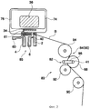
На Фиг.1 представлен вид спереди машины для упаковки и бандажирования в соответствии с вариантом настоящего изобретения.1 is a front view of a packaging and banding machine in accordance with an embodiment of the present invention.
На Фиг.2 схематически представлена контрольная часть машины по Фиг.1.Figure 2 schematically shows the control part of the machine of Figure 1.
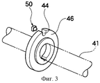
На Фиг.3 представлено перспективное изображение диска на вращательном валу, определяющего количество вращении контактного ролика.Figure 3 presents a perspective image of a disk on a rotational shaft that determines the amount of rotation of the contact roller.
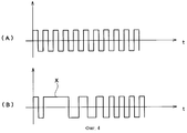
На Фиг.4А представлена диаграмма характеристики вращения контактного ролика в случае проведения первичной подачи и на Фиг.4В - диаграмма характеристики вращения контактного ролика в случае проведения вторичной подачи.Fig. 4A is a diagram of a rotation characteristic of a contact roller in the case of a primary feed, and Fig. 4B is a diagram of a rotation characteristic of a contact roller in a case of a secondary feed.
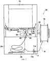
Фиг.5 - схематический вид машины для упаковки и бандажирования в соответствии с другим вариантам настоящего изобретения, а именно, машины, включающей приемную секцию вместо приемной секции для обратной протяжки.5 is a schematic view of a packaging and banding machine in accordance with other embodiments of the present invention, namely, a machine including a receiving section instead of a receiving section for backward drawing.
Описание предпочтительных вариантовDescription of Preferred Options
Ниже описан вариант настоящего изобретения со ссылкой на чертежи.An embodiment of the present invention is described below with reference to the drawings.
На Фиг.1 представлена автоматическая машина для упаковки и бандажирования в соответствии с вариантом настоящего изобретения.Figure 1 shows an automatic packaging and banding machine in accordance with an embodiment of the present invention.
В автоматической машине для упаковки и бандажирования 70 в верхней части корпуса 72 машины имеется направляющая рамка 74 для ленты, имеющая почти U-образную конфигурацию. В направляющей рамке 74 над корпусам 72 упаковочной машины имеется канавка 76, по которой протягивается лента, образующая там петлю. С другой стороны, в левосторонней части корпуса 72 упаковочной машины на Фиг.1 имеется свободно снимающаяся и надевающаяся катушка с лентой 78. Приемная секция 80 для оттянутой назад ленты выполнена разделяющей пластиной 75 в правосторонней части корпуса 72 упаковочной машины.In the automatic packaging and banding machine 70, at the top of the machine body 72 there is a
Приемная секция 80 служит для временного размещения излишка ленты В, оттянутой назад из направляющей рамки 74, когда проводится бандажирование. Соответственно, длины ленты, находящейся в приемной секции 80 для обратной протяжки, недостаточно для следующего цикла бандажирования.The receiving section 80 serves to temporarily accommodate the excess tape B pulled back from the
В такой машине 70 для упаковки и бандажирования в том случае, когда средством подачи 82, включающим пару роликов, излишек ленты, остающийся в приемной секции для обратной протяжки 80, подают к стороне направляющей рамки 74, подача идет с небольшим крутящим моментам с высокой скоростью (первичная подача ленты). С другой стороны, в том случае, когда излишка ленты нет в приемной секции для обратной протяжки 80, ленту подают с большим крутящим моментом с низкой скоростью, чтобы непосредственно протянуть ее с катушки 78 (вторичная подача ленты).In such a packaging and banding machine 70, in the case where the supply means 82, including a pair of rollers, the excess tape remaining in the receiving section for the reverse broach 80, is fed to the side of the
Более того, в машине 70 подающая часть 83 размещена между приемной секцией обратной протяжки 80 и скользящим столом 34.Moreover, in the machine 70, the
Как показано на Фиг.2, подающая часть 83 включает средство подачи ленты 82 для ее подачи к стороне направляющей рамки 74 через направляющий ролик 90, средство протяжки ленты назад 84 для протягивания ленты назад от стороны направляющей рамки 74, и средство натяжения 86 ленты для натяжения оттянутой назад ленты.As shown in FIG. 2, the feeding
Фактически, средство протяжки ленты назад 84 и средство натяжения 86 представляют собой реверсивный вращательный ролик 94 на приводящей стороне и общий контактный ролик 88 на приводной стороне соответственно. Кроме того, общий контактный ролик 88 выполняет также функцию средства подачи 82 на нормальной вращательной стороне и средства обратной протяжки 84 на реверсивной вращательной стороне (средства натяжения 86). И общий контактный ролик 88 селективно прижимом приводится в контакт с одним из роликов 92 и 94 на приводящей стороне.In fact, the belt pulling means back 84 and the tensioning means 86 are a
Общий контактный ролик 88 поддерживается звеном 96 или эксцентрическим валом. При включении в работу звена 96 или эксцентрического вала контактный ролик 88 приводится прижимом в контакт с нормальным вращательным: роликом 92 или реверсивным вращательным роликом 94.The
А именно, средство подачи ленты 82 включает в себя нормальный вращательный ролик 92 на приводящей стороне и общий контактный ролик 88 на приводной стороне. И средство обратной протяжки 84 и средство натяжения 86 ленты представляют собой реверсивный вращательный ролик 94 на приводящей стороне и общий контактный ролик 88 на приводной стороне.Namely, the tape feed means 82 includes a
Как показано на Фиг.2, когда общий контактный ролик 88 приводится прижимом в контакт с нормальным вращательным роликом 92, общий контактный ролик 88 отделяется от реверсивного вращательного ролика 94. И наоборот, когда общий контактный ролик 88 приводится прижимом в контакт с реверсивным вращательным роликом 94, общий контактный ролик 88 отделяется от нормального вращательного ролика 92.As shown in FIG. 2, when the
Когда общий контактный ролик 88 приводится прижимом в контакт с реверсивным вращательным роликом 94, лента оттягивается назад и натягивается.When the
Правый прижимной элемент 2, левый прижимной элемент 4 и средний прижимной элемент 6, которые предназначены выполнять операции прижима, сварки и резки концевой части ленты под действием кулачка, размещены прямо в горизонтальном направлении упаковочной машины ниже направляющей рамки 74. Эти три элемента вертикально перемещаются через заданные интервалы времени, что соответствует форме кулачка, расположенного на кулачковом валу в нижней части машины.The right pressing element 2, the left
Кроме того, под скользящим столом 34 в горизонтальном направлении свободно перемещается направляющий ленту элемент 60. Элемент 60 снабжен стопорам 61, на котором находится переключатель ограничения.In addition, under the sliding table 34 in the horizontal direction, the
В контрольной части 85, когда концевая часть ленты подается к направляющей рамке 74 средством подачи 82 и попадает на стопор 61 направляющего элемента 60, включается переключатель ограничения и по сигналу лента начинает оттягиваться назад и натягиваться. Прежде всего, когда конец ленты попадает на стопор 61, правый прижимной элемент 2 поднимается таким образом, что конец ленты зажимается между ним и скользящим столом 34.In the
Затем направляющий элемент 60 отодвигается назад от скользящего стола 34. Когда концевая часть ленты В находится между правым прижимным блоком 2 и скользящим столам 34, лента В оттягивается назад средствам обратной протяжки 84 к приемной секции для обратной протяжки 80.Then, the
После этого средствам натяжения ленты 86 лента вторично натягивается и левый прижимной элемент 4 поднимается, чтобы прижать ленту В к скользящему столу 34. При этом лента поддерживается в состоянии натяжения и средний прижимной элемент 6, расположенный в нижней части, поднимается, чтобы отрезать ленту резцом 40. Далее, к накладывающейся части ленты подводят нагреватель, перемещающийся в горизонтальном направлении, и поверхность ленты расплавляют. После этого средний прижимной элемент 6 вновь поднимается, чтобы прижать и зафиксировать ленту В прижимом вместе со скользящим столом 34.After that, the
В машине для упаковки и бандажирования 70 в соответствии с настоящим изобретением и нормальный вращательный ролик 92 и реверсивный вращательный ролик 94 предназначены вращаться с двумя скоростями вращения. Когда они вращаются с высокой скоростью, крутящий момент небольшой. Когда они вращаются с низкой скоростью, крутящий момент большой.In a packaging and banding machine 70 in accordance with the present invention, both the
А именно, если нормальный вращательный ролик 92 вращается с высокой скоростью, ленту можно быстро подавать к стороне направляющей рамки 74 с прохождением между нормальным вращательным роликом 92 и общим контактным роликам 88. В это время вращательный крутящий момент нормального ролика 92 небольшой. Такое условие приемлемо для ситуации, когда излишек ленты, находящейся в приемной секции для оттянутой назад ленты 80, показанной на Фиг.1, подают на сторону направляющей рамки 74 (первичная подача ленты).Namely, if the
С другой стороны, если нормальный вращательный ролик 92 вращается с низкой скоростью, ленту можно медленно подавать к стороне направляющей рамки 74. В это время вращательный крутящий момент нормального вращательного ролика 92 увеличивается. Поэтому такое условие приемлемо для ситуации, когда в приемной секции 80 нет излишка ленты и ее тянут непосредственно с катушки 78 и подают на сторону направляющей рамки 74 (вторичная подача ленты).On the other hand, if the
Далее будет описана ситуация, в которой ленту оттягивают назад и натягивают.Next, a situation will be described in which the tape is pulled back and pulled.
Если общий контактный ролик 88 приводится прижимам в контакт с реверсивным вращательным роликом 94, лента оттягивается назад и натягивается.If the
Прежде всего реверсивный вращательный ролик 94 вращается с высокой скоростью, так что лента быстро идет назад между реверсивным вращательным роликом 94 и общим контактным роликам 88. Кроме того, в это время вращательный момент реверсивного вращательного ролика 94 небольшой. Поэтому такое условие приемлемо для протяжки ленты назад после ее подачи на сторону направляющей рамки 74 (первичное натяжение ленты).First of all, the
Если реверсивный вращательный ролик 94 вращается с низкой скоростью, лента медленно оттягивается назад между реверсивным вращательным роликом 94 и общим контактным роликам 88. В это время вращательный крутящий момент реверсивного вращательного ролика 94 устанавливается большим. Поэтому такое условие приемлемо для натяжения ленты, имеющее место после протяжки ее назад (вторичное натяжение ленты). При таком условии лента натягивается сильно.If the
В такой упаковочной машине 70, если ленту подают или натягивают для осуществления различных контрольных операций, определяют количество вращении общего контактного ролика 88, скорость его вращения и другие параметры. А именно, в машине для упаковки и бандажирования 70, как показано на Фиг.3, на вращательном валу 41, поддерживающим общий контактный ролик 88, имеется интегрально выполненный с валом диск 46 с прорезью 44. С вращением вала 41 переключатель сближения 50 определяет прохождение прорези. В результате определяется направление, в котором вращается контактный ролик 88, а также количество вращении, совершаемое им.In such a packaging machine 70, if the tape is fed or pulled to carry out various control operations, the rotation amount of the
Например, если в машине 70 нужно подать ленту В из приемной секции 80 на сторону направляющей рамки 74 средствам подачи 82, ее подают с небольшим крутящим моментам с высокой скоростью нормальным вращательным роликам 92. Следовательно, скорость вращения общего контактного ролика 88 повышается.For example, if in the machine 70 it is necessary to feed the tape B from the receiving section 80 to the side of the
С другой стороны, при вторичной подаче ленты, которую проводят после завершения первичной подачи, ленту непосредственно сматывают с катушки 78 прохождением между нормальным вращательным роликом 92 и общим контактным роликам 88 и подают на сторону направляющей рамки 74. Поэтому, когда лента сматывается с катушки, нагрузка увеличивается. Следовательно, время, необходимое для одного оборота во вращении общего контактного ролика 88, продлевается.On the other hand, in the secondary feeding of the tape, which is carried out after completion of the primary feeding, the tape is directly wound from the
В настоящем варианте переключатель сближения 50 определяет, что скорость вращения общего контактного ролика 88 меняется в процессе такого перехода с первичной подачи ленты на вторичную подачу.In the present embodiment, the
Как показано на Фиг.4А, когда проводят первичную подачу ленты, напряжение переключателя сближения 50, соотнесенное с прохождением времени вращения общего контактного ролика 88, идет с постоянным импульсом при первичной подаче, поскольку прорезь 44 проходит с той же скоростью в единицу времени.As shown in FIG. 4A, when the primary feed of the tape is carried out, the voltage of the
С другой стороны, когда первичная подача ленты закончена и начинается вторичная подача, требуется больше времени на то, чтобы общий контактный ролик 88 совершил одно вращение, как показано обозначением Х на Фиг.4В. Это время постепенно сокращается и это указывает на то, что катушка 78 начинает вращаться от тяги ленты.On the other hand, when the primary feed of the tape is finished and the secondary feed starts, it takes more time for the
В этом случае ясно, что к катушке 78 подается нагрузка и общий контактный ролик 88 начинает вращаться с большим крутящим моментом с низкой скоростью.In this case, it is clear that a load is applied to the
Постепенно сопротивление катушки 78 уменьшается и вращение идет быстрее. Затем вновь возвращается состояние, в котором нагрузка не подается, как показано на Фиг.4А. Повторный переход из состояния Фиг.4В в состояние Фиг.4А указывает на то, что нагрузка катушки 78 снимается. Это говорит о том, что общий контактный ролик 88 вращается с одинаковой скоростью в единицу времени.Gradually, the resistance of the
Соответственно, в случае, когда сигнал на Фиг.4А появляется вновь, катушка 78 и лента больше не вращаются как одно целое. Следовательно, можно сделать вывод, что конец ленты отделился от катушки 78. А именно, что лента, намотанная на катушке 78, закончилась.Accordingly, in the case where the signal in FIG. 4A reappears, the
При получении такого сигнала работа средства подачи 82 временно прекращается и машина останавливается. При этом завершающий конец ленты уже не может попасть на сторону направляющей рамки 74. Он зависает и оператор может вытянуть ленту рукой и заменить использованную катушку 78 новой.Upon receipt of such a signal, the operation of the
Таким образом, в данном варианте нет необходимости использовать какой-то новый элемент, чтобы выявить завершающий конец ленты на катушке 78. Простое изменение вращения общего контактного ролика 88 указывает на момент, когда катушку следует заменить.Thus, in this embodiment, it is not necessary to use some new element to identify the final end of the tape on the
Когда лента с катушки смоталась, работа средства подачи 82 прекращается и, более того, сигнал можно вывести на дисплей, зуммер или другое подобное устройство.When the tape from the reel spools, the operation of the feed means 82 is stopped and, moreover, the signal can be displayed, a buzzer or other similar device.
Хотя был описан только один вариант настоящего изобретения, оно не ограничивается до данного варианта. Например, кроме указанного контрольного устройства, можно еще предусмотреть механизм, который не будет допускать нарушений в режиме работы.Although only one embodiment of the present invention has been described, it is not limited to this embodiment. For example, in addition to the specified control device, you can also provide a mechanism that will not allow violations in the operating mode.
Автоматическая машина для упаковки и бандажирования 70 имеет такую конструкцию, что для катушки 78 предусмотрен также тормоз, позволяющий избежать излишнего ее вращения. То есть тормоз не дает ей вращаться далее, когда нужная длина ленты уже отмотана.The automatic packaging and banding machine 70 is so designed that a brake is also provided for
Однако в некоторых случаях, когда тормоз не дает нужного эффекта, катушка 78 продолжает вращаться и вокруг катушки образуется излишек ленты.However, in some cases, when the brake does not produce the desired effect, the
При вторичной подаче недостающую длину ленты непосредственно подают вращением катушки 78. А в случае наличия такой свободно висящей ленты на катушке 78 при вторичной подаче этот излишек ленты забирается и катушка уже не вращается.In the secondary feed, the missing length of the tape is directly fed by rotating the
В этом случае затянутый во времени импульс, показанный обозначением Х на Фиг.4В, не формируется. В таком случае выводится ошибочный сигнал, что лента с катушки 78 смоталась, хотя она все еще есть на катушке 78.In this case, a time-delayed pulse, indicated by the designation X in FIG. 4B, is not generated. In this case, an erroneous signal is output that the tape from
Соответственно, чтобы этого ошибочного сигнала не было, дополнительным критерием может служить состояние наличия концевой части ленты на стороне направляющей рамки, уложенной в виде петли в рамке и достигшей установленной позиции. Чтобы предотвратить такой ошибочный сигнал, желательно установить условие, при котором будет подаваться сигнал переключателя ограничения, указывающий на состояние достижения концом ленты стопора 61 на направляющем элементе 60.Accordingly, so that this erroneous signal does not exist, an additional criterion may be the state of the presence of the end part of the tape on the side of the guide frame, laid in the form of a loop in the frame and reaching the set position. In order to prevent such an erroneous signal, it is desirable to establish a condition under which a limit switch signal will be supplied, indicating the state that the end of the tape has reached a
А конкретнее, желательно учесть следующие три условия:More specifically, it is desirable to consider the following three conditions:
(1) условие, при котором меняется вращение катушки 78;(1) the condition under which the rotation of the
(2) условие, при котором вращение катушки 78 не меняется и средство обнаружения (переключатель ограничения) определяет, что конец ленты достигает стопора 61 (переключатель включен); и(2) a condition under which the rotation of the
(3) условие, при котором вращение катушки 78 не меняется и средство обнаружения (переключатель ограничения) не определяет, что конец ленты достигает стопора 61 (переключатель выключен);(3) a condition under which the rotation of the
В случае (1) лента остается на катушке, так как описано в варианте, и идет операция бандажирования.In case (1), the tape remains on the reel, as described in the embodiment, and the banding operation is ongoing.
В случае (2) лента остается на катушке 78 и операция бандажирования ведется на основании этого сигнала.In case (2), the tape remains on the
В случае (3) лента использована и бандажирование закончено.In case (3), the tape is used and the banding is completed.
Помимо наличия изменения во вращении катушки 78 при подаче ленты, средство обнаружения определяет, достигает ли конец ленты стопора 61. Кроме того, к этим условиям добавляется сигнал, посланный средством обнаружения. Следовательно, это позволяет точнее определить, осталась ли лента на катушке 78 или катушка пуста.In addition to having a change in the rotation of the
Хотя в данном варианте в корпусе упаковочной машины 72 имеется приемная секция для оттянутой назад ленты 80, изобретение также применимо с машиной, в которой вместо приемной секции для оттянутой назад ленты 80 предусмотрена просто приемная секция.Although in this embodiment, there is a receiving section for the backward drawn tape 80 in the case of the packaging machine 72, the invention is also applicable to a machine in which, instead of the receiving section for the backward drawn tape 80, there is simply a receiving section.
На Фиг.5 показана упаковочная машина 20, имеющая такую приемную секцию 24.5 shows a
Так же как и упаковочная машина 70, машина 20 включает средство подачи ленты 82, средство обратной протяжки 84, средство натяжения 86, направляющую рамку 74 для ленты и прочие составляющие.Like the packaging machine 70, the
Более того, в упаковочной машине 20 вместо приемной секции для размещения оттянутой назад ленты предусмотрена просто приемная секция 24 в левосторонней части корпуса 23 машины. А катушка 78 расположена снаружи корпуса 23 упаковочной машины.Moreover, in the
В такой машине 20 в качестве привода для подачи ленты В от катушки 78 в приемную секцию 24 представлен ролик 11, подающий ленту к приемной секции.In such a
Подающий ролик 11 включает приводящий вал 11а, связанный с мотором, который не показан, и подающий контактный ролик 11b, который приводится в контакт с валом прижимом. В этом случае определяется вес ленты, действующий на балансную пластину 25 в приемной секции 24. В результате, если выявляется, что длина собранной ленты меньше установленной, ленту непосредственно подают с катушки 78 посредством подающего ролика 11 и ту часть, которая имеется в приемной секции 24.The
В такой упаковочной машине 20, как видно из Фиг.4, посредством определения изменения в напряжении переключателя сближения 50, соотнесенного с прохождением времени подающего контактного ролика 11b для прямого вращения катушки 78, представляется возможным определить, использована ли лента, а также определить средством обнаружения, достигает ли конец ленты стопора 61, показанного на Фиг.2.In such a
Claims (12)
Applications Claiming Priority (4)
| Application Number | Priority Date | Filing Date | Title |
|---|---|---|---|
| JP2002-286693 | 2002-09-30 | ||
| JP2002286693 | 2002-09-30 | ||
| JP2003310525A JP2004142830A (en) | 2002-09-30 | 2003-09-02 | Band winding packing machine |
| JP2003-310525 | 2003-09-02 |
Publications (2)
| Publication Number | Publication Date |
|---|---|
| RU2003129021A RU2003129021A (en) | 2005-03-27 |
| RU2254273C1 true RU2254273C1 (en) | 2005-06-20 |
Family
ID=31980654
Family Applications (1)
| Application Number | Title | Priority Date | Filing Date |
|---|---|---|---|
| RU2003129021/12A RU2254273C1 (en) | 2002-09-30 | 2003-09-30 | Packaging and banding machine |
Country Status (14)
| Country | Link |
|---|---|
| US (1) | US6928787B2 (en) |
| EP (1) | EP1403184B1 (en) |
| JP (1) | JP2004142830A (en) |
| KR (1) | KR100543163B1 (en) |
| CN (1) | CN1248915C (en) |
| AT (1) | ATE349379T1 (en) |
| AU (1) | AU2003248444B2 (en) |
| BR (1) | BR0304988A (en) |
| CA (1) | CA2443500C (en) |
| DE (1) | DE60310659T2 (en) |
| ES (1) | ES2275069T3 (en) |
| PL (1) | PL362536A1 (en) |
| RU (1) | RU2254273C1 (en) |
| TW (1) | TWI230673B (en) |
Families Citing this family (19)
| Publication number | Priority date | Publication date | Assignee | Title |
|---|---|---|---|---|
| CH696398A5 (en) * | 2003-11-21 | 2007-05-31 | Automatic Taping Systems | Method for banding stacked, soft and / or sensitive packaged goods |
| US9241497B2 (en) | 2005-06-30 | 2016-01-26 | The United States Of America, As Represented By The Secretary Of Agriculture | Method and apparatus for treatment of food products |
| JP4858488B2 (en) * | 2008-05-19 | 2012-01-18 | マックス株式会社 | Rebar binding machine |
| JP5896592B2 (en) * | 2010-03-19 | 2016-03-30 | ストラパック株式会社 | Packing equipment |
| DE202010007012U1 (en) * | 2010-05-20 | 2010-09-16 | Krones Ag | Impact device with a rod-shaped impact element |
| SE1000661A1 (en) * | 2010-06-20 | 2011-12-21 | Mowi Teknik Ab | Method and apparatus for supplying wire to a binding machine |
| EP2619095A1 (en) * | 2010-09-22 | 2013-07-31 | Bobst Mex Sa | Strapping device for packaging machine |
| CN102530291B (en) * | 2011-12-22 | 2013-07-10 | 杭州永创智能设备股份有限公司 | Novel packing machine |
| DE102014225880A1 (en) * | 2014-12-15 | 2016-06-16 | Krones Aktiengesellschaft | Strapping head and method of handling a strapping band |
| ES2553475B1 (en) * | 2015-07-31 | 2016-07-11 | Neutroleader, S.L.U | Modules for sealing machines |
| NL2015589B1 (en) * | 2015-10-08 | 2017-05-02 | Bandall Productie B V | Device for banding products. |
| NL2015588B1 (en) * | 2015-10-08 | 2017-05-02 | Bandall Productie B V | Device for banding products. |
| CN107010276A (en) * | 2016-01-27 | 2017-08-04 | 广州国诺自动化设备有限公司 | A kind of revolving ring type automatic winding cartoning sealing machine |
| CN106005541A (en) * | 2016-07-19 | 2016-10-12 | 昆山沃优自动化设备科技有限公司 | Negative-pressure walk belt binding device |
| CN106137560A (en) * | 2016-07-29 | 2016-11-23 | 吴江富凯医用卫生用品有限公司 | Wrapping assembly deposited by the bandage of a kind of automatic rotation |
| US11021282B2 (en) | 2017-07-19 | 2021-06-01 | Signode Industrial Group Llc | Strapping device configured to carry out a strap-attachment check cycle |
| KR102071417B1 (en) * | 2019-05-22 | 2020-01-30 | 강석휘 | Banding apparatus |
| KR102336302B1 (en) * | 2019-10-14 | 2021-12-08 | (주)바인텍 | Binding machine with switching motion mode |
| CN113753345A (en) * | 2021-09-15 | 2021-12-07 | 河钢股份有限公司承德分公司 | Online prediction management system for packing machine line tower and use method |
Family Cites Families (33)
| Publication number | Priority date | Publication date | Assignee | Title |
|---|---|---|---|---|
| US3137426A (en) * | 1960-11-24 | 1964-06-16 | Forsch Anstalt Fuer Mechanik | Reserve container |
| JPS5144472B2 (en) * | 1974-02-18 | 1976-11-29 | ||
| JPS53102199A (en) * | 1977-02-17 | 1978-09-06 | Nichiro Kogyo Kk | Method for packing by way of thermoplastic band |
| US4120239A (en) * | 1977-03-10 | 1978-10-17 | Ovalstrapping, Inc. | Strapping machine |
| GB2019040A (en) * | 1978-01-28 | 1979-10-24 | Power Ltd F A | Feeding Filamentary Material |
| JPS55164103U (en) * | 1979-05-14 | 1980-11-26 | ||
| DE3300039A1 (en) * | 1982-01-08 | 1983-07-21 | Shoko Kiko Co., Ltd., Shijo nawate, Osaka | METHOD FOR REGULATING THE TENSION OF A RETURNING TAPE IN A RETURNING MACHINE |
| CH668402A5 (en) * | 1985-03-15 | 1988-12-30 | Konrad Feinmechanik Ag A | METHOD AND MACHINE FOR STRAPPING A PACKAGE WITH A STRAP. |
| JPH0531043Y2 (en) * | 1986-10-14 | 1993-08-10 | ||
| CA1320427C (en) * | 1987-06-18 | 1993-07-20 | Yasunori Sakaki | Method and apparatus for feeding and tightening a band in strapping machine |
| JPH0759410B2 (en) * | 1988-02-08 | 1995-06-28 | ニチロ工業株式会社 | Automatic band loading device for arch type automatic packing machine |
| DE3825668C1 (en) * | 1988-07-28 | 1990-02-15 | Signode Bernpak Gmbh, 5630 Remscheid, De | |
| JPH03111220A (en) * | 1989-09-18 | 1991-05-13 | Meiwa Kk | Band packing machine |
| US5112004A (en) * | 1990-11-07 | 1992-05-12 | Illinois Tool Works Inc. | Strap dispensing and accumulating apparatus and combination of same with strapping machine |
| JP2857280B2 (en) * | 1992-06-10 | 1999-02-17 | ストラパック株式会社 | Band supply / tightening method and device for packing machine |
| JP2857281B2 (en) * | 1992-07-10 | 1999-02-17 | ストラパック株式会社 | Band loading device in packing machine |
| US5333438A (en) * | 1992-11-06 | 1994-08-02 | Signode Corporation | Dual coil power strapping machine |
| US5287802A (en) | 1992-12-14 | 1994-02-22 | Signode Corporation | Strap severing and ejecting mechanism for strapping machine |
| DE4313420A1 (en) * | 1993-04-23 | 1994-10-27 | Krupp Ag Hoesch Krupp | Strapping device |
| JPH07187119A (en) * | 1993-12-28 | 1995-07-25 | Kioritz Corp | Packing machine |
| TW291470B (en) * | 1995-02-14 | 1996-11-21 | Nichiro Kogyo Kk | |
| US5809873A (en) | 1996-11-18 | 1998-09-22 | Ovalstrapping, Inc. | Strapping machine having primary and secondary tensioning units and a control system therefor |
| JPH11255206A (en) * | 1998-03-10 | 1999-09-21 | Naigai Kk | Guide path structure for moving band in packing machine |
| JP3697365B2 (en) * | 1999-04-02 | 2005-09-21 | ストラパック株式会社 | Band end discharge method for packing machine |
| IT1313685B1 (en) * | 1999-11-25 | 2002-09-09 | Macpro S A S Di Alberto Galli | STRAPPING HEAD FOR PACKAGING MACHINE. |
| JP2002029504A (en) * | 2000-07-19 | 2002-01-29 | Strapack Corp | Band feeding length adjustment device in packing machine |
| JP2002067089A (en) | 2000-08-23 | 2002-03-05 | Polyplastics Co | Method for forming hollow molding of synthetic resin, molding and mold therefor |
| JP4493831B2 (en) * | 2000-11-16 | 2010-06-30 | ストラパック株式会社 | Control device for banding packing machine |
| EP1249397B1 (en) * | 2001-04-09 | 2005-01-19 | Nichiro Kogyo Co., Ltd. | Arch type strapping machine |
| US6629398B2 (en) | 2001-07-12 | 2003-10-07 | Illinois Tool Works, Inc. | Strapping machine with improved refeed |
| JP3985244B2 (en) * | 2001-11-09 | 2007-10-03 | 株式会社東京機械製作所 | Band bundling device and bundling transport system provided with this device |
| JP4147043B2 (en) | 2002-03-12 | 2008-09-10 | ストラパック株式会社 | Banding packing machine |
| DE20212157U1 (en) * | 2002-08-07 | 2002-11-14 | Tekpak Corp | Tape storage controller |
-
2003
- 2003-09-02 JP JP2003310525A patent/JP2004142830A/en active Pending
- 2003-09-29 KR KR1020030067469A patent/KR100543163B1/en not_active IP Right Cessation
- 2003-09-29 AU AU2003248444A patent/AU2003248444B2/en not_active Ceased
- 2003-09-29 TW TW092126901A patent/TWI230673B/en not_active IP Right Cessation
- 2003-09-30 CA CA002443500A patent/CA2443500C/en not_active Expired - Fee Related
- 2003-09-30 AT AT03256150T patent/ATE349379T1/en not_active IP Right Cessation
- 2003-09-30 PL PL03362536A patent/PL362536A1/en unknown
- 2003-09-30 BR BR0304988-4A patent/BR0304988A/en not_active IP Right Cessation
- 2003-09-30 DE DE60310659T patent/DE60310659T2/en not_active Expired - Lifetime
- 2003-09-30 US US10/675,519 patent/US6928787B2/en not_active Expired - Fee Related
- 2003-09-30 RU RU2003129021/12A patent/RU2254273C1/en not_active IP Right Cessation
- 2003-09-30 ES ES03256150T patent/ES2275069T3/en not_active Expired - Lifetime
- 2003-09-30 EP EP03256150A patent/EP1403184B1/en not_active Expired - Lifetime
- 2003-09-30 CN CNB031434843A patent/CN1248915C/en not_active Expired - Fee Related
Also Published As
| Publication number | Publication date |
|---|---|
| DE60310659T2 (en) | 2007-08-09 |
| PL362536A1 (en) | 2004-04-05 |
| EP1403184A1 (en) | 2004-03-31 |
| AU2003248444A1 (en) | 2004-04-22 |
| JP2004142830A (en) | 2004-05-20 |
| CA2443500C (en) | 2007-03-27 |
| RU2003129021A (en) | 2005-03-27 |
| CN1248915C (en) | 2006-04-05 |
| CA2443500A1 (en) | 2004-03-30 |
| TWI230673B (en) | 2005-04-11 |
| EP1403184B1 (en) | 2006-12-27 |
| TW200415075A (en) | 2004-08-16 |
| AU2003248444B2 (en) | 2005-09-01 |
| CN1496926A (en) | 2004-05-19 |
| KR100543163B1 (en) | 2006-01-20 |
| US20040060267A1 (en) | 2004-04-01 |
| BR0304988A (en) | 2004-04-27 |
| KR20040028591A (en) | 2004-04-03 |
| ATE349379T1 (en) | 2007-01-15 |
| ES2275069T3 (en) | 2007-06-01 |
| DE60310659D1 (en) | 2007-02-08 |
| US6928787B2 (en) | 2005-08-16 |
Similar Documents
| Publication | Publication Date | Title |
|---|---|---|
| RU2254273C1 (en) | Packaging and banding machine | |
| TWI222947B (en) | Automatic banding packing machine | |
| KR101708148B1 (en) | Brake system of wire reel in reinforcing bar binding machine | |
| US4938009A (en) | Automatic package strapping machine | |
| LT5485B (en) | Reinforcing bar binder, wire reel and method for indentifying wire reel | |
| US3946921A (en) | Apparatus for feeding packaging strap | |
| JP2004142813A (en) | Reinforcement bundler | |
| JP2004142830A5 (en) | ||
| RU2257312C2 (en) | Method for repeated advancing strap in packing-and-strapping machine and packing-and-strapping machine including the mechanism | |
| JP5045549B2 (en) | Brake device for wire reel in rebar binding machine and brake processing method thereof | |
| US6981353B2 (en) | Strapping machine with strap feeding and tensioning system with automatic refeed | |
| JP4016799B2 (en) | Rebar binding machine | |
| TWI581875B (en) | Reinforcing bar binding machine | |
| JP4994696B2 (en) | Automatic tape hooking machine | |
| CN214524571U (en) | Power type full-automatic bundling machine | |
| JP2000281011A (en) | Band changeover device for band binding machine | |
| JP5582131B2 (en) | Brake device for wire reel in rebar binding machine and brake processing method thereof | |
| JP2932259B2 (en) | Tape marker insertion device | |
| JPH05193607A (en) | Band slack removing method for band reel by pool feed unit of packaging machine | |
| JPH08119214A (en) | Automatic packing machine | |
| JP2007308179A (en) | Baler | |
| JPH07310242A (en) | Method for shutdown in spinning machine and shutdown control unit | |
| JP2001199408A (en) | Automatic discharging apparatus for tip portion in automatic packing machine | |
| JPH06525B2 (en) | Tape tightening force adjusting device for packing machine | |
| JPS6350261B2 (en) |
Legal Events
| Date | Code | Title | Description |
|---|---|---|---|
| MM4A | The patent is invalid due to non-payment of fees |
Effective date: 20101001 |