RU2253623C1 - Device for purification of 0il-polluted sewage - Google Patents
Device for purification of 0il-polluted sewage Download PDFInfo
- Publication number
- RU2253623C1 RU2253623C1 RU2003132813/15A RU2003132813A RU2253623C1 RU 2253623 C1 RU2253623 C1 RU 2253623C1 RU 2003132813/15 A RU2003132813/15 A RU 2003132813/15A RU 2003132813 A RU2003132813 A RU 2003132813A RU 2253623 C1 RU2253623 C1 RU 2253623C1
- Authority
- RU
- Russia
- Prior art keywords
- sump
- collector
- oil
- tubular
- water
- Prior art date
Links
Images
Landscapes
- Production Of Liquid Hydrocarbon Mixture For Refining Petroleum (AREA)
Abstract
Description
Изобретение относится к технике очистки нефтесодержащих сточных вод нефтепромыслов и может быть использовано в других отраслях промышленности, сельского хозяйства и т.д., сточные воды которых содержат нефть и нефтепродукты.The invention relates to techniques for cleaning oily wastewater from oil fields and can be used in other industries, agriculture, etc., the wastewater of which contains oil and oil products.
Известно устройство для очистки нефтесодержащих сточных вод по а.с. СССР № 1699935, C 02 F 1/00, В 01 D 17/038, опубл. 23.12.91, Бюл. №47, включающее отстойник с нефтесборником, патрубок для ввода эмульсии, выполненный с соотношением диаметра к длине, равным 1:10 - 1:50, гидроциклонную камеру с тангенциальным вводом, которая снабжена диспергатором в виде сопла, патрубки для отвода очищенной воды, уловленной нефти и осадка.A device for purifying oily wastewater according to.with. USSR No. 1699935, C 02
Недостатками данного устройства является низкая эффективность очистки нефтесодержащих сточных вод вследствие неполного использования энергии закрученного потока в патрубке, соединяющем отстойник и трубу с диспергатором. Это объясняется тем, что практически вся энергия закрученного потока затрачивается на разделение эмульсии на нефть и воду, а не на коалесценцию капель нефти при движении их по патрубку.The disadvantages of this device is the low efficiency of treatment of oily wastewater due to the incomplete use of the energy of the swirling flow in the pipe connecting the sump and the pipe with a dispersant. This is due to the fact that almost all the energy of the swirling flow is spent on the separation of the emulsion into oil and water, and not on the coalescence of oil droplets when moving along the pipe.
Кроме того, для нормальной работы горизонтального отстойника известного устройства необходимо своевременное и полное удаление осадка из него. В известном устройстве из горизонтального отстойника осадок удаляется под давлением не полностью, так как усилия, размывающие отложившийся осадок, действуют только в зоне образования струй, а за их пределами масса осадка остается неподвижной даже при больших уклонах дна.In addition, for the normal operation of the horizontal sump of the known device, timely and complete removal of sediment from it is necessary. In the known device, the sediment is not completely removed from the horizontal settler under pressure, since the forces eroding the deposited sediment act only in the formation zone of the jets, and beyond them the mass of the sediment remains motionless even with large slopes of the bottom.
Все это способствует накоплению осадка, разложению накопившегося нестабильного осадка с выделением газов в отстойнике, что ухудшает гидродинамические условия отстаивания, и снижает эффект очистки нефтесодержащих сточных вод.All this contributes to the accumulation of sludge, decomposition of the accumulated unstable sludge with the release of gases in the sump, which worsens the hydrodynamic conditions of sedimentation, and reduces the effect of purification of oily wastewater.
Известно устройство для очистки нефтесодержащих сточных вод по а.с. СССР № 837925, C 02 F 1/00, опубл. 15.06.81, Бюл. № 22, включающее отстойник с нефтесборником, патрубок ввода эмульсии, патрубки вывода соответственно очищенной воды, уловленной нефти и шлама. К патрубку ввода эмульсии тангенциально присоединена труба, в которой установлен диспергатор-сопло.A device for purifying oily wastewater according to.with. USSR No. 837925, C 02
Недостатком данного устройства является низкая эффективность очистки нефтесодержащих сточных вод вследствие недостаточного использования энергии закрученного потока в патрубке, подающем эмульсию в отстойник, а также вследствие недостаточно полного удаления осадка со дна отстойника.The disadvantage of this device is the low efficiency of purification of oily wastewater due to insufficient use of the swirl flow energy in the pipe supplying the emulsion to the sump, as well as due to insufficient removal of sludge from the bottom of the sump.
Прототипом изобретения является устройство для очистки нефтесодержащих сточных вод по патенту РФ на изобретение № 2189360, C 02 F 1/40, опубл. 20.09.2002, Бюл. №26, включающее трубопровод для подачи исходной воды, напорный гидроциклон, цилиндрические камеры верхнего слива и нижнего слива гидроциклона. В верхней части рабочей зоны отстойника расположены распределительные устройства для воды из верхнего слива и нижнего слива гидроциклона, в которые поступает вода из цилиндрических камер. Отстойник имеет разделительные перегородки, делящие отстойник на рабочую и буферную зоны. В верхней части отстойника расположены нефтесборники с патрубками для отвода нефти. Устройство для отвода очищенной воды с отбойником расположено в буферной зоне отстойника. В нижней части отстойника установлены патрубки для отвода осадка. В верхней части отстойника образуется слой нефти.The prototype of the invention is a device for the purification of oily wastewater according to the patent of the Russian Federation for invention No. 2189360, C 02
Недостатком данного устройства является низкая эффективность очистки нефтесодержащих сточных вод (НСВ) вследствие несовершенства, неполного удаления осадка со дна отстойника, т.к. усилия, размывающие отложившийся осадок, действуют только в зоне образования струи, а за их пределами масса осадка остается неподвижной, происходит дальнейшее накопление осадка с одновременным возможным разложением накопившегося осадка с выделением газов. Все это ухудшает гидродинамические условия очистки отстаиванием и, как следствие, снижает эффект очистки сточной воды.The disadvantage of this device is the low efficiency of purification of oily wastewater (LWW) due to imperfections, incomplete removal of sludge from the bottom of the sump, because the forces that erode the deposited sediment act only in the zone of formation of the jet, and beyond them the mass of the sediment remains motionless, a further accumulation of sediment occurs with the simultaneous possible decomposition of the accumulated sediment with the release of gases. All this worsens the hydrodynamic conditions of treatment by settling and, as a result, reduces the effect of wastewater treatment.
Недостатком известного устройства является также то, что сбор и отвод очищенной воды из буферной зоны осуществляется точечно через патрубок с отбойником, что не позволяет осуществить достаточно равномерный сбор и отвод очищенной воды по живому сечению отстойника, и что приводит к образованию застойных зон и уменьшению коэффициента объемного использования, буферной зоны, а вследствие этого снижается эффект очистки воды. Низкий эффект очистки в известном устройстве обусловлен следующими его недостатками: несовершенство конструкции сборных устройств для удаления осадка и очищенной воды, накопление осадка на дне отстойника, значительное снижение турбулентности в транспортной зоне, наличие третьего компонента - механических примесей, высокой концентрации на межфазной поверхности, а также наличие высокой полидисперсной мелкодисперсной эмульгированной нефти и неустойчивой гидродинамической обстановки в транспортной зоне. При этом конструкции распределительных и сборных устройств в основном определяют гидродинамический режим процесса очистки как в зоне турбулентного перемешивания, так и в транспортной зоне, а также в буферной зоне.A disadvantage of the known device is that the collection and removal of purified water from the buffer zone is carried out pointwise through a pipe with a chipper, which does not allow for a fairly uniform collection and removal of purified water over the living section of the sump, and which leads to the formation of stagnant zones and a decrease in volumetric coefficient use, buffer zone, and as a result, the effect of water purification is reduced. The low cleaning effect in the known device is due to the following disadvantages: imperfect design of prefabricated devices for removing sludge and purified water, accumulation of sludge at the bottom of the sump, a significant decrease in turbulence in the transport zone, the presence of the third component - mechanical impurities, high concentration on the interface, and the presence of a high polydisperse finely dispersed emulsified oil and an unstable hydrodynamic situation in the transport zone. Moreover, the designs of distribution and prefabricated devices mainly determine the hydrodynamic regime of the cleaning process both in the turbulent mixing zone, and in the transport zone, as well as in the buffer zone.
Недостатком известного устройства также является то, что на границе раздела фаз “нефть-вода” возможно образование промежуточного слоя из примесей, содержащихся в исходной воде. При накоплении примесей в слое и уплотнении этого слоя содержимое этого слоя потоком воды транспортной зоны попадает в осветляемую воду и снижает эффект очистки.A disadvantage of the known device is also that at the oil-water interface, an intermediate layer may be formed from impurities contained in the source water. With the accumulation of impurities in the layer and compaction of this layer, the contents of this layer with the flow of water from the transport zone fall into the clarified water and reduce the cleaning effect.
Изобретение направлено на повышение эффекта очистки нефтесодержащей сточной воды за счет совершенствования конструкции и размещения распределительных и сборных устройств гидроциклонов и отстойника, а также за счет размещения и использования гидродинамических коалесцирующих насадок-фильтров с крупнозернистой гидрофобной загрузкой.The invention is aimed at increasing the effect of purification of oily wastewater by improving the design and placement of distribution and prefabricated devices for hydrocyclones and a sump, as well as by placing and using hydrodynamic coalescing filter nozzles with a coarse-grained hydrophobic load.
Решение задачи достигается тем, что в предлагаемом устройстве, включающем гидроциклон с патрубками подвода исходной воды, отвода верхнего и нижнего сливов, цилиндрические камеры на выходе верхнего и нижнего сливов гидроциклона, отстойник, снабженный перегородками: не доходящей до верхней его части и не доходящей до нижней его части, делящими отстойник на рабочую и буферную секции; распределительные устройства для воды из верхнего и нижнего сливов гидроциклона, расположенные в верхней части рабочей секции отстойника, патрубки для отвода нефти, очищенной воды и осадка, согласно изобретению оно снабжено не менее чем двумя гидроциклонами, объединенными напорным трубчатым кольцом распределения исходной воды, цилиндрические камеры гидроциклонов снабжены напорными кольцами сбора верхнего и нижнего сливов, установленными на выходе соответствующих камер, нижняя часть отстойника снабжена по центру трубчатым дырчатым коллектором для сбора и удаления осадка с отверстиями, расположенными снизу в шахматном порядке под углом не более 30° к его вертикальной оси, а выше коллектора с двух его сторон симметрично расположены трубчатые телескопические равноплечие коллекторы, снабженные соплами для смыва осадка, при этом сопла установлены перпендикулярно к телескопическим коллекторам и направлены в сторону трубчатого дырчатого коллектора для сбора и удаления осадка, и при этом ось каждого сопла совпадает с перпендикулярной линией, соединяющей центр окружности сопла на месте его установки к телескопическому коллектору с точкой пересечения этой линии с осью трубчатого дырчатого коллектора для сбора и удаления осадка; пространство между вертикальными перегородками снабжено гидродинамической крупнозернистой гидрофобной фильтрующей загрузкой, при этом диаметр зерен загрузки 15-20 мм, высота слоя загрузки 0,8-1 м, скорость фильтрации 0,5-100 м/ч; рабочая секция отстойника снабжена трубчатыми дырчатыми коллекторами-распределителями нижнего и верхнего сливов гидроциклона, размещенными соответственно друг над другом, при этом распределитель верхнего слива верхней своей плоскостью расположен на уровне границ раздела фаз “вода-высококонцентрированная эмульсия”, а распределитель нижнего слива верхней своей плоскостью расположен на границе раздела фаз “нефть-высококонцентрированная эмульсия”, при этом отверстия распределителей расположены в верхней части ответвлений распределителей в шахматном порядке и под углом 45° к вертикальной оси ответвления; отстойник снабжен также трубчатым дугообразным равноплечим дырчатым коллектором и дугообразным отбойником для сбора и удаления очищенной воды, расположенными в торце буферной секции по всей ширине и выше горизонтальной оси отстойника на расстоянии не менее 0,3 его диаметра и выполненными с радиусами кривизны, равными радиусу кривизны сферического торца отстойника, при этом отверстия расположены в верхней части указанного коллектора в шахматном порядке под углом не более 30° к вертикальной его оси, а дугообразный отбойник верхним своим концом наглухо прикреплен к торцу отстойника над коллектором на расстоянии 0,5 диаметра коллектора, а другой конец отбойника расположен ниже горизонтальной оси отстойника на 0,12-0,14 его диаметра.The solution to the problem is achieved by the fact that in the proposed device, which includes a hydrocyclone with nozzles for supplying source water, drainage of the upper and lower drains, cylindrical chambers at the outlet of the upper and lower drains of the hydrocyclone, a sump equipped with partitions: not reaching the upper part and not reaching the lower its parts dividing the sump into the working and buffer sections; distributors for water from the upper and lower discharge of the hydrocyclone located in the upper part of the working section of the sump, pipes for draining oil, purified water and sludge, according to the invention it is equipped with at least two hydrocyclones united by a pressure pipe ring distribution of the source water, cylindrical chambers of hydrocyclones equipped with pressure rings for collecting the upper and lower drains installed at the outlet of the respective chambers, the lower part of the sump is provided with a tubular hole in the center collector for collecting and removing sludge with holes staggered below at an angle of not more than 30 ° to its vertical axis, and tubular telescopic equal arms are symmetrically located on both sides of the collector, equipped with nozzles for washing the sediment, while the nozzles are installed perpendicular to the telescopic collectors and directed towards the tubular hole collector to collect and remove sediment, and the axis of each nozzle coincides with the perpendicular line connecting the center of the circle a nozzle at the installation site to a telescopic collector with the point of intersection of this line with the axis of the perforated tubular collector for collecting and removing the precipitate; the space between the vertical partitions is equipped with a hydrodynamic coarse-grained hydrophobic filter load, with a grain diameter of the load of 15-20 mm, a height of the load layer of 0.8-1 m, a filtration rate of 0.5-100 m / h; the working section of the sump is equipped with tubular hole collectors-distributors of the lower and upper discharges of a hydrocyclone located respectively one above the other, while the distributor of the upper discharge with its upper plane is located at the level of the “water-highly concentrated emulsion” interface, and the distributor of the lower discharge is located with its upper plane at the oil-highly concentrated emulsion phase boundary, with the holes of the distributors located in the upper part of the distribution branches eliteley staggered at an angle of 45 ° to the vertical axis of the branch; the sump is also equipped with a tubular arched equal-shouldered hole collector and an arched chipper for collecting and removing purified water located at the end of the buffer section along the entire width and above the horizontal axis of the sump at a distance of at least 0.3 of its diameter and made with radii of curvature equal to the radius of curvature of the spherical the end of the sump, while the holes are located in the upper part of the specified collector in a checkerboard pattern at an angle of not more than 30 ° to its vertical axis, and the arcuate chipper ontsom tightly attached to the end of the settler over the collector manifold at a distance of 0.5 diameter and the other end of the baffle plate is located below the horizontal axis to the settler 0,12-0,14 its diameter.
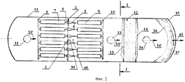
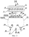
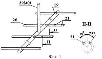
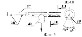
На фиг.1 изображен разрез принципиальной схемы устройства для очистки нефтесодержащей сточной воды, на фиг.2 - вид сверху, на фиг.3 - разрез по I-I, на фиг.4 - общий вид распределителей исходной воды, на фиг.5 - общий вид системы смыва осадка, на фиг.6 - общий вид сборной дырчатой системы для удаления осадка, на фиг.7 - общий вид системы для сбора и удаления очищенной воды.In Fig.1 shows a section of a schematic diagram of a device for purifying oily wastewater, Fig.2 is a top view, Fig.3 is a section along II, Fig.4 is a General view of the source water dispensers, Fig.5 is a General view sludge washing system, Fig.6 is a General view of a prefabricated hole system for removing sludge, Fig.7 is a General view of a system for collecting and removing purified water.
Устройство состоит из трубопровода 1 подачи исходной нефтесодержащей сточной воды (НСВ), напорного трубчатого распределительного кольца 2, связанного с гидроциклонами 3, например шестью гидроциклонами или как минимум двумя гидроциклонами, патрубками подачи 4 исходной НСВ, отвода верхнего слива 5 и отвода нижнего слива 6. Напорное кольцо 2 служит для равномерного распределения воды по гидроциклонам 3. Гидроциклоны 3 снабжены цилиндрическими камерами верхнего слива 7 и нижнего слива 8. Камеры верхнего слива 7 снабжены напорным трубчатым сборным кольцом 9. Камеры нижнего слива 8 снабжены напорным трубчатым сборного кольцом 10 (фиг.1, 2). Напорное кольцо 9 и 10 служат для равномерного сбора воды из камер 7 и 9 соответственно.The device consists of a
Отстойник 11 снабжен гидродинамической коалесцирующей насадкой 12 с гранулированной крупнозернистой фильтрующей загрузкой из гидрофобного (например, полиэтиленового) материала. Коалесцирующая насадка 12 расположена между перегородкой 13, не доходящей до нижней части отстойника 11 и перегородкой 14, не доходящей до верхней части отстойника 11. Перегородки 13 и 14 делят отстойник 11 на две секции: 15 - рабочая секция и 16 - буферная секция. Гидродинамическая насадка (фильтр) 12 служит для интенсификации наиболее полной коалесценции (укрупнения) капель нефти, что способствует интенсификации и повышению глубины последующей очистки НСВ отстаиванием. Секция 16 служит для дополнительной очистки воды отстаиванием. В верхней части рабочей секции 15 отстойника 11 расположены: перфорированный трубчатый распределитель 17 для НСВ, поступающей из цилиндрических камер верхнего слива 7 гидроциклонов 3 и перфорированный трубчатый распределитель 18 для НСВ из нижнего слива 8 гидроциклонов 3. Распределители 17 и 18 выполнены в виде (фиг.1, 4) коллекторов 19 с ответвлениями 20, в верхней части которых в шахматном порядке под углом 45° к вертикальной оси ответвления (фиг.4) расположены выходные отверстия 21 с направлением вытекающего потока НСВ вверх.The
Распределитель 17 верхнего слива расположен (фиг.1, 3) под распределителем 18 нижнего слива, при этом распределитель 17 верхней своей плоскостью размещен на уровне границы фаз 22-23 “вода 22 - высококонцентрированная эмульсия 23” (т.е. или на границе зоны турбулентного перемешивания 24 и транспортной зоны 25), а распределитель 18 верхней своей плоскостью размещен на уровне границы фаз (26-23) “нефть 26 - высококонцентрированная эмульсия 23” (т.е. на границе зоны накопления уловленной нефти 26 и зоны турбулентного перемешивания 24) (фиг.1).The
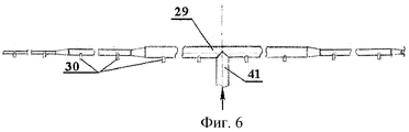
В нижней части посередине отстойника 11 (фиг.1, 3) размещена трубчатая сборная дырчатая система для удаления осадка, которая представляет собой (фиг.5) напорный трубопровод-коллектор 27 с отверстиями 28, расположенными снизу коллектора в шахматном порядке и под углом не более 30° к вертикальной оси коллектора 27. Выше и с двух сторон коллектора 27 размещена система смыва (фиг.1, 3) для смыва накопившегося осадка со дна отстойника 11, которая выполнена (фиг.6) в виде симметрично расположенных напорных равноплечных телескопических трубопроводов-коллекторов 29 с соплами 30, направленными в сторону сборной дырчатой системы - трубопровода коллектора с отверстиями 27. Сопла 30 установлены перпендикулярно к телескопическим коллекторам 29 и направлены в сторону трубчатого дырчатого коллектора 27, при этом ось каждого сопла совпадает с перпендикулярной линией, соединяющей центр окружности сопла 30 на месте его установки к телескопическому коллектору 29 с точкой пересечения этой линии с осью трубчатого дырчатого коллектора 27.In the lower part in the middle of the sump 11 (Figs. 1, 3) there is a tubular prefabricated hole system for removing sludge, which is (Fig. 5) a
В нижней части буферной секции 16 отстойника 11 также размещены трубчатая сборная дырчатая система 31 и система смыва с соплами 32, аналогичными по конструкции выше описанным.In the lower part of the buffer section 16 of the
В верхней части отстойника 11 расположены нефтесборники 33 и 34 с патрубками 33’ и 34’ для отвода уловленной нефти.In the upper part of the
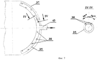
Для сбора и удаления очищенной воды буферная секция 16 отстойника 11 снабжена дугообразным равноплечим трубчатым дырчатым коллектором 35 и дугообразным отбойником 36 (фиг.1, 2, 7). Коллектор 35 расположен в торцевой части буферной зоны выше горизонтальной оси отстойника 11 на расстоянии от торца не менее 0,3 его диаметра. Коллектор 35 и отбойник 36 (фиг.2) имеют радиус кривизны, совпадающий с радиусом сферического торца 37 отстойника 11. Коллектор 35 выполнен (фиг.7) дугообразным с отверстиями 38, расположенными сверху в шахматном порядке под углом не более 30° к вертикальной оси коллектора. Дугообразный отбойник 36 верхним своим концом наглухо прикреплен к торцу 37 отстойника 11 над коллектором 35 на расстоянии 0,5 диаметра коллектора, а другой конец отбойника 36 расположен ниже горизонтальной оси отстойника 11 на 0,12-0,14 диаметра отстойника.To collect and remove purified water, the buffer section 16 of the
Коллектор 35 и отбойник 36 обеспечивают равномерный сбор очищенной воды по живому сечению буферной секции 16 отстойника 11, при этом отбойник 36 также способствует гашению придонных потоков, фиксации в буферной секции 16 объемов дополнительного отстаивания и накопления осадка.The
Устройство работает следующим образом. Сточная вода (НСВ), содержащая плавающую и эмульгированную нефть и механические примеси по трубопроводу 1 под напором подается через напорное трубчатое распределительное кольцо 2, в гидроциклоны 3 (например, шесть гидроциклонов, но как минимум два гидроциклона). В гидроциклонах 3 осуществляется гидродинамическая обработка НСВ в поле центробежных массовых, а также поверхностных сил, в результате чего разрушаются бронирующие оболочки на частицах (каплях, глобулах) нефти и агрегаты из механических примесей, происходит укрупнение капель нефти, увеличивается монодисперсность внутренней нефтяной фазы эмульсии, а также происходит разделение НСВ на два потока эмульсии: поток из верхних сливов 5 гидроциклонов 3 поступает в цилиндрические камеры 7, а поток из нижних сливов 6 в цилиндрические камеры 8. Потоки эмульсии поступают в цилиндрические камеры 7 и 8 в виде закрученных струй, при этом увеличивается время гидродинамической обработки эмульсии в закрученном поле массовых, а также поверхностных сил, энергия которых используется для наиболее полной реализации всех стадий механизма разрушения нефтяной эмульсии (деформация и разрушение бронирующих оболочек на глобулах нефти; сближение, столкновение капель; слияние и укрупнение (коалесценция) капель; концентрация, осаждение капель; выделение дисперсной фазы в виде сплошной фазы - расслоение, разделение эмульсии на нефть и воду) и, как следствие, повышается эффективность очистки НСВ. Далее из цилиндрических камер 7 поток эмульсии поступает в напорное трубчатое сборное кольцо 9, а далее по трубопроводу 39 в распределитель 17, и из него в виде равномерно распределенного потока в слой высококонцентрированной по нефти эмульсии 23 (т.е. в зону турбулентного перемешивания 24), где происходит интенсивная коалесценция капель нефти, переход укрупнившихся капель нефти в слой уловленной нефти 26, контактная очистка НСВ от нефти. Поток эмульсии из цилиндрических камер 8 поступает в напорное трубчатое сборное кольцо 10 и далее по трубопроводу 40 в распределитель 18, а из него в виде равномерно распределенного потока непосредственно у нижней поверхности слоя нефти 26, т.е. в зоне турбулентного перемешивания 24. Потоки, выходящие из распределителей 17 и 18, интенсивно перемешиваются в слоях высококонцентрированной по нефти 23 и нефти 26, что также повышает эффективность контактной очистки НСВ. При этом в слое высококонцентрированной эмульсии 23 в режиме турбулентного перемешивания происходит интенсивная коалесценция нефтяных капель, переход их в слой уловленной нефти 26. Уловленная нефть по мере накопления отводится через нефтесборники 33 и патрубки 33’.The device operates as follows. Wastewater (NSW) containing floating and emulsified oil and mechanical impurities is piped under
Для удаления накопленного осадка со дна отстойника 11 в напорную систему смыва 29 по трубопроводу 41 подается под напором вода, которая, вытекая из сопел 30, смывает осадок к сборной дырчатой системе 27, далее смытый осадок по трубопроводу 42 отводится в осадконакопитель.To remove the accumulated sludge from the bottom of the
Мелкодисперсные частицы нефти, вынесенные потоком воды транспортной зоны 25 из рабочей секции 15, укрупняются в слое коалесцирующей загрузки 12 и всплывает в буферной секции 16, накапливается на верхней части этой секции, а далее удаляется через нефтесборник 34 и патрубок 34’.Fine particles of oil, carried out by the water flow of the
Очищенная вода удаляется из буферной секции 16 через коллектор 35, отбойник 36 и патрубка 43.The purified water is removed from the buffer section 16 through the
Достоинствами предлагаемого устройства являются высокий эффект очистки и высокая удельная производительность; комплексная гидродинамическая обработка НСВ, совмещенная с интенсивной контактной очисткой; равномерное распределение потока очищаемой НСВ, равномерный сбор очищенной воды и осадка; гидродинамическое разрушение промежуточного слоя и исключение формирования этого слоя, достаточно полное и быстрое удаление осадка при полном исключении ручного труда и простоя установок очистки, возможность удаления осадка в любое время года; улучшение условия эксплуатации устройства очистки НСВ; компактность устройства и высокоиндустриальность его в изготовлении (блок полного заводского изготовления) и монтаже, высокая экономичность; дает возможность для создания и реализации эффективной технологии очистки НСВ при наименьших материальных и энергетических затратах.The advantages of the proposed device are a high cleaning effect and high specific productivity; complex hydrodynamic treatment of NSW combined with intensive contact cleaning; uniform distribution of the flow of purified NSW, uniform collection of purified water and sediment; hydrodynamic destruction of the intermediate layer and the exclusion of the formation of this layer, sufficiently complete and quick removal of sludge with the complete exclusion of manual labor and downtime of the treatment plants, the ability to remove sludge at any time of the year; improving the operating conditions of the NSV purification device; compactness of the device and its high industrial level in manufacturing (unit of full factory manufacturing) and installation, high profitability; makes it possible to create and implement an effective technology for purification of NSW at the lowest material and energy costs.
Claims (1)
Priority Applications (1)
| Application Number | Priority Date | Filing Date | Title |
|---|---|---|---|
| RU2003132813/15A RU2253623C1 (en) | 2003-11-04 | 2003-11-04 | Device for purification of 0il-polluted sewage |
Applications Claiming Priority (1)
| Application Number | Priority Date | Filing Date | Title |
|---|---|---|---|
| RU2003132813/15A RU2253623C1 (en) | 2003-11-04 | 2003-11-04 | Device for purification of 0il-polluted sewage |
Publications (1)
| Publication Number | Publication Date |
|---|---|
| RU2253623C1 true RU2253623C1 (en) | 2005-06-10 |
Family
ID=35834484
Family Applications (1)
| Application Number | Title | Priority Date | Filing Date |
|---|---|---|---|
| RU2003132813/15A RU2253623C1 (en) | 2003-11-04 | 2003-11-04 | Device for purification of 0il-polluted sewage |
Country Status (1)
| Country | Link |
|---|---|
| RU (1) | RU2253623C1 (en) |
Cited By (2)
| Publication number | Priority date | Publication date | Assignee | Title |
|---|---|---|---|---|
| RU2506230C1 (en) * | 2012-10-22 | 2014-02-10 | Открытое акционерное общество "Татнефть" имени В.Д. Шашина | Device for cleaning oil-bearing waters and effluents |
| RU212832U1 (en) * | 2022-05-26 | 2022-08-11 | Общество с ограниченной ответственностью "Электротехническая компания ЭИП" | OIL SEPARATOR |
-
2003
- 2003-11-04 RU RU2003132813/15A patent/RU2253623C1/en not_active IP Right Cessation
Cited By (2)
| Publication number | Priority date | Publication date | Assignee | Title |
|---|---|---|---|---|
| RU2506230C1 (en) * | 2012-10-22 | 2014-02-10 | Открытое акционерное общество "Татнефть" имени В.Д. Шашина | Device for cleaning oil-bearing waters and effluents |
| RU212832U1 (en) * | 2022-05-26 | 2022-08-11 | Общество с ограниченной ответственностью "Электротехническая компания ЭИП" | OIL SEPARATOR |
Similar Documents
| Publication | Publication Date | Title |
|---|---|---|
| US7722763B2 (en) | Purification and separation system for a fluid flow stream | |
| KR100992430B1 (en) | Sedimentation apparatus and apparatus for treating wastewater including the same | |
| RU2253623C1 (en) | Device for purification of 0il-polluted sewage | |
| RU2313493C1 (en) | Device for purification of the oily waste waters | |
| CN102583674B (en) | Integrated oily mud wastewater pipe bundle coagulation and separation reactor | |
| RU2257352C1 (en) | Device for purification of oily waste waters | |
| US6899808B1 (en) | System for processing polluted water | |
| RU2303002C1 (en) | Device for purification of the oily waste waters | |
| CN110615551B (en) | Sewage treatment system and method for treating sewage by using same | |
| RU2255903C1 (en) | Device for purification of oily waste waters | |
| KR101038684B1 (en) | Multi-pipe sedimentation apparatus | |
| CN114634256A (en) | Coalescence-separation device and separation method for treating oily sewage | |
| RU155231U1 (en) | SEWAGE TREATMENT PLANT | |
| CN108996770B (en) | Quick high-efficient deoiling air supporting filtering pond | |
| CN209128193U (en) | A kind of high speed degreasing unit and rapidly and efficiently oil removing Airfloat filtering pond | |
| RU2408540C1 (en) | Device to purify oil containing effluents | |
| US5792363A (en) | Method for removing solids from a contaminated liquid | |
| RU2714347C1 (en) | Apparatus for cleaning oil-field waste water for injection into formation | |
| RU2227791C1 (en) | Device for cleaning oily waste water | |
| CN105130065B (en) | Treating system for oily sewage | |
| CN202529898U (en) | Integrated condensation and separation reactor of waste water pipe bundle with oil sludge | |
| CN116986769B (en) | Micro-sand ballast precipitation device with deep oil removal function | |
| CN211871597U (en) | Tertiary filtration sewage recovery unit has | |
| CN213202583U (en) | Oil recovery and fatlute are got rid of integrated device | |
| RU194354U1 (en) | Oil sump |
Legal Events
| Date | Code | Title | Description |
|---|---|---|---|
| MM4A | The patent is invalid due to non-payment of fees |
Effective date: 20051105 |