RU2248317C2 - Sheet material advancing device - Google Patents
Sheet material advancing device Download PDFInfo
- Publication number
- RU2248317C2 RU2248317C2 RU2002132887/12A RU2002132887A RU2248317C2 RU 2248317 C2 RU2248317 C2 RU 2248317C2 RU 2002132887/12 A RU2002132887/12 A RU 2002132887/12A RU 2002132887 A RU2002132887 A RU 2002132887A RU 2248317 C2 RU2248317 C2 RU 2248317C2
- Authority
- RU
- Russia
- Prior art keywords
- sheet
- feeding
- drive
- feed
- systems
- Prior art date
Links
- 239000000463 material Substances 0.000 title claims description 13
- 238000007639 printing Methods 0.000 claims abstract description 26
- 238000012544 monitoring process Methods 0.000 claims abstract description 7
- 238000012546 transfer Methods 0.000 claims description 39
- 238000009434 installation Methods 0.000 claims description 20
- 238000012545 processing Methods 0.000 claims description 16
- 238000000034 method Methods 0.000 claims description 13
- 230000008569 process Effects 0.000 claims description 13
- 238000012795 verification Methods 0.000 claims description 8
- 230000005540 biological transmission Effects 0.000 claims description 7
- 238000012423 maintenance Methods 0.000 claims description 6
- 230000001360 synchronised effect Effects 0.000 claims description 3
- 230000003247 decreasing effect Effects 0.000 claims description 2
- 238000004049 embossing Methods 0.000 claims 1
- 238000004806 packaging method and process Methods 0.000 claims 1
- 230000010354 integration Effects 0.000 abstract description 3
- 239000000126 substance Substances 0.000 abstract 1
- 238000013461 design Methods 0.000 description 7
- 238000010586 diagram Methods 0.000 description 6
- 230000008901 benefit Effects 0.000 description 5
- 238000004519 manufacturing process Methods 0.000 description 5
- 230000002441 reversible effect Effects 0.000 description 5
- 230000009977 dual effect Effects 0.000 description 4
- 230000002349 favourable effect Effects 0.000 description 3
- 230000008859 change Effects 0.000 description 2
- 238000010276 construction Methods 0.000 description 2
- 230000007423 decrease Effects 0.000 description 2
- 230000005484 gravity Effects 0.000 description 2
- 238000007689 inspection Methods 0.000 description 2
- 230000009471 action Effects 0.000 description 1
- 230000002411 adverse Effects 0.000 description 1
- 238000013459 approach Methods 0.000 description 1
- 230000033228 biological regulation Effects 0.000 description 1
- 230000002950 deficient Effects 0.000 description 1
- 238000011161 development Methods 0.000 description 1
- 238000009826 distribution Methods 0.000 description 1
- 239000000976 ink Substances 0.000 description 1
- 238000007641 inkjet printing Methods 0.000 description 1
- 230000002452 interceptive effect Effects 0.000 description 1
- 238000005096 rolling process Methods 0.000 description 1
Images


Classifications
-
- B—PERFORMING OPERATIONS; TRANSPORTING
- B41—PRINTING; LINING MACHINES; TYPEWRITERS; STAMPS
- B41F—PRINTING MACHINES OR PRESSES
- B41F33/00—Indicating, counting, warning, control or safety devices
-
- H—ELECTRICITY
- H04—ELECTRIC COMMUNICATION TECHNIQUE
- H04N—PICTORIAL COMMUNICATION, e.g. TELEVISION
- H04N1/00—Scanning, transmission or reproduction of documents or the like, e.g. facsimile transmission; Details thereof
- H04N1/04—Scanning arrangements, i.e. arrangements for the displacement of active reading or reproducing elements relative to the original or reproducing medium, or vice versa
- H04N1/06—Scanning arrangements, i.e. arrangements for the displacement of active reading or reproducing elements relative to the original or reproducing medium, or vice versa using cylindrical picture-bearing surfaces, i.e. scanning a main-scanning line substantially perpendicular to the axis and lying in a curved cylindrical surface
- H04N1/08—Mechanisms for mounting or holding the sheet around the drum
- H04N1/083—Holding means
- H04N1/0873—Holding means for holding the sheet on the internal surface of the drum
-
- B—PERFORMING OPERATIONS; TRANSPORTING
- B41—PRINTING; LINING MACHINES; TYPEWRITERS; STAMPS
- B41F—PRINTING MACHINES OR PRESSES
- B41F33/00—Indicating, counting, warning, control or safety devices
- B41F33/0036—Devices for scanning or checking the printed matter for quality control
-
- B—PERFORMING OPERATIONS; TRANSPORTING
- B65—CONVEYING; PACKING; STORING; HANDLING THIN OR FILAMENTARY MATERIAL
- B65H—HANDLING THIN OR FILAMENTARY MATERIAL, e.g. SHEETS, WEBS, CABLES
- B65H5/00—Feeding articles separated from piles; Feeding articles to machines
- B65H5/08—Feeding articles separated from piles; Feeding articles to machines by grippers, e.g. suction grippers
- B65H5/12—Revolving grippers, e.g. mounted on arms, frames or cylinders
-
- H—ELECTRICITY
- H04—ELECTRIC COMMUNICATION TECHNIQUE
- H04N—PICTORIAL COMMUNICATION, e.g. TELEVISION
- H04N1/00—Scanning, transmission or reproduction of documents or the like, e.g. facsimile transmission; Details thereof
- H04N1/04—Scanning arrangements, i.e. arrangements for the displacement of active reading or reproducing elements relative to the original or reproducing medium, or vice versa
- H04N1/06—Scanning arrangements, i.e. arrangements for the displacement of active reading or reproducing elements relative to the original or reproducing medium, or vice versa using cylindrical picture-bearing surfaces, i.e. scanning a main-scanning line substantially perpendicular to the axis and lying in a curved cylindrical surface
- H04N1/0607—Scanning a concave surface, e.g. with internal drum type scanners
-
- H—ELECTRICITY
- H04—ELECTRIC COMMUNICATION TECHNIQUE
- H04N—PICTORIAL COMMUNICATION, e.g. TELEVISION
- H04N1/00—Scanning, transmission or reproduction of documents or the like, e.g. facsimile transmission; Details thereof
- H04N1/04—Scanning arrangements, i.e. arrangements for the displacement of active reading or reproducing elements relative to the original or reproducing medium, or vice versa
- H04N1/12—Scanning arrangements, i.e. arrangements for the displacement of active reading or reproducing elements relative to the original or reproducing medium, or vice versa using the sheet-feed movement or the medium-advance or the drum-rotation movement as the slow scanning component, e.g. arrangements for the main-scanning
- H04N1/121—Feeding arrangements
-
- H—ELECTRICITY
- H04—ELECTRIC COMMUNICATION TECHNIQUE
- H04N—PICTORIAL COMMUNICATION, e.g. TELEVISION
- H04N1/00—Scanning, transmission or reproduction of documents or the like, e.g. facsimile transmission; Details thereof
- H04N1/04—Scanning arrangements, i.e. arrangements for the displacement of active reading or reproducing elements relative to the original or reproducing medium, or vice versa
- H04N1/203—Simultaneous scanning of two or more separate pictures, e.g. two sides of the same sheet
- H04N1/2036—Simultaneous scanning of two or more separate pictures, e.g. two sides of the same sheet of a plurality of pictures corresponding to a single side of a plurality of media
-
- H—ELECTRICITY
- H04—ELECTRIC COMMUNICATION TECHNIQUE
- H04N—PICTORIAL COMMUNICATION, e.g. TELEVISION
- H04N1/00—Scanning, transmission or reproduction of documents or the like, e.g. facsimile transmission; Details thereof
- H04N1/04—Scanning arrangements, i.e. arrangements for the displacement of active reading or reproducing elements relative to the original or reproducing medium, or vice versa
- H04N1/06—Scanning arrangements, i.e. arrangements for the displacement of active reading or reproducing elements relative to the original or reproducing medium, or vice versa using cylindrical picture-bearing surfaces, i.e. scanning a main-scanning line substantially perpendicular to the axis and lying in a curved cylindrical surface
- H04N1/0657—Scanning a transparent surface, e.g. reading a transparency original
-
- H—ELECTRICITY
- H04—ELECTRIC COMMUNICATION TECHNIQUE
- H04N—PICTORIAL COMMUNICATION, e.g. TELEVISION
- H04N1/00—Scanning, transmission or reproduction of documents or the like, e.g. facsimile transmission; Details thereof
- H04N1/04—Scanning arrangements, i.e. arrangements for the displacement of active reading or reproducing elements relative to the original or reproducing medium, or vice versa
- H04N1/19—Scanning arrangements, i.e. arrangements for the displacement of active reading or reproducing elements relative to the original or reproducing medium, or vice versa using multi-element arrays
- H04N1/191—Scanning arrangements, i.e. arrangements for the displacement of active reading or reproducing elements relative to the original or reproducing medium, or vice versa using multi-element arrays the array comprising a one-dimensional array, or a combination of one-dimensional arrays, or a substantially one-dimensional array, e.g. an array of staggered elements
- H04N1/1911—Simultaneously or substantially simultaneously scanning picture elements on more than one main scanning line, e.g. scanning in swaths
- H04N1/1912—Scanning main scanning lines which are spaced apart from one another in the sub-scanning direction
-
- H—ELECTRICITY
- H04—ELECTRIC COMMUNICATION TECHNIQUE
- H04N—PICTORIAL COMMUNICATION, e.g. TELEVISION
- H04N1/00—Scanning, transmission or reproduction of documents or the like, e.g. facsimile transmission; Details thereof
- H04N1/04—Scanning arrangements, i.e. arrangements for the displacement of active reading or reproducing elements relative to the original or reproducing medium, or vice versa
- H04N1/19—Scanning arrangements, i.e. arrangements for the displacement of active reading or reproducing elements relative to the original or reproducing medium, or vice versa using multi-element arrays
- H04N1/191—Scanning arrangements, i.e. arrangements for the displacement of active reading or reproducing elements relative to the original or reproducing medium, or vice versa using multi-element arrays the array comprising a one-dimensional array, or a combination of one-dimensional arrays, or a substantially one-dimensional array, e.g. an array of staggered elements
- H04N1/192—Simultaneously or substantially simultaneously scanning picture elements on one main scanning line
- H04N1/193—Simultaneously or substantially simultaneously scanning picture elements on one main scanning line using electrically scanned linear arrays, e.g. linear CCD arrays
Landscapes
- Engineering & Computer Science (AREA)
- Multimedia (AREA)
- Signal Processing (AREA)
- Quality & Reliability (AREA)
- Mechanical Engineering (AREA)
- Feeding Of Articles By Means Other Than Belts Or Rollers (AREA)
- Separation, Sorting, Adjustment, Or Bending Of Sheets To Be Conveyed (AREA)
- Delivering By Means Of Belts And Rollers (AREA)
- Investigating Materials By The Use Of Optical Means Adapted For Particular Applications (AREA)
- Sheets, Magazines, And Separation Thereof (AREA)
- Processing And Handling Of Plastics And Other Materials For Molding In General (AREA)
- Registering, Tensioning, Guiding Webs, And Rollers Therefor (AREA)
- Discharge Of Articles From Conveyors (AREA)
- Physical Vapour Deposition (AREA)
Abstract
Description
Изобретение относится к возможности проверки, маркировки или прочей обработки или наблюдения с помощью жесткого вращающегося устройства подачи листов по радиальной траектории с сохранением приводки подаваемого печатного листа с внутренней стороны, то есть вогнутой стороны траектории движения.The invention relates to the possibility of checking, marking, or other processing or observation using a rigid rotary sheet feeder along a radial path while maintaining the register of the feed sheet from the inside, that is, the concave side of the path.
Из публикации ЕР 0818307 известно устройство для подачи листового материала по траектории, создаваемой с помощью системы, установленной с возможностью движения вокруг неподвижной оси, и с помощью устройства для нагружения листового материала.From EP 0 818 307, a device is known for feeding sheet material along a path created by a system mounted to move around a fixed axis, and using a device for loading sheet material.
Обычно подача листов в листовых печатных машинах (например, в листовых машинах для печатания ценных бумаг) осуществляется как на участке наклада и выклада листов не сохраняющими приводку пневматическими, лентопротяжными и цепными системами подачи, так и на участке печатного аппарата путем сохраняющего приводку принудительного движения в системах захватов на передаточных и печатных цилиндрах.Typically, sheet feeding in sheet-fed printing machines (for example, in sheet-fed printing machines) is carried out both on the sheet overlay and sheet-out section without pneumatic, tape and chain feeding systems, and on the section of the printing machine by register-saving forced movement in systems captures on transfer and printing cylinders.
Для всех существенных для процесса печатания операций, например, для самого процесса печатания, а также для процесса маркировки, обработки, считывания или наблюдения, единственный печатный лист поэтому частично доступен опирающимся только на выпуклую цилиндрическую поверхность (линейный контакт в процессе печатания, наблюдение линий строчной камерой).For all operations essential for the printing process, for example, for the printing process itself, as well as for the marking, processing, reading or observation process, the only printed sheet is therefore partially accessible based only on a convex cylindrical surface (linear contact during printing, line observation with a lower case camera )
Если же общая поверхность, например, для проверки листа плоской камерой, доступна одновременно без недопустимого влияния закругления цилиндрической поверхности, то это может осуществляться известным образом только в листопроводящей системе по цепной или другой линейной системе подачи листов через направляющее устройство, например вакуумную пластину.If the common surface, for example, for checking the sheet with a flat camera, is accessible simultaneously without the unacceptable influence of the rounding of the cylindrical surface, this can be done in a known manner only in the sheet-conducting system using a chain or other linear system for feeding sheets through a guide device, for example, a vacuum plate.
При этом отрицательно сказывается сам механический допуск существующей системы подачи (например, цепного транспортера), а также затраты, необходимые для устранения неточности приводки (например, механической или электронной системы приводки).In this case, the mechanical tolerance of the existing feed system (for example, a chain conveyor), as well as the costs necessary to eliminate the inaccuracy of the register (for example, a mechanical or electronic register system), are adversely affected.
Наряду с деталями для самой системы подачи (цепь, направляющие цепи, валы цепных звездочек) в данном случае необходимы, в частности, дополнительные приспособления для выравнивания печатного листа и системы захватов, когда печатный лист после осуществленной операции подачи или проверки должен подаваться для заключительного процесса печатания в печатной секции непосредственно с сохранением приводки.Along with the details for the feed system itself (chain, guide chains, chain sprocket shafts), in this case, in particular, additional devices are necessary for aligning the printed sheet and the gripper system, when the printed sheet must be fed after the feeding or checking operation for the final printing process in the print section directly with register saving.
Поэтому задачей изобретения является обеспечение приводки подачи цилиндров печатного листа одновременно с доступностью общей поверхности плоской подачи печатного листа.Therefore, it is an object of the invention to provide a register for feeding the cylinders of the printed sheet at the same time as the common surface of the flat feeding of the printed sheet is accessible.
Не должны производиться затраты и расходы на последующую установку не сохраняющей приводку системы подачи. Лист должен быть доступен без мешающего влияния изгибов выпуклой цилиндрической наружной поверхности одновременно по всей поверхности, например, должен быть видимым или обрабатываемым.Costs and expenses for the subsequent installation of a non-register feed system should not be incurred. The sheet must be accessible without interfering with the bends of the convex cylindrical outer surface simultaneously over the entire surface, for example, it must be visible or processed.
Устройство подачи листов должно допускать компактное, экономичное и гибкое интегрирование в имеющиеся печатные машины.The sheet feeder must allow compact, economical and flexible integration into existing presses.
Согласно изобретению данная задача решается посредством вращающегося снабженного несколькими системами захвата листов и описывающего круговую траекторию подачи листов устройства подачи листов с жесткой обеспечивающей приводку опорой. При этом проводка листа осуществляется от наружной стороны описанной круговой траектории так, что подаваемый лист свободно доступен с вогнутой внутренней стороны траектории подачи.According to the invention, this problem is solved by means of a rotating sheet-feeding system equipped with several sheet picking systems and describing a circular path of sheet feeding of a sheet feeding device with a rigid support providing a register. In this case, the sheet is guided from the outside of the described circular path so that the feed sheet is freely accessible from the concave inner side of the feed path.
Первое преимущество изобретения заключается в том, что находящаяся наружи траектория подачи листа и направления охватывает находящиеся внутри устройства проверки, маркировки, считывания или обработки.A first advantage of the invention is that the outward feed path of the sheet and direction covers the inside of the inspection, marking, reading or processing device.
Это обеспечивает как компактность конструкции, так и доступность оптически значительно более благоприятной для операций проверки и регистрации изображения по сравнению с цилиндрической наружной поверхностью внутренней поверхности круговой траектории с большим относительно формата листа радиусом кривизны (R > длины листа).This ensures both the compact design and the availability of optically much more favorable for image verification and recording operations compared with the cylindrical outer surface of the inner surface of a circular path with a radius of curvature large relative to the sheet format (R> sheet length).
Вторым преимуществом системы подачи является конструкция в виде жестко установленного, то есть вращающегося вокруг неподвижной оси, снабженного системами захватов листов, например, радиальными рычагами захвата, блока с вытекающим отсюда обеспечением приводки подачи цилиндров без необходимости для этого дополнительных механических затрат на приводку по сравнению с обычным цилиндром.The second advantage of the feed system is the design in the form of a rigidly mounted, that is, rotating around a fixed axis, equipped with sheet gripping systems, for example, radial gripping levers, a unit with the resulting cylinder feed register without the need for additional mechanical registration costs compared to conventional cylinder.
Другой преимущественный вариант выполнения отличается тем, что устройство подачи листов может приводиться с меньшими затратами также приводом с меньшей крутильной жесткостью, как например, зубчато-ременным приводом, если во время всего пути подачи не требуется сохраняющее приводку синхронное вращение в окружном направлении, а только сохраняющая приводку передача печатного листа с одного устройства подачи на второе устройство и соответственно на передаточный цилиндр.Another advantageous embodiment is characterized in that the sheet feeder can also be driven at a lower cost by a drive with lower torsional stiffness, such as a belt-to-belt drive, if the synchronous rotation-keeping in the circumferential direction is not required during the entire feeding path, but only register transfer of the printed sheet from one feeder to the second device and, accordingly, to the transfer cylinder.
В данном варианте выполнения установленный на системе захватов передаточной системы подачи зубчатый сектор входит в зацепление с установленным на системе захватов принимающей системы подачи зубчатым сектором таким образом, что в точке передачи печатного листа обе системы подачи выравниваются точно радиально относительно друг друга и тем самым производится сохраняющая приводку передача листа.In this embodiment, the gear sector mounted on the gripper system of the transmission feed system engages with the gear sector mounted on the gripper system of the receiving feed system so that both feed systems align exactly radially relative to each other at the print sheet transfer point, thereby preserving register sheet transfer.
При этом зубчатые секторы выполнены таким образом, что диаметр градуированного круга выбранного зубчатого зацепления меньше номинального диаметра траектории подачи листов устройства.In this case, the gear sectors are made in such a way that the diameter of the graduated circle of the selected gear mesh is less than the nominal diameter of the feed path of the sheets of the device.
Тем самым обеспечивается, что при приближении системы захвата листов к точке передачи вначале производится грубый захват обоих относящихся друг к другу зубчатых секторов с относительно большим зазором между зубьями.This ensures that when approaching the gripping system of the sheets to the transfer point, a rough grip of both related tooth sectors with a relatively large gap between the teeth is first made.
Так как точка соприкосновения диаметра градуированного круга зубчатого сектора с номинальным диаметром траектории подачи листов совпадает при наложении с точкой передачи печатного листа, зазор между зубьями уменьшается при дальнейшем сближении с точкой передачи до нулевого зазора и соответственно до минимального значения и, таким образом, позволяет выполнить точное сохраняющее приводку выравнивание устройства подачи во время передачи листа.Since the point of contact between the diameter of the graduated circle of the gear sector and the nominal diameter of the path of the sheet feed coincides when superimposed with the transfer point of the printed sheet, the gap between the teeth decreases with further convergence with the transfer point to a zero gap and, accordingly, to a minimum value and, thus, allows you to accurately register-safe alignment of the feeder during sheet transfer.
После передачи листа описанный зубчатый захват производится в обратном направлении так, что вне передачи листа устройства подачи соединены друг с другом, а также с примыкающими передаточными цилиндрами исключительно через зубчато-ременный привод.After the sheet is transferred, the described gear capture is performed in the opposite direction so that, outside the sheet transfer, the feeders are connected to each other, as well as to adjacent transfer cylinders, exclusively through a toothed belt drive.
Технологическое преимущество примененных зубчатых секторов заключается в обеспечении возможности необходимого изменяемого зазора в работе при одновременном экономичном использовании обычного зубчатого зацепления с постоянными размерами.The technological advantage of the used gear sectors is to provide the possibility of the necessary variable play clearance while at the same time economically using conventional gear gears with constant dimensions.
Особенно благоприятная для монтажа и обслуживания конструкция зубчато-ременного привода заключается в том, чтобы вывести наружу часть боковой стойки, служащую для приема неподвижной оси устройства подачи через участок между шестернями зубчато-ременной передачи и зубчатым ремнем, что в готовом к работе положении устройства возможна замена и соответственно монтаж зубчатого ремня снаружи без демонтажа деталей станины.The design of the belt drive is particularly favorable for installation and maintenance is to bring out a part of the side stand, which serves to receive the fixed axis of the feed device through the area between the gears of the belt drive and the toothed belt, which can be replaced in the ready-for-use position of the device and accordingly mounting the toothed belt from the outside without dismantling the bed components.
В предпочтительном развитии принципа работы два устройства подачи листа соединены с вращением в противоположных направлениях так, что обрабатываемый, маркируемый, наблюдаемый или проверяемый печатный лист доступен для выполнения этих операций как в первом устройстве подачи с передней стороны, так и непосредственно во втором устройстве с оборотной стороны. Кроме того, посредством вертикальной установки второго устройства подачи над первым устройством подачи значительно укорачивается необходимая конструктивная длина печатной машины или агрегата, в которой встроено описанное устройство подачи, по сравнению с обычными системами подачи листов.In a preferred development of the principle of operation, two sheet feeders are connected with rotation in opposite directions so that a processed, marked, observed or verified printed sheet is available for performing these operations both in the first feeder on the front side and directly in the second device on the reverse side . In addition, by vertically mounting the second feeder over the first feeder, the required structural length of the printing press or machine in which the described feeder is integrated is significantly shortened compared to conventional sheet feeding systems.
Благоприятная для монтажа и обслуживания конструкция устройства подачи оказывается в том случае, когда стойка для приема устройства выполнена только на участке оси вращения и опоры в виде несущей детали, а на участке, расположенном снаружи траектории движения листов, необходимы только выполняемые без больших затрат элементы листопроводящей системы и детали корпуса в соответствии с заданной целью применения.The design of the feeder, which is favorable for installation and maintenance, is when the stand for receiving the device is made only on the section of the axis of rotation and support in the form of a bearing part, and on the section located outside the path of movement of the sheets, only elements of the sheet-conducting system that are performed at low cost are needed and housing details in accordance with the intended purpose of use.
Вышеуказанные элементы листопроводящей системы наряду с общепринятыми листопроводящими стержнями или направляющими щитками могут быть выполнены предпочтительно в виде пневматических элементов, например, всасывающих патрубков коробчатого сечения с перфорированными всасывающими пластинами для того, чтобы, с одной стороны, направлять печатный лист в верхней части устройства с преодолением силы тяжести по круговой траектории движения, а с другой стороны, при проведении операции обработки, маркировки, наблюдения или проверки удерживать поверхность листа точно гладко прилегающей на поверхность подачи.The above-mentioned elements of the sheet-conducting system along with conventional sheet-conducting rods or guiding shields can preferably be made in the form of pneumatic elements, for example, box-shaped suction nozzles with perforated suction plates in order, on the one hand, to direct the printed sheet in the upper part of the device to overcome the force severity along a circular path of movement, and on the other hand, during the processing, marking, observation or inspection operations are held surface exactly smooth sheet adjacent to the feed surface.
Кроме того, пневматические элементы для проведения проверки проходящего света, то есть для просвечивания печатного листа перпендикулярно направлению подачи могут быть прерваны так, что образуется щель для прохождения света для установленного вне траектории листа источника света.In addition, the pneumatic elements for checking the transmitted light, that is, to illuminate the printed sheet perpendicular to the feed direction, can be interrupted so that a slit for the passage of light is formed for the light source installed outside the path of the sheet.
Преимущественная форма выполнения пневматических элементов заключается в том, чтобы выполнить отдельные секции листопроводящей системы откидными или легко съемными для того, чтобы обеспечить свободный доступ снаружи с целью монтажа, обслуживания и регулировки к внутреннему участку устройства подачи листов.An advantageous embodiment of the pneumatic elements is to make the individual sections of the sheet distribution system folding or easily removable in order to provide free access from the outside for installation, maintenance and adjustment to the inner portion of the sheet feeder.
Альтернативный вариант выполнения получится, если это необходимо для определенных целей применения, при выполнении устройства подачи со свободным доступом с так называемой стороны обслуживания.An alternative embodiment will be obtained, if necessary for certain purposes of application, when performing a feeder with free access from the so-called service side.
При этом все приводные, опорные и управляющие элементы находятся на конструктивно закрытой приводной стороне устройства подачи, в то время как на конструктивно открытой стороне обслуживания осуществляется установка в опоры с помощью контрольного кольца, установленного приблизительно на номинальном диаметре траектории подачи и проведенного через контактные ролики, размещенные в боковой части станины.At the same time, all drive, support and control elements are located on the structurally closed drive side of the feed device, while on the structurally open service side, they are mounted in supports using a control ring installed approximately on the nominal diameter of the feed path and drawn through contact rollers placed in the side of the bed.
Предпочтительным образом все устанавливаемые и приводимые в действие в устройстве подачи системы могут обслуживаться, снабжаться или устанавливаться со свободным доступом как в рабочем положении внутри устройства подачи, так и для целей обслуживания, монтажа или регулирования просто сниматься сбоку или с помощью соответствующего устройства удаляться из устройства подачи.Advantageously, all systems installed and operated in the feeder can be serviced, supplied or installed with free access both in the operating position inside the feeder and, for maintenance, installation or regulation purposes, can only be removed from the side or removed from the feeder using an appropriate device .
Настоящее изобретение следует применять как самостоятельно эксплуатируемую машину для подачи листов с целью обработки, наблюдения, сортировки и проверки в сочетании с накладом, выводом листов и независимым приводом, так и успешно интегрировать в уже существующие листовые печатные машины или нумерационные машины.The present invention should be applied both as a self-operated sheet feeding machine for processing, monitoring, sorting and checking in combination with an overlay, sheet output and independent drive, and successfully integrate into existing sheet-fed printing machines or numbering machines.
Особенно предпочтительная установка создается тем, что устройство подачи листов конструктивно включено перед собственно печатным или нумерационным агрегатом печатной машины таким образом, что вследствие производимой при прохождении устройства подачи классификации печатного листа, например процессом проверки или считывания, может управляться ход последующего процесса печатания в том отношении, должен ли состояться или измениться этот процесс печатания для соответствующего листа или учетной единицы или нет.A particularly preferred installation is created by the fact that the sheet feeding device is structurally connected in front of the printing or numbering unit of the printing machine in such a way that, due to the classification of the printing sheet when passing through the feeding device, for example, a verification or reading process, the subsequent printing process can be controlled in that whether this printing process should take place or change for the corresponding sheet or accounting unit or not.
Например, дальнейшее печатание или нумерация печатного листа могут быть прерваны, если в результате операции проверки в установленном впереди устройстве подачи лист получил оценку как бракованный лист.For example, further printing or numbering of the printed sheet may be interrupted if, as a result of the verification operation in the front-mounted feeder, the sheet is rated as defective.
Другие подробности и преимущества настоящего изобретения поясняются с помощью нижеследующего описания в связи с фигурами, на которых показано:Other details and advantages of the present invention are explained using the following description in connection with the figures, which show:
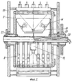
Фиг.1 - схема устройства подачи с четырьмя системами захватов листов, установленными внутри системами обработки или наблюдения и установленными снаружи пневматическими элементами и элементами проводки листов.1 is a diagram of a feed device with four sheet gripping systems installed internally by processing or surveillance systems and externally mounted pneumatic elements and sheet wiring elements.
Фиг.2 - поперечное сечение (в качестве примера) для устройства подачи на фиг.1 со схематическим изображением неподвижной центральной оси для приема установленных систем в устройстве, а также находящегося вне станины приводного колеса.FIG. 2 is a cross section (as an example) for the feeding device of FIG. 1 with a schematic illustration of a fixed central axis for receiving installed systems in the device, as well as a drive wheel located outside the bed.
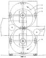
Фиг.3 - схема выполненного сдвоенным устройства подачи для нагрузки как передней стороны печатного листа, так и оборотной стороны печатного листа с установленной (в качестве примера) системой обработки и наблюдения, а также передаточный цилиндр для подачи листов.FIG. 3 is a diagram of a dual feed device for loading both the front side of a printed sheet and the reverse side of a printed sheet with an installed (as an example) processing and surveillance system, as well as a transfer cylinder for feeding sheets.
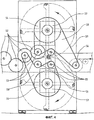
Фиг.4 - схема выполненного сдвоенным устройства подачи с зубчато-ременным приводом и расположенными в центре стойками для свободного монтажа и демонтажа приводного ремня.4 is a diagram of a dual feed device with a toothed belt drive and racks located in the center for free mounting and dismounting of the drive belt.
Фиг.5 - поперечное сечение (в качестве примера) для варианта привода с зубчато-ременным приводом на фиг.4 со схематическим изображением стойки, проведенной сбоку через приводную плоскость наружу.Figure 5 is a cross section (as an example) for a variant of the drive with a belt-belt drive in figure 4 with a schematic illustration of a rack drawn from the side through the drive plane to the outside.
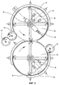
Фиг.6 - схема выполненного сдвоенным устройства подачи с установленными радиально в точках передачи листов зубчатыми с сегментами d0зубчатый сегмент < d0траектория листа для точной по регистру передачи подаваемого листа от одного устройства к следующему или на передаточный цилиндр.6 is a diagram of a double feed device with gears with segments d 0 toothed segment <d 0 a sheet path for register-accurate transfer of the fed sheet from one device to the next or to the transfer cylinder mounted radially at the sheet transfer points.
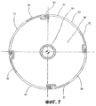
Фиг.7 - схема конструкции в виде закрытого полого цилиндра без отдельных захватных рычагов, но с радиальными выемками в боковой поверхности цилиндра для свободного доступа к обрабатываемой или наблюдаемой общей поверхности листа.7 is a design diagram in the form of a closed hollow cylinder without separate gripping arms, but with radial recesses in the side surface of the cylinder for free access to the processed or observed common surface of the sheet.
Фиг.8 - схема конструкции в виде закрытого со стороны привода и отрытого со стороны обслуживания устройства подачи для свободного бокового доступа к установленным внутри устройства системам.Fig. 8 is a design diagram in the form of a feed device closed on the drive side and open on the service side for free lateral access to systems installed inside the device.
Фиг.9 - (в качестве примера) поперечное сечение конструкции закрытого со стороны привода и открытого со стороны обслуживания устройства подачи листов на фиг.8.Fig.9 is (as an example) a cross section of the structure closed on the drive side and open on the service side of the sheet feeder in Fig.8.
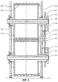
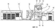
Фиг.10 - (в качестве примера) размещение установки подачи листов в сдвоенном варианте для обработки или проверки передней стороны и оборотной стороны внутри листовой печатной машины.Figure 10 - (as an example) the placement of the sheet feeder in a double version for processing or checking the front side and the reverse side inside the sheet press.
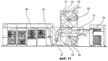
Фиг.11 - (в качестве примера) размещение установки для подачи листов в сдвоенном варианте для обработки или проверки передней и обратной стороны в виде независимо эксплуатирующейся машины для подачи листов без интегрирования в печатную машину.11 - (as an example) the placement of the installation for feeding sheets in a double version for processing or checking the front and back sides in the form of an independently operated machine for feeding sheets without integration into the printing machine.
В изображении в соответствии с фиг.1 подаваемый лист 1 перемещается системами захватов 2 по круговой траектории. Системы захватов соединены жесткими рычагами 3 захвата с пустотелым валом 4 центральной опоры 5.In the image in accordance with FIG. 1, the feed sheet 1 is moved by the gripper systems 2 along a circular path. The gripper systems are connected by
Собственно направление листа производится находящимися снаружи пневматическими элементами 6 или стержнями 7 для передачи листов. Как описано, печатный лист тем самым во время всего пути перемещения от внутреннего пространства 8 устройства имеет свободный доступ.Actually, the sheet direction is made by pneumatic elements 6 located outside or by rods 7 for sheet transfer. As described, the printed sheet is thereby freely accessible during the entire travel path from the interior space 8 of the device.
Во внутреннем пространстве изображены, например, система маркировки листов 9, система проверки листов или система наблюдения 10 с расположенным внутри освещением 11, а также система просвечивания листов или система проверки прозрачности 12 с расположенным снаружи источником света 13.In the internal space, for example, a
Посредством жесткого выполнения и расположения без зазора вращающегося устройства подачи, а также показанной на фиг.6 системы приводки подаваемый лист передается в точке передачи 14 между устройствами, а также в точке передачи 15 к передаточному цилиндру 16 с сохранением приводки от одной системы захватов на другую систему захватов, не требуя для этого дополнительных механических направляющих или стопорных элементов.By rigidly executing and locating without rotation the rotary feeding device, as well as the register system shown in FIG. 6, the feed sheet is transmitted at the transfer point 14 between the devices, as well as at the transfer point 15 to the transfer cylinder 16 while maintaining the register from one gripper system to another system captures, without requiring additional mechanical guides or locking elements.
В изображении на фиг.2 в поперечном сечении устройства подачи на фиг.1 показана неподвижная центральная ось 20, служащая для установки показанных на фиг.1 систем 9, 10, 11 и 12.In the image in figure 2 in cross section of the feeder in figure 1 shows a fixed
Специальное выполнение системы маркировки 9 служит, как изображено в данном случае, с несколькими постами маркировки для отдельной маркировки отдельных учетных единиц на печатном листе.The special implementation of the
Рычаги захвата или боковые фланцы 3 устройства охватывают, как это изображено, находящиеся внутри системы и скреплены в установленном в боковых стойках 21 полых приводных валах 22.The gripping levers or
Привод устройства подачи производится через приводной вал 22 внутри или снаружи боковой стойки с помощью зубчатых колес 23, зубчатых ремней, звездочек или других приводных средств и может быть альтернативно выполнен также как электронный непосредственный привод (в данном случае не изображен).The feed device is driven through the
Полая центральная ось 20 служит одновременно также для проводки управляющих и питающих кабелей на установленные системы.The hollow
В изображении на фиг.3 показана сдвоенная установка двух устройств подачи для следующих друг за другом обработки, наблюдения, маркировки или проверки как передней стороны 30 листа, так и оборотной стороны 31 листа.The image in figure 3 shows the dual installation of two feeders for subsequent processing, monitoring, marking or verification of both the
При этом печатный лист с первого устройства подачи 32 сначала принимается передаточным цилиндром 33 и подается системе, в данном случае изображенной, например, как камера/осветительная система 34, для нагружения передней стороны листа.In this case, the printed sheet from the
Проводка листа может, как изображено, осуществляться направляющими щитками 35 или направляющими стержнями, если под действием силы тяжести и центробежной силы обеспечивается достаточная плоскостность печатного листа на направляющем элементе.The sheet may be guided, as shown, by
Во втором устройстве подачи 36 лист затем подается во вторую систему, в данном случае она изображена в виде камеры/осветительной системы 37, для нагружения оборотной стороны листа.In the
Проводка листа производится, как изображено, вакуумными пластинами или всасывающими патрубками 38 на участке траектории листа, на котором лист должен дополнительно удерживаться с преодолением силы тяжести на направляющей плоскости. Дополнительно могут быть встроены, как в данном случае в качестве примера изображено во второй системе подачи, другие системы 39 наблюдения или проверки, например, для просвечивания листа, или системы 40 маркировки для маркировки, например, полученных в установленных системах проверки данных классификации листа.Posting of the sheet is carried out, as shown, by vacuum plates or
После прохождения второго устройства 36 подачи печатный лист передается на следующие передаточные цилиндры 41, 42, например, для дальнейшей подачи внутри печатной машины или на вывод листов.After passing through the
Все передачи листов от передаточных цилиндров в устройство подачи, а также от первого на второе устройство подачи, если не осуществляется шестеренчатый привод, синхронизированы дополнительно описанными на фиг.6 шестеренными секторами в точке передачи с обеспечением приводки.All sheet transfers from the transfer cylinders to the feeder, as well as from the first to the second feeder, if the gear drive is not carried out, are synchronized with the gear sectors at the transfer point described in FIG.
В изображении на фиг.4 привод устройства подачи листов успешно осуществляется зубчатыми ремнями 50, 51 от приводной стороны машины или приводного электродвигателя.In the image in figure 4, the drive of the sheet feeder is successfully carried out by
Это обеспечивает как экономию материала и затрат на изготовление благодаря отсутствию приводных шестерен, так и легкую возможность приведения в соответствие приводной части с монтажным положением устройств подачи и передаточных цилиндров в машине.This provides both material savings and manufacturing costs due to the absence of drive gears, as well as the easy possibility of matching the drive part with the mounting position of the feed devices and transfer cylinders in the machine.
Зубчатые колеса 52 представляют собой обычную кинематическую цепь механического привода.
С обоими вращающимися в противоположных направлениях зубчатыми колесами соединены шкивы 53 приводных ремней.
Шкивы 54 приводных ремней собственно устройств подачи могут быть выполнены, как это изображено, меньшего размера по сравнению с номинальным диаметром устройства подачи по причинам экономии места с учетом передаточного отношения.The
По натяжным роликам 55 зубчатые ремни 50, 51 могут проводиться таким образом, что несколько осей с одинаковым направлением вращения, как, например, показано в данном случае, привод второго устройства подачи, а также привода 56 передачи для первого устройства подачи соединяется только одним натяжением ремня.
В имеющей особенное преимущество конструкции боковые части стойки 57, служащие для приема неподвижных центральных осей устройств подачи, проведены на окружающем соответствующим зубчато-ременным приводом участке 58 внутри зубчато-ременной системы таким образом, что обеспечивается возможность монтажа и соответственно демонтажа зубчатого ремня без демонтажа частей стойки или разъединения жестко юстированной по причине монтированной системы центральной оси системы подачи.In a particularly advantageous construction, the lateral parts of the
В изображении на фиг.5 показано поперечное сечение приводимой зубчатыми ремнями сдвоенной установки устройства подачи на фиг.4.In the image in FIG. 5, a cross-section is shown of a dual installation of the feed device driven by toothed belts in FIG. 4.
Установка размещенных внутри устройства в данном случае не изображенных систем производится, как описано, на жесткой центральной оси 60, которая одновременно служит для проводки кабелей системы и на стороне привода установлена в соответствии с фиг.4 в деталях 57 стойки, проведенных через плоскость привода зубчатого ремня.The installation of the systems not shown in this case, which are not shown, is carried out, as described, on the rigid
Плоскость привода зубчатого ремня образована уже описанными изображенными в данном случае в разрезе зубчато-ременными шкивами и натяжными роликами 53, 54 и 55.The drive belt plane of the toothed belt is formed by the toothed belt pulleys and
Ведомое колесо зубчатой системы 52 одновременно соединено с приводным колесом 53 системы натяжения ремня.The driven wheel of the
Захватные системы 62 образуют вместе с рычагами захвата или боковыми фланцами 63 и внутренними пустотелыми валами 64 собственно жестко соединенное вращающееся устройство подачи листов.The gripping
Установка производится в подшипниках 61 качения в боковых частях 65 машины.Installation is made in rolling
В изображении на фиг.6, как уже описано, производится точная по приводке синхронизация систем захвата устройства подачи относительно друг друга, а также относительно передаточных цилиндров посредством зубчатых секторов 70.In the image in FIG. 6, as already described, register-accurate locking of the gripper systems of the feed device relative to each other, as well as relative to the transfer cylinders by means of
Они расположены по сторонам на периферии устройства подачи таким образом, что к каждой системе захвата листов относится соответствующий зубчатый сектор, выровненный по средней оси (центральной оси) передачи листов.They are located on the sides on the periphery of the feeder in such a way that each sheet gripping system has a corresponding gear sector aligned with the center axis (central axis) of the sheet transfer.
Диаметр 71 градуированного круга зубчатых сегментов 70 несколько меньше номинального диаметра 72 устройства подачи так, что при приближении двух зубчатых сегментов друг к другу вначале производится вхождение в зубчатое зацепление с относительно большим зазором между зубьями.The
При дальнейшем движении к точке передачи листов зазор между зубьями уменьшается в соответствии со сближением обоих диаметров 71 и 72 до юстированного минимального зазора в точке передачи листа, которая одновременно представляет собой тангенциальную точку касания диаметров 71 и 72.With further movement to the sheet transfer point, the gap between the teeth decreases in accordance with the approximation of both
Для каждой передачи листов таким образом осуществляется полный цикл выравнивания и приводки, который обеспечивает точную по регистру передачу листов даже при возможных колебаниях приводки по окружности со стороны привода, например, вследствие упругости примененного привода.For each sheet transfer, a complete alignment and register cycle is thus carried out, which ensures register-accurate sheet transfer even with possible register fluctuations around the circumference of the drive, for example, due to the elasticity of the drive used.
Особенное технологическое преимущество примененного зубчатого сегмента 70 заключается в том, что эти сегменты представляют собой только вырезы из обычно и недорого изготавливаемых геометрических зубчатых зацеплений, и все-таки обеспечивается непрерывно уменьшающийся и вновь увеличивающийся зазор между зубьями для выполнения процесса приводки без необходимости учета этой разности в зазорах между зубьями, например, во время изготовления зубчатых зацеплений.A particular technological advantage of the used
Кроме того, зубчатые сегменты перераспределены на устройстве подачи с радиальным перемещением таким образом, что можно простым образом обеспечить приводку передачи листов путем юстировки взаимно зацепленных зубчатых сегментов до минимального зазора между зубьями в точке передачи.In addition, the gear segments are redistributed on the feed device with radial movement in such a way that the sheet transfer register can be easily secured by adjusting the mutually engaged gear segments to a minimum gap between the teeth at the transmission point.
В изображении на фиг.7 показана альтернативная конструкция устройства подачи листов в виде цилиндрического тела.The image in FIG. 7 shows an alternative construction of a sheet feeding device in the form of a cylindrical body.
Цилиндр подачи листов в данном случае состоит из полого вала или фланца 80 для приема опоры или двух боковых стенок 81 вместо отдельных рычагов захвата, а также цилиндрической боковой поверхности 82 вместо отдельных поперечин захватов.The sheet feeding cylinder in this case consists of a hollow shaft or
В соответствии с обычным прижимным или передаточным цилиндром в боковой поверхности цилиндра встроены системы захвата листов.According to a conventional pressure or transfer cylinder, sheet gripping systems are integrated in the side surface of the cylinder.
Однако боковая поверхность цилиндра имеет на каждый подаваемый лист по одному вырезу 84, который обеспечивает доступ к поверхности листа с внутренней стороны устройства подачи, по меньшей мере, на участке проводимых процессов наблюдения, обработки, маркировки, считывания или проверки.However, the side surface of the cylinder has one
Если размеры цилиндра подачи выбраны таким образом, что окружное деление на некоторую величину превышает длину листа или отрезка листа, то вследствие оставшихся боковых поверхностей - перемычки 85, создается устойчивая против скручивающих усилий и одновременно с преимуществом изготавливаемая конструкция, имеющая функциональные свойства описанного изобретения.If the dimensions of the feed cylinder are selected in such a way that the circumferential division exceeds the length of the sheet or the length of the sheet by some amount, then due to the remaining side surfaces,
В описании в соответствии с фиг.8 показан особенно благоприятный для монтажа, обслуживания и управления вариант выполнения, который доступен со стороны обслуживания (в данном случае вид спереди).In the description in accordance with FIG. 8, an embodiment which is particularly suitable for installation, maintenance and control is shown, which is accessible from the service side (in this case, a front view).
Все элементы установки, управления и привода уже описанным образом скомпонованы на приводной стороне 90.All elements of the installation, control and drive are already described in a way arranged on the
С показанной в данном случае стороны обслуживания осуществляется установка вращающегося устройства подачи через установленное приблизительно на номинальный диаметр траектории листа опорное кольцо 91, которое проведено по установленным в боковых стойках стороны обслуживания опорным роликам или элементам позиционирования 92.On the service side shown in this case, a rotary feed device is installed through a
Тем самым поверхность 93 внутри контрольного кольца 91 становится свободной от элементов позиционирования и прочих элементов и может служить для свободного доступа к системам, установленным во внутреннем пространстве устройства. Боковые стойки 94 стороны управления имеют на этом участке соответствующие выемки. Так как этот доступ имеется также и в рабочем состоянии установки, со стороны обслуживания можно установить также стопорные устройства или устройства снабжения для рабочих систем или установить приспособления, обеспечивающие боковой вывод систем из рабочего положения в положение обслуживания.Thus, the
В изображении на фиг.9 показано в качестве примера поперечное сечение описанной на фиг.8 конструкции с открытой с одной стороны стороной обслуживания.In the image in FIG. 9, an example is a cross-section of the structure described in FIG. 8 with the service side open on one side.
На данном виде не изображены системы, устанавливаемые во внутреннем пространстве.This view does not depict systems installed in the interior.
Боковая стойка 100 стороны привода служит для приема элемента опоры 101 для основной опоры 102 устройства подачи листов. На приводном фланце 103 установлено изображенное в данном случае в виде лобового зубчатого колеса приводное колесо 104.The side stand 100 of the drive serves to receive the
Посредством передаточных элементов, в данном случае, например, зубчатого ремня 105, зубчатых шкивов 106 и зубчатых колес 107, осуществляется, как уже описано, привод устройства подачи.By means of transmission elements, in this case, for example, a
Точно так же все элементы управления, например дисковые кулачки (в данном случае не изображены) для управления систем захватов листов 109 устройства подачи, установлены на контактных роликах 108 на стороне привода. Кроме того, сама механически закрытая или несущая часть 110 устройства подачи находится на стороне привода.Similarly, all controls, such as disk cams (not shown in this case) for controlling the
На стороне обслуживания производится установка на контрольное кольцо 111, установленное приблизительно на номинальном диаметре траектории листа, которое может быть выполнено в виде наружного или внутреннего контрольного кольца, а также на установленные в боковой стойке контактные ролики 112.On the service side, installation is made on the
Боковая стойка 113 стороны обслуживания открыта внутри описываемой контрольным кольцом 111 поверхности для того, чтобы обеспечить через служебное отверстие 114 свободный доступ к установленным во внутреннем пространстве системам.The side stand 113 of the service side is open inside the surface described by the
Кроме того, для того чтобы обеспечить несущее с обеих сторон крепление рабочих систем, выполнен также противолежащий приводной фланец 103 в виде полого вала.In addition, in order to ensure the fastening of the working systems on both sides, an opposing
Через отверстие 116 фланца можно с успехом, например, провести стопорные поперечины или установочные элементы с целью жесткого со стороны привода крепления в направлении к боковой стойке наружу.Through the
В изображении на фиг.10 устройство подачи листов как функциональная составная часть интегрировано в имеющуюся листовую машину.In the image in FIG. 10, the sheet feeder as a functional component is integrated into an existing sheet machine.
От наклада 120 через барабан 121 приводки лист проводится с сохранением приводки по окружности и поперечной приводки направления подачи листов.From the
Изображенное в данном случае в качестве примера устройство подачи позволяет в своем агрегате 122 передних сторон создать нагрузки на переднюю сторону листа, а также в агрегате 123 оборотных сторон - нагрузки на оборотную сторону листа в соответствии с изобретением.The feed device shown in this case as an example allows one to create loads on the front side of the sheet in its
Полученные с помощью установленных или нанесенных в устройстве подачи листов систем 124, 125, 126, 127 данные или маркировки могут быть успешно использованы в изображенном в данном случае устройстве для того, чтобы управлять другими процессами изготовления или сортировки в последующих печатающих агрегатах или агрегатах вывода листов, прерывать их или изменять. На основании сохраняющей в соответствии с изобретением приводку подачи листов в устройстве подачи листов печатный лист может передаваться далее через передаточный цилиндр, то есть без дальнейшего механического выравнивания листа, например, на листовую печатную машину 128.The data or markings obtained using the
Кроме того, в маркирующем приспособлении 129 создаваемые установленными в устройстве подачи листов системами и передаваемые данные о листах передаются в виде читаемой или кодированной информации, например, с помощью чернильного печатающего устройства или системы для контроля красок на печатный лист.In addition, in the
В надлежащем варианте выполнения маркирующее приспособление 129 может служить также для маркировки печатных листов или отдельных тетрадей посредством нанесения распознаваемого или считываемого машиной символа, например цветного столбика, или обозначать особым образом.In an appropriate embodiment, the marking
Сортировка изготовленных печатных листов может производиться в выводе листов 130 с несколькими стопками листов в зависимости от классификации продукции, полученной установленными в устройстве подачи 122, 123 системами 124, 125, 126, 127 или от выполненного на посту маркировки 129 обозначения.Sorting of the printed sheets made can be carried out in the output of
В изображении на фиг.11 устройство подачи листов показано в виде основного агрегата самостоятельно эксплуатируемой листовой печатной машины.In the image of FIG. 11, the sheet feeder is shown as the main unit of a self-operated sheet-fed printing press.
Компоненты тетрадей 120, 121, а также устройство подачи 122, 123 и их рабочие системы 124, 125, 126, 127 при этом соответствуют изображенной на фиг.10 установке.The components of
Но затем в печатном агрегате не производится никакого процесса производства или печатания, а производится непосредственная передача подаваемого листа на вывод листов 130 с уже описанными на фиг.10 функциями и, например, со встроенным постом маркировки 129.But then, in the printing unit, no production or printing process is carried out, but the feed sheet is directly transferred to the output of
Для привода устройства подачи, а также вывода листов в листовую машину встроена приводная часть 131. Основная функция изображенной конструкции заключается тем самым в процессах подачи, обработки, наблюдения, маркировки и проверки листов, проходящих раздельно от других производственных процессов.To drive the feeder, as well as the output of the sheets, a
Claims (16)
Applications Claiming Priority (2)
| Application Number | Priority Date | Filing Date | Title |
|---|---|---|---|
| CH9072000 | 2000-05-08 | ||
| CH907/00 | 2000-05-08 |
Publications (2)
| Publication Number | Publication Date |
|---|---|
| RU2002132887A RU2002132887A (en) | 2004-04-20 |
| RU2248317C2 true RU2248317C2 (en) | 2005-03-20 |
Family
ID=4546994
Family Applications (1)
| Application Number | Title | Priority Date | Filing Date |
|---|---|---|---|
| RU2002132887/12A RU2248317C2 (en) | 2000-05-08 | 2001-04-30 | Sheet material advancing device |
Country Status (12)
| Country | Link |
|---|---|
| US (1) | US20040026851A1 (en) |
| EP (1) | EP1280724B1 (en) |
| JP (1) | JP2004517787A (en) |
| KR (1) | KR20030007585A (en) |
| CN (1) | CN1427793A (en) |
| AT (1) | ATE276188T1 (en) |
| AU (2) | AU2001250232B2 (en) |
| CA (1) | CA2407844A1 (en) |
| DE (1) | DE50103633D1 (en) |
| RU (1) | RU2248317C2 (en) |
| UA (1) | UA74581C2 (en) |
| WO (1) | WO2001085586A1 (en) |
Cited By (4)
| Publication number | Priority date | Publication date | Assignee | Title |
|---|---|---|---|---|
| RU2347676C2 (en) * | 2007-04-12 | 2009-02-27 | Геннадий Кузьмич Микрюков | Stone-working machine on aerostatic supports |
| RU2348521C2 (en) * | 2007-04-12 | 2009-03-10 | Микрюков Геннадий Кузьмич | Duplex module for blank rotation and regular feed enabling simultaneous treatment of both free ends of blank |
| RU2348522C1 (en) * | 2007-06-04 | 2009-03-10 | Геннадий Кузьмич Микрюков | Multiple-disk stone-milling machine tool equipped with duplex module for blank rotation and regular feed |
| RU2371294C2 (en) * | 2007-06-04 | 2009-10-27 | Геннадий Кузьмич Микрюков | Detachable device for fixation of flat stocks |
Families Citing this family (21)
| Publication number | Priority date | Publication date | Assignee | Title |
|---|---|---|---|---|
| JP4616451B2 (en) † | 2000-09-22 | 2011-01-19 | 株式会社小森コーポレーション | Print quality inspection device |
| DE10217403A1 (en) * | 2001-12-18 | 2003-07-10 | Koenig & Bauer Ag | Material control device |
| DE10234084B4 (en) * | 2002-07-26 | 2006-06-14 | Koenig & Bauer Ag | Device for inspection of sheet material |
| DE10242398B4 (en) * | 2002-09-12 | 2007-03-22 | Giesecke & Devrient Gmbh | Device for checking the condition of banknotes |
| DE10306442B4 (en) * | 2003-02-17 | 2012-04-19 | Eastman Kodak Co. | Method and device for determining possible displacements of a printing material on a conveyor belt |
| DE10332211B3 (en) * | 2003-07-16 | 2005-02-10 | Koenig & Bauer Ag | Machine for processing sheets |
| EP1589495A1 (en) | 2004-04-22 | 2005-10-26 | Kba-Giori S.A. | Inspection machine and process |
| EP1588864A1 (en) | 2004-04-22 | 2005-10-26 | Kba-Giori S.A. | Printing machine with laser perforating unit |
| ITMI20041054A1 (en) * | 2004-05-26 | 2004-08-26 | Riparazioni Macchine Grafi Ce | VERIFICATION EQUIPMENT FOR VALUE SHEETS AND RELATED METHOD OF CONTROL OF A PRINTING MACHINE |
| DE102005037497A1 (en) * | 2005-08-09 | 2007-02-15 | Man Roland Druckmaschinen Ag | Method for individually characterizing each copy on a printed sheet comprises applying a printing ink or coating on the sheet using a printing device connected to a laser device with a thermosensitive ink |
| DE102005043241A1 (en) * | 2005-09-09 | 2007-03-15 | Man Roland Druckmaschinen Ag | Method and device for marking sheet material in a processing machine |
| DE102006006676A1 (en) * | 2006-02-14 | 2007-08-23 | Koenig & Bauer Aktiengesellschaft | Sheet- |
| EP1834779A1 (en) * | 2006-03-14 | 2007-09-19 | Kba-Giori S.A. | Inspection system for a sheet-fed recto-verso printing press |
| DE102007036326B4 (en) | 2006-08-02 | 2024-09-19 | Koenig & Bauer Ag | Device and method for marking and separating faulty print images |
| EP1980393A1 (en) | 2007-04-13 | 2008-10-15 | Kba-Giori S.A. | Method and system for producing notes of securities |
| DE102007035435B4 (en) * | 2007-07-28 | 2009-04-16 | WINKLER+DüNNEBIER AG | Apparatus and method for drawing flat pieces of material and register-accurate transporting the flat pieces of material |
| EP2189407A1 (en) | 2008-11-21 | 2010-05-26 | Kba-Giori S.A. | Method and system for processing printed sheets, especially sheets of printed securities, into individual documents |
| DE102010012951A1 (en) | 2010-03-26 | 2011-09-29 | Siemens Aktiengesellschaft | Device for generating image of movable article i.e. mail, has transparent region completely filled with pane or film, which are transparent and impervious for solid and powdery substances |
| CN102610029B (en) | 2012-03-09 | 2014-02-12 | 广州广电运通金融电子股份有限公司 | Identification device for paper with value |
| CN103303708A (en) * | 2013-05-20 | 2013-09-18 | 浙江华岳包装机械有限公司 | Automatic picking and placing mechanism for film pasting of visible window of package box |
| EP2902210A1 (en) | 2014-02-04 | 2015-08-05 | KBA-NotaSys SA | Multicolour letterpress printing press having numbering cylinders and an additional printing unit |
Citations (4)
| Publication number | Priority date | Publication date | Assignee | Title |
|---|---|---|---|---|
| GB2073986A (en) * | 1980-03-29 | 1981-10-21 | Triumph Adler Buero Inf | Copying system |
| RU2053886C1 (en) * | 1991-08-14 | 1996-02-10 | Кениг унд Бауер АГ | Device to control printed sheets in printing machine |
| EP0773661A1 (en) * | 1995-11-13 | 1997-05-14 | Agfa-Gevaert N.V. | Rotating drum imagesetter |
| EP0818307A1 (en) * | 1996-07-07 | 1998-01-14 | Scitex Corporation Ltd. | Internal rotating drum plotter |
Family Cites Families (13)
| Publication number | Priority date | Publication date | Assignee | Title |
|---|---|---|---|---|
| US2765735A (en) * | 1951-12-21 | 1956-10-09 | Ibm | Selective printing machine for printing both sides of a bill |
| US3772990A (en) * | 1971-05-27 | 1973-11-20 | Miller Printing Machinery Co | Sheet handling apparatus for a printing press |
| US3884146A (en) * | 1972-01-20 | 1975-05-20 | Harris Intertype Corp | Printing press with sheet turnover mechanism |
| US4099463A (en) * | 1977-04-13 | 1978-07-11 | Veb Polygraph Leipzig Kombinat Fuer Polygraphische Maschinen Und Ausruestungen | Support arrangement for guiding sheets through a printing machine |
| US4918466A (en) * | 1984-03-22 | 1990-04-17 | Canon Kabushiki Kaisha | Light beam image recording apparatus having commonly driven member |
| US4731863A (en) * | 1986-04-07 | 1988-03-15 | Eastman Kodak Company | Digital image processing method employing histogram peak detection |
| AU651544B2 (en) * | 1992-03-03 | 1994-07-21 | Kba-Notasys Sa | Device for conveying printed sheets in an installation for checking the quality of paper money |
| DE19708213A1 (en) * | 1996-04-09 | 1997-10-30 | Heidelberger Druckmasch Ag | Method and device for product guidance in a fold formation area of a folding apparatus |
| DE19624196C2 (en) * | 1996-06-18 | 1999-09-23 | Koenig & Bauer Ag | Device and method for sheet guidance in a qualitative assessment of processed sheets |
| DE19707657A1 (en) * | 1997-02-26 | 1998-09-10 | Heidelberger Druckmasch Ag | Sheet sensor for sheet printer with hollow cylindrical drum |
| WO1999011551A1 (en) * | 1997-09-04 | 1999-03-11 | Xaar Technology Limited | Vacuum drums for printing, and duplex printers |
| US6344904B1 (en) * | 1998-10-03 | 2002-02-05 | John E. Mercer | Arrangement for reading from and/or writing to flexible sheet media in a curved configuration and method |
| US6585263B1 (en) * | 2000-02-02 | 2003-07-01 | Heidelberger Druckmaschinen Ag | Deceleration drum assembly containing air guides |
-
2001
- 2001-04-30 US US10/275,442 patent/US20040026851A1/en not_active Abandoned
- 2001-04-30 UA UA2002129792A patent/UA74581C2/en unknown
- 2001-04-30 EP EP01923459A patent/EP1280724B1/en not_active Expired - Lifetime
- 2001-04-30 RU RU2002132887/12A patent/RU2248317C2/en not_active IP Right Cessation
- 2001-04-30 WO PCT/CH2001/000270 patent/WO2001085586A1/en not_active Ceased
- 2001-04-30 CN CN01809181A patent/CN1427793A/en active Pending
- 2001-04-30 AU AU2001250232A patent/AU2001250232B2/en not_active Ceased
- 2001-04-30 JP JP2001582197A patent/JP2004517787A/en active Pending
- 2001-04-30 DE DE50103633T patent/DE50103633D1/en not_active Expired - Fee Related
- 2001-04-30 AT AT01923459T patent/ATE276188T1/en not_active IP Right Cessation
- 2001-04-30 KR KR1020027014872A patent/KR20030007585A/en not_active Withdrawn
- 2001-04-30 CA CA002407844A patent/CA2407844A1/en not_active Abandoned
- 2001-04-30 AU AU5023201A patent/AU5023201A/en active Pending
Patent Citations (4)
| Publication number | Priority date | Publication date | Assignee | Title |
|---|---|---|---|---|
| GB2073986A (en) * | 1980-03-29 | 1981-10-21 | Triumph Adler Buero Inf | Copying system |
| RU2053886C1 (en) * | 1991-08-14 | 1996-02-10 | Кениг унд Бауер АГ | Device to control printed sheets in printing machine |
| EP0773661A1 (en) * | 1995-11-13 | 1997-05-14 | Agfa-Gevaert N.V. | Rotating drum imagesetter |
| EP0818307A1 (en) * | 1996-07-07 | 1998-01-14 | Scitex Corporation Ltd. | Internal rotating drum plotter |
Cited By (4)
| Publication number | Priority date | Publication date | Assignee | Title |
|---|---|---|---|---|
| RU2347676C2 (en) * | 2007-04-12 | 2009-02-27 | Геннадий Кузьмич Микрюков | Stone-working machine on aerostatic supports |
| RU2348521C2 (en) * | 2007-04-12 | 2009-03-10 | Микрюков Геннадий Кузьмич | Duplex module for blank rotation and regular feed enabling simultaneous treatment of both free ends of blank |
| RU2348522C1 (en) * | 2007-06-04 | 2009-03-10 | Геннадий Кузьмич Микрюков | Multiple-disk stone-milling machine tool equipped with duplex module for blank rotation and regular feed |
| RU2371294C2 (en) * | 2007-06-04 | 2009-10-27 | Геннадий Кузьмич Микрюков | Detachable device for fixation of flat stocks |
Also Published As
| Publication number | Publication date |
|---|---|
| EP1280724B1 (en) | 2004-09-15 |
| US20040026851A1 (en) | 2004-02-12 |
| AU2001250232B2 (en) | 2005-07-14 |
| CA2407844A1 (en) | 2002-10-31 |
| CN1427793A (en) | 2003-07-02 |
| ATE276188T1 (en) | 2004-10-15 |
| EP1280724A1 (en) | 2003-02-05 |
| UA74581C2 (en) | 2006-01-16 |
| DE50103633D1 (en) | 2004-10-21 |
| JP2004517787A (en) | 2004-06-17 |
| WO2001085586A1 (en) | 2001-11-15 |
| KR20030007585A (en) | 2003-01-23 |
| AU5023201A (en) | 2001-11-20 |
Similar Documents
| Publication | Publication Date | Title |
|---|---|---|
| RU2248317C2 (en) | Sheet material advancing device | |
| US7096784B2 (en) | Installation for treating sheets of printed paper | |
| US5979316A (en) | Belt-driven printer-cutter machine for corrugated paperboard of varying thickness | |
| RU2002132887A (en) | SHEET FEEDING DEVICE | |
| US6684772B2 (en) | Flexographic printing machine | |
| CN116568514B (en) | Sheet-fed printing unit and method for operating a sheet-fed printing unit | |
| US8469647B2 (en) | Book binding machine | |
| RU2616908C2 (en) | Printing machine for intaglio print | |
| US6832758B2 (en) | Mobile feeder system | |
| CN102126341A (en) | Apparatus for correcting the position of sheets | |
| CN116568513B (en) | Sheet-fed printing unit with two base modules, designed as a screen printing unit | |
| DE102004050725B4 (en) | Method for transporting sheet material and processing machine thereto | |
| CN116368012B (en) | Sheet-fed printing unit configured as screen printing unit | |
| US20090071353A1 (en) | Flexographic printer | |
| US534298A (en) | Printing-machine | |
| GB2168041A (en) | Turning over sheets in printing equipment | |
| DE102006051279A1 (en) | Device and method for finishing sheet-shaped substrates | |
| GB2277903A (en) | Changing roller-mounted printing plates | |
| CN120916899A (en) | Sheet-fed printing press with simultaneous printing inspection device | |
| EP2230200A2 (en) | Device for conveying a sheet |
Legal Events
| Date | Code | Title | Description |
|---|---|---|---|
| MM4A | The patent is invalid due to non-payment of fees |
Effective date: 20060501 |