RU2248261C1 - Hacksaw blade - Google Patents
Hacksaw blade Download PDFInfo
- Publication number
- RU2248261C1 RU2248261C1 RU2003119078/02A RU2003119078A RU2248261C1 RU 2248261 C1 RU2248261 C1 RU 2248261C1 RU 2003119078/02 A RU2003119078/02 A RU 2003119078/02A RU 2003119078 A RU2003119078 A RU 2003119078A RU 2248261 C1 RU2248261 C1 RU 2248261C1
- Authority
- RU
- Russia
- Prior art keywords
- teeth
- group
- tooth
- divorce
- saw
- Prior art date
Links
- 208000002925 dental caries Diseases 0.000 claims description 6
- 230000000694 effects Effects 0.000 abstract description 8
- 239000000126 substance Substances 0.000 abstract 1
- 238000005520 cutting process Methods 0.000 description 157
- 239000011343 solid material Substances 0.000 description 27
- 238000000034 method Methods 0.000 description 11
- 238000010276 construction Methods 0.000 description 5
- 230000004048 modification Effects 0.000 description 4
- 238000012986 modification Methods 0.000 description 4
- 239000002184 metal Substances 0.000 description 3
- 229910000831 Steel Inorganic materials 0.000 description 2
- 239000000463 material Substances 0.000 description 2
- 239000010959 steel Substances 0.000 description 2
- 238000013459 approach Methods 0.000 description 1
- 238000005452 bending Methods 0.000 description 1
- 238000004140 cleaning Methods 0.000 description 1
- 239000000470 constituent Substances 0.000 description 1
- 238000003754 machining Methods 0.000 description 1
- 230000003252 repetitive effect Effects 0.000 description 1
- 229910001220 stainless steel Inorganic materials 0.000 description 1
- 239000010935 stainless steel Substances 0.000 description 1
Images


Classifications
-
- B—PERFORMING OPERATIONS; TRANSPORTING
- B23—MACHINE TOOLS; METAL-WORKING NOT OTHERWISE PROVIDED FOR
- B23D—PLANING; SLOTTING; SHEARING; BROACHING; SAWING; FILING; SCRAPING; LIKE OPERATIONS FOR WORKING METAL BY REMOVING MATERIAL, NOT OTHERWISE PROVIDED FOR
- B23D61/00—Tools for sawing machines or sawing devices; Clamping devices for these tools
- B23D61/12—Straight saw blades; Strap saw blades
- B23D61/121—Types of set; Variable teeth, e.g. variable in height or gullet depth; Varying pitch; Details of gullet
-
- B—PERFORMING OPERATIONS; TRANSPORTING
- B23—MACHINE TOOLS; METAL-WORKING NOT OTHERWISE PROVIDED FOR
- B23D—PLANING; SLOTTING; SHEARING; BROACHING; SAWING; FILING; SCRAPING; LIKE OPERATIONS FOR WORKING METAL BY REMOVING MATERIAL, NOT OTHERWISE PROVIDED FOR
- B23D61/00—Tools for sawing machines or sawing devices; Clamping devices for these tools
- B23D61/02—Circular saw blades
- B23D61/021—Types of set; Variable teeth, e.g. variable in height or gullet depth; Varying pitch; Details of gullet
-
- Y—GENERAL TAGGING OF NEW TECHNOLOGICAL DEVELOPMENTS; GENERAL TAGGING OF CROSS-SECTIONAL TECHNOLOGIES SPANNING OVER SEVERAL SECTIONS OF THE IPC; TECHNICAL SUBJECTS COVERED BY FORMER USPC CROSS-REFERENCE ART COLLECTIONS [XRACs] AND DIGESTS
- Y10—TECHNICAL SUBJECTS COVERED BY FORMER USPC
- Y10T—TECHNICAL SUBJECTS COVERED BY FORMER US CLASSIFICATION
- Y10T83/00—Cutting
- Y10T83/929—Tool or tool with support
- Y10T83/9319—Toothed blade or tooth therefor
- Y10T83/9346—Uniformly varying teeth or tooth spacing
-
- Y—GENERAL TAGGING OF NEW TECHNOLOGICAL DEVELOPMENTS; GENERAL TAGGING OF CROSS-SECTIONAL TECHNOLOGIES SPANNING OVER SEVERAL SECTIONS OF THE IPC; TECHNICAL SUBJECTS COVERED BY FORMER USPC CROSS-REFERENCE ART COLLECTIONS [XRACs] AND DIGESTS
- Y10—TECHNICAL SUBJECTS COVERED BY FORMER USPC
- Y10T—TECHNICAL SUBJECTS COVERED BY FORMER US CLASSIFICATION
- Y10T83/00—Cutting
- Y10T83/929—Tool or tool with support
- Y10T83/9319—Toothed blade or tooth therefor
- Y10T83/9348—Undulating tooth arrangement
-
- Y—GENERAL TAGGING OF NEW TECHNOLOGICAL DEVELOPMENTS; GENERAL TAGGING OF CROSS-SECTIONAL TECHNOLOGIES SPANNING OVER SEVERAL SECTIONS OF THE IPC; TECHNICAL SUBJECTS COVERED BY FORMER USPC CROSS-REFERENCE ART COLLECTIONS [XRACs] AND DIGESTS
- Y10—TECHNICAL SUBJECTS COVERED BY FORMER USPC
- Y10T—TECHNICAL SUBJECTS COVERED BY FORMER US CLASSIFICATION
- Y10T83/00—Cutting
- Y10T83/929—Tool or tool with support
- Y10T83/9319—Toothed blade or tooth therefor
- Y10T83/935—Plural tooth groups
- Y10T83/9353—Including raker tooth group
-
- Y—GENERAL TAGGING OF NEW TECHNOLOGICAL DEVELOPMENTS; GENERAL TAGGING OF CROSS-SECTIONAL TECHNOLOGIES SPANNING OVER SEVERAL SECTIONS OF THE IPC; TECHNICAL SUBJECTS COVERED BY FORMER USPC CROSS-REFERENCE ART COLLECTIONS [XRACs] AND DIGESTS
- Y10—TECHNICAL SUBJECTS COVERED BY FORMER USPC
- Y10T—TECHNICAL SUBJECTS COVERED BY FORMER US CLASSIFICATION
- Y10T83/00—Cutting
- Y10T83/929—Tool or tool with support
- Y10T83/9319—Toothed blade or tooth therefor
- Y10T83/9358—Series of dissimilar teeth
Landscapes
- Engineering & Computer Science (AREA)
- Mechanical Engineering (AREA)
- Sawing (AREA)
- Treatment Of Fiber Materials (AREA)
- Gears, Cams (AREA)
- Turbine Rotor Nozzle Sealing (AREA)
Abstract
Description
Область техники, к которой относится изобретениеFIELD OF THE INVENTION
Изобретение относится к ножовочному полотну, например, для ленточной пилы, ножовочного станка, дисковой пилы и аналогичных устройств, используемых в качестве инструментов для разрезания материала (заготовки).The invention relates to a hacksaw blade, for example, for a bandsaw, hacksaw, circular saw and similar devices used as tools for cutting material (workpiece).
Предшествующий уровень техникиState of the art
Ленточно-отрезной станок обычно используют в качестве устройства для разрезания крупной металлической заготовки. Чтобы уменьшить вибрации или шумы, в ножовочном полотне, используемом в ленточно-отрезном станке, реализуют разнообразные схемы развода, например схему с одним зубом, разведенным вправо, одним зубом, разведенным влево, и одним зубом без развода, схему волнообразного развода и схему прямоугольного развода, а шаг между зубьями делают неравномерным. Чтобы справиться с трудностями, возникающими при обработке на станке такого материала, как нержавеющая сталь, разработано ножовочное полотно, в котором высота большого количества зубьев ножовочного полотна выполнена переменной или выполнена переменной степень развода большого количества разведенных зубьев.A band saw is usually used as a device for cutting large metal workpieces. To reduce vibrations or noise, a variety of divorce schemes are implemented in the hacksaw blade used in the band saw machine, for example, a scheme with one tooth divorced to the right, one tooth divorced to the left, and one tooth without a divorce, a wave-like divorce scheme and a rectangular divorce scheme , and the step between the teeth is made uneven. To cope with the difficulties encountered when machining a material such as stainless steel, a hacksaw blade has been developed in which the height of a large number of teeth of a hacksaw blade is made variable or the degree of divorce of a large number of diluted teeth is made variable.
Для удовлетворения запросов промышленности разработаны разнообразные ножовочные полотна, например ножовочное полотно, в котором углы вершин зубьев пилы изменяются различным образом, в котором обратная поверхность ножовочного полотна выполнена волнистой или в котором кривые линии, соединяющие вершины зубьев ножовочного полотна, выполнены волнистыми.To meet the demands of the industry, various hacksaw blades have been developed, for example, a hacksaw blade in which the angles of the saw tooth tips vary in different ways, in which the back surface of the hacksaw blade is made wavy or in which the curved lines connecting the tops of the teeth of the hacksaw blade are made wavy.
Что касается ленточно-отрезного станка для разрезания металлической заготовки, то, например, также разработаны разнообразные ленточно-отрезные станки и соответствующие способы осуществления процессов резания. Например, способы резания на ленточно-отрезных станках приближенно подразделяются на два вида, а именно, относящиеся (1) к случаю, когда скорость резания является постоянной независимо от длины резания заготовки, и (2) к случаю, когда скорость резания изменяется в соответствии с длиной резания заготовки.As for the band-cutting machine for cutting a metal billet, for example, a variety of band-cutting machines and the corresponding methods for carrying out cutting processes have also been developed. For example, cutting methods on tape-cutting machines are approximately divided into two types, namely, related to (1) the case when the cutting speed is constant regardless of the length of the workpiece, and (2) the case when the cutting speed changes in accordance with cutting length of the workpiece.
Способы (2), в которых скорость резания изменяется в соответствии с длиной резания заготовки, могут быть дополнительно подразделены на:Methods (2), in which the cutting speed varies in accordance with the cutting length of the workpiece, can be further divided into:
(2-1) способ с регулированием противодавления, создающегося в цилиндре, в том случае, когда используют гидравлический цилиндр,(2-1) a method for controlling backpressure generated in a cylinder when a hydraulic cylinder is used,
(2-2) способ с регулированием скорости потока в соответствии с сопротивлением резанию, в том случае, когда используют гидравлический цилиндр,(2-2) a method with controlling the flow rate in accordance with the resistance to cutting, in the case when using a hydraulic cylinder,
(2-3) способ числового программного управления, в котором форма заготовки является заранее известной входной величиной, при этом длину резания заготовки рассчитывают в каждый момент времени, а скорость резания изменяют,(2-3) a method of numerical program control, in which the shape of the workpiece is a predetermined input value, while the cutting length of the workpiece is calculated at each time point, and the cutting speed is changed,
(2-4) способ числового программного управления, в котором измеряют сопротивление резанию, а скорость резания изменяют в соответствии с сопротивлением резанию,(2-4) a numerical control method in which a cutting resistance is measured, and a cutting speed is changed in accordance with a cutting resistance,
(2-5) способ, в котором массу крепежной рамы, в которой установлено ножовочное полотно, механически регулируют и ограничивают, а заготовку разрезают в режиме свободного опускания ножовочного полотна.(2-5) a method in which the mass of the mounting frame in which the hacksaw blade is installed is mechanically adjusted and limited, and the workpiece is cut in the free lowering mode of the hacksaw blade.
Традиционно широко используют ленточно-отрезной станок, выполненный в виде небольшой и недорогой переносной ленточной пилы. Обычно небольшая переносная ленточная пила и ленточная пила поперечного типа являются пилами шарнирного типа, в которых крепежная рама ножовочного полотна качается в вертикальном направлении так, что описывает дугу, и в них часто используют способ (2-5). Далее в этом описании такой ленточно-отрезной станок будет называться “пильным станком небольшой нагрузки”.Traditionally widely used tape cutting machine, made in the form of a small and inexpensive portable band saw. Typically, a small portable band saw and a cross-type band saw are articulated saws in which the hacksaw blade mounting frame swings in the vertical direction so as to describe the arc, and the method is often used in them (2-5). Further in this description, such a band saw will be called a “light load saw machine”.
Имеющиеся в широкой продаже пильные станки небольшой нагрузки пригодны для разрезания относительно небольших заготовок при осуществлении процесса резания на площадке для сооружения стальной конструкции. Хотя образцы таких заготовок ограничены небольшими объектами, но виды образцов заготовок весьма разнообразны, и поэтому осуществляют процессы резания таких заготовок, как стальные объекты различной формы, трубы и сплошные материалы небольшого диаметра.Commercially available light duty saws are suitable for cutting relatively small workpieces during the cutting process at the site for steel structure construction. Although the samples of such blanks are limited to small objects, the types of samples of the blanks are very diverse, and therefore they carry out cutting processes for such blanks as steel objects of various shapes, pipes and solid materials of small diameter.
Как показано на фиг.1А и 1В, в пильных станках небольшой нагрузки, описанных выше, одна схема развода содержит три зуба, а именно один зуб S без развода и пару зубьев L и R с разводом влево и вправо, имеющих постоянную степень развода в поперечном направлении, и эта схема развода выполнена повторяющейся. Когда необходимо разрезать сплошной материал W, имеющий диаметр 50 мм, то, используя ножовочное полотно 101, имеющее шаг зубьев 4 мм, показанный на фиг.3, можно осуществить соответствующий процесс резания. Однако, когда необходимо разрезать трубу W, имеющую диаметр 50 мм и толщину стенки 3 мм, то при использовании того же самого ножовочного полотна 101, показанного на фиг. 4, возникает проблема, заключающаяся в предрасположенности ножовочного полотна 101 к разрушению.As shown in FIGS. 1A and 1B, in light load sawing machines described above, one divorce pattern contains three teeth, namely, one tooth S without a divorce and a pair of teeth L and R with a left and right bend, having a constant degree of divorce in the transverse direction, and this divorce scheme is made repetitive. When it is necessary to cut a solid material W having a diameter of 50 mm, then using a
Это происходит потому, что шаг зубьев ножовочного полотна 101 равен 4 мм, а толщина трубы W составляет 3 мм, и скорость резания ножовочным полотном 101 приближается к скорости свободного опускания груза G крепежной рамы. Поэтому, когда в этом режиме процесс резания, осуществляемый ножовочной пилой 101, доходит почти до центра трубы W, заготовка W входит между вершинами зубьев ножовочного полотна 101, и происходит мгновенное свободное опускание ножовочного полотна, при этом нагрузка при резании становится чрезмерно высокой, и вследствие этого зубья становятся предрасположенными к отламыванию.This is because the tooth pitch of the
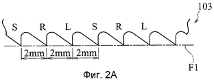
Как показано на фиг.2А и 2В, применяемый в настоящее время способ для решения этой проблемы заключается просто в использовании для разрезания трубы W ножовочного полотна 103, имеющего меньший шаг зубьев по сравнению с толщиной стенки трубы W. На фиг.5 показаны условия, при которых разрезают трубу W, имеющую диаметр 50 мм и толщину стенки 3 мм, используя ножовочное полотно 103 (ножовочное полотно, показанное на фигурах 2А и 2В), имеющее шаг зубьев 2 мм.As shown in FIGS. 2A and 2B, the current method for solving this problem is simply to use a
Поскольку шаг 2 мм зубьев ножовочного полотна 103 является небольшим по отношению к толщине 3 мм стенки трубы W, то при соблюдении этих условий, даже если ножовочное полотно 103 подходит близко к центру трубы, заготовка W не входит между вершинами ножовочного полотна 103, и не происходит мгновенного свободного опускания ножовочного полотна, вследствие чего процесс резания осуществляется соответствующим образом.Since the 2 mm pitch of the teeth of the
Когда разрезают сплошной материал W (заготовку, показанную на фиг.3), имеющий диаметр 50 мм, используя то же самое ножовочное полотно 103, а именно ножовочное полотно 103 (ножовочное полотно, показанное на фиг.2А и 2В), имеющее шаг зубьев 2 мм, то мгновенного свободного опускания ножовочного полотна не будет, и чрезмерная нагрузка при резании не возникает, поскольку шаг зубьев ножовочного полотна достаточно небольшой по сравнению с диаметром заготовки W. Однако количество зубьев ножовочного полотна 103, действующих на длине резания заготовки W, большое, и при резании нагрузка на каждый зуб, обусловленная заготовкой W, становится небольшой. Поэтому возникает проблема, заключающаяся в том, что продолжительность резания становится значительной по сравнению со случаем, когда сплошной материал W разрезают посредством ножовочного полотна 101, имеющего шаг зубьев 4 мм.When a solid material W (preform shown in FIG. 3) having a diameter of 50 mm is cut using the
По описанной выше причине при разрезании заготовки, такой как сплошной материал и труба, возникает проблема, которая заключается в необходимости перестановки ножовочного полотна, чтобы оно имело необходимый шаг зубьев, соответствующий форме и размеру заготовки W, а для перестановки ножовочных полотен необходимы время и рабочая сила.For the reason described above, when cutting a workpiece, such as a solid material and a pipe, a problem arises that consists in the need to rearrange the hacksaw blade so that it has the necessary tooth pitch corresponding to the shape and size of the workpiece W, and time and labor are required to rearrange the hacksaw blades .
На строительных площадках и в аналогичных местах нарезают разнообразные заготовки, и поэтому нельзя пренебрегать затратами труда на перестановку ножовочных полотен, имеющих разные шаги зубьев в соответствии с формой и размером заготовок. Если же ради предотвращения поломки зубьев заранее установить ножовочное полотно, имеющее относительно небольшой шаг зубьев, то в случае, когда заготовка имеет относительно большую длину резания, возникает проблема, которой нельзя пренебречь, поскольку продолжительность резания становится значительной.A variety of workpieces are cut at construction sites and similar places, and therefore, labor costs for rearranging hacksaw blades having different tooth steps in accordance with the shape and size of the workpieces cannot be neglected. If, in order to prevent tooth breakage, a hacksaw blade having a relatively small tooth pitch is installed in advance, then in the case when the workpiece has a relatively large cutting length, a problem arises that cannot be neglected, since the cutting time becomes significant.
Изобретение направлено на решение указанных выше проблем, и целью изобретения является создание ножовочного полотна, обеспечивающего возможность эффективного разрезания заготовок, имеющих относительно большую или небольшую длину резания, при этом предотвращается возможность поломки зубьев.The invention is aimed at solving the above problems, and the aim of the invention is to create a hacksaw blade that enables efficient cutting of workpieces having a relatively large or short cutting length, while preventing the possibility of tooth breakage.
Раскрытие изобретенияDisclosure of invention
Для решения указанной цели в соответствии с первым аспектом изобретения разработано ножовочное полотно со схемой развода, содержащей комбинацию первой группы зубьев, имеющей зуб без развода и отогнутые вбок зубья с разводом влево и вправо, и второй группы зубьев, имеющей отогнутые вбок зубья с разводом влево и вправо, причем схема развода выполнена повторяющейся соответствующим образом, при этом степень развода зубьев с разводом влево и вправо из второй группы зубьев меньше или равна степени развода зубьев с разводом влево и вправо из первой группы зубьев.To achieve this goal, in accordance with the first aspect of the invention, a hacksaw blade with a divorce pattern is developed comprising a combination of a first group of teeth having a tooth without a divorce and teeth bent to the side with a left and right bend, and a second group of teeth having a teeth bent to the side with a bend to the left and to the right, and the pattern of divorce is repeated appropriately, while the degree of divorce of teeth with a left and right apart from the second group of teeth is less than or equal to the degree of divorce of teeth with a divorce left and right from a ditch group of teeth.
В соответствии со вторым аспектом изобретения разработано ножовочное полотно со схемой развода, содержащей комбинацию первой группы зубьев, имеющей зуб без развода и отогнутые вбок зубья с разводом влево и вправо, и второй группы зубьев, имеющей отогнутые вбок зубья с разводом влево и вправо, причем схема развода выполнена повторяющейся соответствующим образом, а высота зубьев из второй группы зубьев меньше высоты зубьев из первой группы зубьев.In accordance with a second aspect of the invention, a hacksaw blade is provided with a divorce pattern comprising a combination of a first group of teeth having a tooth without a divorce and teeth bent sideways left and right, and a second group of teeth having a teeth bent sideways bent left and right, wherein the divorce is performed appropriately and the height of the teeth from the second group of teeth is less than the height of the teeth from the first group of teeth.
В соответствии с третьим аспектом изобретения в ножовочном полотне из второго аспекта степень развода зубьев пилы с разводом влево и вправо из второй группы зубьев меньше или равна степени развода зубьев пилы с разводом влево и вправо из первой группы зубьев.In accordance with a third aspect of the invention, in a hacksaw blade from the second aspect, the degree of divorce of the teeth of the saw with a left and right bite from the second group of teeth is less than or equal to the degree of divorce of the teeth of the saw with a bend left and right from the first group of teeth.
В соответствии с четвертым аспектом изобретения разработано ножовочное полотно со схемой развода, содержащей комбинацию первой и второй групп зубьев, каждая из которых имеет по меньшей мере зуб без развода и пару отогнутых вбок зубьев с разводом влево и вправо, причем схема развода выполнена повторяющейся соответствующим образом, при этом высота зубьев пилы из второй группы зубьев меньше высоты зубьев пилы из первой группы зубьев, шаг вершин вместе со впадинами зубьев пилы из второй группы зубьев меньше шага вершин вместе со впадинами зубьев пилы из первой группы зубьев, степень развода зубьев с разводом влево и вправо из второй группы зубьев равна или меньше степени развода зубьев с разводом влево и вправо из первой группы зубьев.In accordance with a fourth aspect of the invention, a hacksaw blade is provided with a divorce pattern comprising a combination of the first and second groups of teeth, each of which has at least a tooth without a divorce and a pair of teeth bent sideways with a left and right bend, and the divorce pattern is made in a corresponding manner, the height of the teeth of the saw from the second group of teeth is less than the height of the teeth of the saw from the first group of teeth, the pitch of the vertices together with the depressions of the teeth of the saw from the second group of teeth is less than the pitch of the vertices together with the depressions bev saw teeth of the first group, the degree divorce set teeth left and right of the second teeth group are equal to or less than the degree divorce set teeth left and right of the first teeth group.
В соответствии с пятым аспектом изобретения разработано ножовочное полотно со схемой развода, содержащей комбинацию первой группы зубьев, имеющей по меньшей мере зуб без развода и пару отогнутых вбок зубьев с разводом влево и вправо, и второй группы зубьев, имеющей по меньшей мере пару зубьев с разводом влево и вправо, причем схема развода выполнена повторяющейся соответствующим образом, при этом высота зубьев пилы из второй группы зубьев меньше высоты зубьев пилы из первой группы зубьев, шаг вершин вместе со впадинами зубьев пилы из второй группы зубьев меньше шага вершин вместе со впадинами зубьев пилы из первой группы зубьев, степень развода зубьев с разводом влево и вправо из второй группы зубьев равна или меньше степени развода зубьев с разводом влево и вправо из первой группы зубьев.In accordance with a fifth aspect of the invention, a hacksaw blade is provided with a divorce pattern comprising a combination of a first group of teeth having at least a tooth without a divorce and a pair of teeth bent sideways left and right and a second group of teeth having at least a pair of teeth with a divorce left and right, and the divorce scheme is made repeating accordingly, while the height of the teeth of the saw from the second group of teeth is less than the height of the teeth of the saw from the first group of teeth, the step of the vertices together with the hollows of the teeth of the saw from the second of the tooth group is less than the step of the vertices together with the tooth troughs of the saw from the first group of teeth, the degree of tooth bite with a left and right bite from the second group of teeth is equal to or less than the degree of tooth bite with a left and right bite from the first group of teeth.
В соответствии с шестым аспектом в ножовочном полотне по любому одному из аспектов с первого по пятый вторая группа зубьев включает зуб без развода, при этом количество зубьев первой группы зубьев и количество зубьев второй группы зубьев являются одинаковыми.According to a sixth aspect, in a hacksaw blade according to any one of the first to fifth aspects, the second group of teeth includes a tooth without a divorce, wherein the number of teeth of the first group of teeth and the number of teeth of the second group of teeth are the same.
В соответствии с седьмым аспектом в ножовочном полотне по любому одному аспекту с первого по шестой количество зубьев пилы с разводом влево и вправо из первой группы зубьев и количество зубьев пилы с разводом влево и вправо из второй группы зубьев являются одинаковыми.According to a seventh aspect, in a hacksaw blade according to any one aspect from the first to the sixth, the number of saw teeth left and right in the first tooth group and the number of teeth of the saw left and right in the second tooth group are the same.
В соответствии с восьмым аспектом в ножовочном полотне по любому одному аспекту с первого по седьмой первые группы зубьев и вторые группы зубьев расположены поочередно.According to an eighth aspect, in the hacksaw blade of any one aspect, the first to seventh first tooth groups and second tooth groups are arranged alternately.
В соответствии с девятым аспектом в ножовочном полотне по любому одному из аспектов с первого по восьмой количество зубьев второй группы зубьев больше количества зубьев первой группы зубьев.According to a ninth aspect, in a hacksaw blade according to any one of the first to eighth aspects, the number of teeth of the second tooth group is greater than the number of teeth of the first tooth group.
В соответствии с десятым аспектом в ножовочном полотне по любому одному аспекту с первого по девятый количество зубьев первой группы зубьев больше количества зубьев второй группы зубьев.According to a tenth aspect, in a hacksaw blade according to any one aspect, from the first to the ninth, the number of teeth of the first tooth group is greater than the number of teeth of the second tooth group.
В соответствии с одиннадцатым аспектом в ножовочном полотне по любому одному из аспектов с первого по десятый зубья пилы из зубьев с разводом влево и вправо первой и второй групп зубьев, которые отогнуты в одном и том же направлении, расположены непрерывно.In accordance with an eleventh aspect, in a hacksaw blade according to any one of the first to tenth tooth teeth of a saw with a left and right bend of the first and second groups of teeth that are bent in the same direction, are arranged continuously.
В соответствии с двенадцатым аспектом в ножовочном полотне по любому одному из аспектов с первого по десятый зубья пилы из зубьев с разводом влево и вправо первой и второй групп зубьев, которые отогнуты в одном и том же направлении, не расположены непрерывно.According to a twelfth aspect, in a hacksaw blade according to any one of the first to tenth teeth of a saw blade made of teeth with a left and right bite of the first and second groups of teeth that are bent in the same direction, are not arranged continuously.
В соответствии с тринадцатым аспектом в ножовочном полотне по любому одному из аспектов с первого по двенадцатый шаги между зубьями не равны друг другу.According to a thirteenth aspect, in the hacksaw blade according to any one of the first to twelfth aspects, the steps between the teeth are not equal to each other.
В соответствии с четырнадцатым аспектом в ножовочном полотне по любому одному из аспектов с первого по тринадцатый неравные шаги представляют собой шаги двух видов.According to the fourteenth aspect, in a hacksaw blade according to any one of the first to thirteenth aspects, the unequal steps are two kinds of steps.
В соответствии с пятнадцатым аспектом в ножовочном полотне по любому одному из аспектов с первого по четырнадцатый разность высот между зубьями из первой группы зубьев и зубьями из второй группы зубьев равна 0,2 мм или меньше.According to a fifteenth aspect, in a hacksaw blade according to any one of the first to fourteenth aspects, the height difference between the teeth from the first tooth group and the teeth from the second tooth group is 0.2 mm or less.
В соответствии с шестнадцатым аспектом в ножовочном полотне по любому одному из аспектов с первого по пятнадцатый дно впадины зуба пилы из первой группы зубьев находится ближе к вершине, чем впадины зуба пилы из первой группы зубьев.According to a sixteenth aspect, in a hacksaw blade according to any one of the first to fifteenth aspects, the bottom of the tooth tooth cavity of the first tooth group is closer to the tip than the tooth tooth cavity of the first tooth group.
В соответствии с семнадцатым аспектом в ножовочном полотне по четвертому или пятому аспекту зуб пилы из второй группы зубьев расположен между зубьями пилы из первой группы зубьев.According to a seventeenth aspect, in a hacksaw blade according to the fourth or fifth aspect, a tooth of a saw from a second group of teeth is located between teeth of a saw from a first group of teeth.
Как описано выше, в ножовочном полотне согласно настоящему изобретению схема развода содержит комбинацию первой группы зубьев, включающей зуб без развода и зубья с разводом влево и вправо, имеющие большую высоту, и второй группы зубьев, включающей зубья с разводом влево и вправо, имеющими меньшую степень развода по сравнению со степенью развода разведенных зубьев из первой группы зубьев.As described above, in the hacksaw blade according to the present invention, the divorce pattern comprises a combination of a first group of teeth, including a tooth without a divorce, and teeth with a left and right bend, having a higher height, and a second group of teeth, including a teeth with a bend, left and right, with a lower degree divorce compared to the degree of divorce of diluted teeth from the first group of teeth.
Поэтому можно легко разрезать сплошной материал и трубу и осуществлять процесс резания без поломки зубьев, а описанные выше известные проблемы могут быть исключены.Therefore, it is possible to easily cut the solid material and the pipe and carry out the cutting process without breaking the teeth, and the known problems described above can be eliminated.
Краткое описание чертежейBrief Description of the Drawings
На чертежах:In the drawings:
фиг.1А – вид спереди, иллюстрирующий форму вершин зубьев на участке известного ножовочного полотна;figa is a front view illustrating the shape of the tops of the teeth on the site of the known hacksaw blade;
фиг.1В – вид внизу, иллюстрирующий форму вершин зубьев на участке известного ножовочного полотна по фиг.1А;figv is a bottom view illustrating the shape of the tops of the teeth on the site of the known hacksaw blade of figa;
фиг.2А – вид спереди, иллюстрирующий форму вершин зубьев на участке известного ножовочного полотна;figa is a front view illustrating the shape of the tops of the teeth on the site of the known hacksaw blade;
фиг.2В – вид снизу, иллюстрирующий форму вершин зубьев на участке известного ножовочного полотна по фиг. 2А;2B is a bottom view illustrating the shape of the tips of the teeth in a portion of the known hacksaw blade of FIG. 2A;
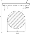
фиг.3 – вид, поясняющий условия, при которых осуществляется разрезание сплошного материала ножовочным полотном, имеющим шаг зубьев 4 мм;figure 3 is a view explaining the conditions under which the cutting of solid material with a hacksaw blade having a tooth pitch of 4 mm;
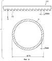
фиг.4 – вид, поясняющий условия, при которых осуществляется разрезание трубы с толщиной стенки 3 мм ножовочным полотном, имеющим шаг зубьев 4 мм;4 is a view explaining the conditions under which a pipe is cut with a wall thickness of 3 mm with a hacksaw blade having a tooth pitch of 4 mm;
фиг.5 – вид, поясняющий условия, при которых осуществляется разрезание трубы с толщиной стенки 3 мм ножовочным полотном, имеющим шаг зубьев 2 мм;5 is a view explaining the conditions under which a pipe is cut with a wall thickness of 3 mm with a hacksaw blade having a tooth pitch of 2 mm;
фиг.6А – вид спереди, иллюстрирующий форму вершин на участке ножовочного полотна согласно первому варианту осуществления настоящего изобретения;6A is a front view illustrating the shape of the peaks in a hacksaw blade portion according to a first embodiment of the present invention;
фиг.6В – вид снизу, иллюстрирующий форму вершин на участке соответствующего изобретению ножовочного полотна по фиг.6А;figv is a bottom view illustrating the shape of the peaks in the area corresponding to the invention of the hacksaw blade of figa;
фиг.6С – вид снизу, иллюстрирующий модификацию формы вершин зубьев ножовочного полотна по фиг.6В;figs is a bottom view illustrating a modification of the shape of the vertices of the teeth of the hacksaw blade of figv;
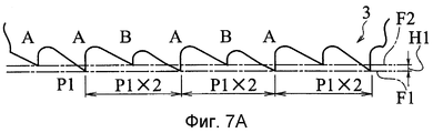
фиг.7А – вид спереди, иллюстрирующий форму вершин зубьев на участке ножовочного полотна согласно второму варианту осуществления настоящего изобретения;7A is a front view illustrating the shape of the tips of the teeth in the hacksaw blade section according to the second embodiment of the present invention;
фиг.7В – вид снизу, иллюстрирующий форму вершин зубьев на участке соответствующего изобретению ножовочного полотна по фиг.7А;figv is a bottom view illustrating the shape of the tops of the teeth in the area corresponding to the invention of the hacksaw blade of figa;
фиг.7С – вид снизу, иллюстрирующий модификацию формы вершин зубьев ножовочного полотна по фиг.7В;figs is a bottom view illustrating a modification of the shape of the vertices of the teeth of the hacksaw blade of figv;
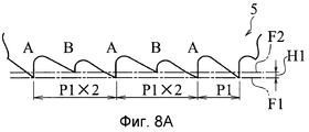
фиг.8А – вид спереди, иллюстрирующий форму вершин зубьев на участке ножовочного полотна согласно третьему варианту осуществления настоящего изобретения;figa is a front view illustrating the shape of the tops of the teeth on the site of the hacksaw blade according to the third variant of implementation of the present invention;
фиг.8В – вид снизу, иллюстрирующий форму вершин зубьев на участке соответствующего изобретению ножовочного полотна по фиг.8А;figv is a bottom view illustrating the shape of the tops of the teeth in the area corresponding to the invention of the hacksaw blade of figa;
фиг.9А – вид спереди, иллюстрирующий форму вершин зубьев на участке ножовочного полотна согласно четвертому варианту осуществления настоящего изобретения;figa is a front view illustrating the shape of the tops of the teeth on the site of the hacksaw blade according to the fourth embodiment of the present invention;
фиг.9В – вид снизу, иллюстрирующий форму вершин зубьев на участке соответствующего изобретению ножовочного полотна по фиг.9А;figv is a bottom view illustrating the shape of the tops of the teeth in the area corresponding to the invention of the hacksaw blade of figa;
фиг.10А – вид спереди, иллюстрирующий форму вершин зубьев на участке ножовочного полотна согласно пятому варианту осуществления настоящего изобретения;figa is a front view illustrating the shape of the tips of the teeth on the site of the hacksaw blade according to the fifth embodiment of the present invention;
фиг.10В – вид снизу, иллюстрирующий форму вершин зубьев на участке соответствующего изобретению ножовочного полотна по фиг.10А;figv is a bottom view illustrating the shape of the tops of the teeth in the area corresponding to the invention of the hacksaw blade of figa;
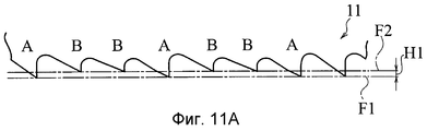
фиг.11А – вид спереди, иллюстрирующий форму вершин зубьев на участке ножовочного полотна согласно шестому варианту осуществления настоящего изобретения;11A is a front view illustrating the shape of the tops of the teeth in the hacksaw blade according to the sixth embodiment of the present invention;
фиг.11В – вид снизу, иллюстрирующий форму вершин зубьев на участке соответствующего изобретению ножовочного полотна по фиг.11А;11B is a bottom view illustrating the shape of the tips of the teeth in the area according to the invention of the hacksaw blade of FIG. 11A;
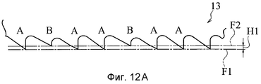
фиг.12А – вид спереди, иллюстрирующий форму вершин зубьев на участке ножовочного полотна согласно седьмому варианту осуществления настоящего изобретения;figa is a front view illustrating the shape of the tops of the teeth on the site of the hacksaw blade according to the seventh embodiment of the present invention;
фиг.12В – вид снизу, иллюстрирующий форму вершин зубьев на участке соответствующего изобретению ножовочного полотна по фиг.12А;figv is a bottom view illustrating the shape of the tops of the teeth in the area corresponding to the invention of the hacksaw blade of figa;
фиг.13А – вид спереди, иллюстрирующий форму вершин зубьев на участке ножовочного полотна согласно восьмому варианту осуществления настоящего изобретения;figa is a front view illustrating the shape of the tops of the teeth on the site of the hacksaw blade according to the eighth embodiment of the present invention;
фиг.13В – вид снизу, иллюстрирующий форму вершин зубьев на участке соответствующего изобретению ножовочного полотна по фиг.13А;figv is a bottom view illustrating the shape of the tops of the teeth in the area corresponding to the invention of the hacksaw blade of figa;
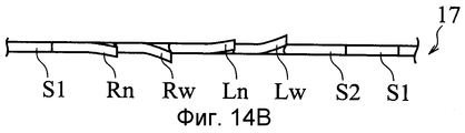
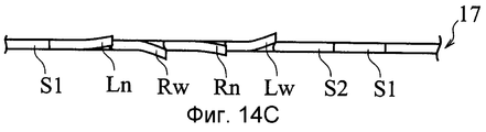
фиг.14А – вид спереди, иллюстрирующий форму вершин зубьев на участке ножовочного полотна согласно девятому варианту осуществления настоящего изобретения;figa is a front view illustrating the shape of the tops of the teeth on the site of the hacksaw blade according to the ninth embodiment of the present invention;
фиг.14В – вид снизу, иллюстрирующий форму вершин зубьев на участке соответствующего изобретению ножовочного полотна по фиг.14А;figv is a bottom view illustrating the shape of the tops of the teeth in the area corresponding to the invention of the hacksaw blade of figa;
фиг.14С – вид снизу, иллюстрирующий модификацию формы вершин зубьев ножовочного полотна по фиг.14В;figs is a bottom view illustrating a modification of the shape of the vertices of the teeth of the hacksaw blade of figv;
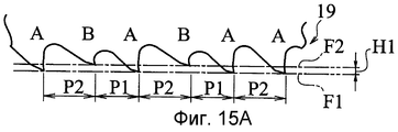
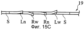
фиг.15А – вид спереди, иллюстрирующий форму вершин зубьев на участке ножовочного полотна согласно десятому варианту осуществления настоящего изобретения;figa is a front view illustrating the shape of the tops of the teeth on the site of the hacksaw blade according to the tenth embodiment of the present invention;
фиг.15В – вид снизу, иллюстрирующий форму вершин зубьев на участке соответствующего изобретению ножовочного полотна по фиг.15А; иfigv is a bottom view illustrating the shape of the tops of the teeth in the area corresponding to the invention of the hacksaw blade of figa; and
фиг.15С – вид снизу, иллюстрирующий модификацию формы вершин ножовочного полотна по фиг.15В.figs is a bottom view illustrating a modification of the shape of the vertices of the hacksaw blade of figv.
Лучшие варианты осуществления изобретенияThe best embodiments of the invention
Варианты осуществления настоящего изобретения будут пояснены с использованием чертежей. Ножовочным полотном согласно вариантам осуществления изобретения разрезают заготовки путем перемещения ножовочного полотна, изображенного на чертежах, вправо.Embodiments of the present invention will be explained using the drawings. The hacksaw blade according to the embodiments of the invention is cut into blanks by moving the hacksaw blade shown in the drawings to the right.
Обратимся к фиг.6А и 6В, на которых в ножовочном полотне 1 согласно первому варианту осуществления настоящего изобретения схема развода, включающая комбинацию первой группы зубьев (зубья пилы, принадлежащие к первой группе зубьев, показаны символами А) и второй группы зубьев (зубья пилы, принадлежащие ко второй группе зубьев, показаны символами В), выполнена повторяющейся соответствующим образом. Первая группа зубьев имеет зуб S без развода, который не отогнут в поперечном направлении (в направлении толщины ножовочного полотна 1) по отношению к ножовочному полотну 1, и пару зубьев Lw и Rw с разводом влево и вправо, имеющих относительно большую степень развода в поперечном направлении (то есть ширина развода является большой). Вторая группа зубьев имеет пару зубьев Ln и Rn с разводом вправо и влево, имеющих меньшую степень развода (то есть ширина развода является небольшой) по сравнению со степенью развода зубьев Lw и Rw с разводом влево и вправо из первой группы А зубьев.Referring to FIGS. 6A and 6B, in a
Для разрезания заготовки W ножовочное полотно 1, показанное на чертежах, продвигают слева направо. В этом случае в процессе резания зубья Lw, Ln, Rw, Rn, S и S упирают в заготовку W для того, чтобы происходил процесс резания.To cut the workpiece W, the
В ножовочном полотне 1, показанном на фиг.6А и 6В, первая группа А зубьев содержит четыре зуба, а именно два зуба S без развода и пару зубов Lw и Rw с разводом влево и вправо, имеющих относительно большую степень развода. Вторая группа В содержит два зуба, а именно пару зубьев Ln и Rn с разводом влево и вправо, имеющих меньшую степень развода по сравнению со степенью развода зубьев Lw и Rw с разводом влево и вправо из первой группы А зубьев. Первую группу А зубьев и вторую группу В зубьев комбинируют с целью образования схемы развода. Шаги Р1 вершин зубьев делают одинаковыми и задают, например, равными 2 мм.In the
Когда заготовку W, такую как сплошной материал, показанный на фиг.3, имеющую относительно большую длину резания, разрезают, используя ножовочное полотно 1, имеющее указанную выше конструкцию, то, поскольку степень развода зубьев Ln и Rn с разводом влево и вправо из второй группы В зубьев меньше по сравнению со степенью развода зубьев Lw и Rw с разводом влево и вправо из первой группы А зубьев, сила, способствующая процессу резания при разрезании заготовки W, необходимая для расширения канавки для прохода режущего инструмента, является небольшой. Поскольку сила небольшая, соответственно становится большим шаг зубьев ножовочного полотна. То есть, если не учитывать вторую группу В зубьев, обеспечивающую меньшую силу, способствующую процессу резания, то расстояние между разведенными зубьями, которое в значительной степени содействует процессу резания, представляет собой расстояние между разведенным влево зубом Lw и разведенным вправо зубом Rw, а также между разведенным вправо зубом Rw и зубом S без развода из первой группы А зубьев, посредством которой в основном осуществляется процесс резания. Это выглядит так, как если бы ножовочным полотном, имеющим большой шаг (Р1×2) зубьев, разрезали заготовку W. Расстояние между зубьями S и S без развода является исходным шагом Р1.When a workpiece W, such as the solid material shown in FIG. 3, having a relatively long cutting length, is cut using a
Поэтому, когда сплошной материал, показанный на фиг.3, разрезали, используя ножовочное полотно 1 настоящего изобретения и известное ножовочное полотно 103, показанное на фиг.2А и 2В, то при одинаковых условиях резания, таких как рабочие скорости ленточно-отрезного станка и ножовочного полотна, а также нагрузки при резании, сравнение результатов показало, что продолжительность резания ножовочным полотном 1 настоящего изобретения была меньшей.Therefore, when the solid material shown in FIG. 3 was cut using the
Во время указанного выше процесса резания, когда заготовку W разрезали посредством ножовочного полотна 1 с шагом (Р1×2) зубьев пилы и с шагом Р1, резонанс ножовочного полотна во время процесса резания был ограниченным и шумы были ограниченными. Поскольку зубья с разводом влево и вправо выполнены равновеликими по отношению друг к другу, составляющие силы, действующие на ножовочное полотно в поперечном направлении, компенсировались.During the above cutting process, when the workpiece W was cut with a
Когда разрезали сплошной материал, продолжительность резания была меньше, чем для известного ножовочного полотна 103, показанного на фиг.2А и 2В, а при сравнении продолжительности резания, в том числе для известного ножовочного полотна 101, показанного на фиг.1А и 1В, результаты оказались такими, что продолжительность резания для ножовочного полотна 101 меньше, чем продолжительность резания для ножовочного полотна 1, которая меньше, чем продолжительность резания для ножовочного полотна 103.When the solid material was cut, the cutting time was shorter than for the known
Если, используя ножовочное полотно 1, показанное на фиг.6А и 6В, разрезать такую заготовку W, как трубу, показанную на фиг.5, то шаг Р1 зубьев ножовочного полотна, составляющий 2 мм, меньше толщины 3 мм стенки трубы, и даже если ножовочное полотно 1 достигнет почти центра трубы, заготовка W не войдет между вершинами зубьев ножовочного полотна, не произойдет мгновенного свободного опускания ножовочного полотна, и заготовка W будет соответствующим образом разрезана без поломки зубьев.If, using a
То есть во время разрезания заготовки в случае, когда сопротивление резанию большое, а скорость резания относительно небольшая, аналогично случаю разрезания сплошного материала, в основном режут зубья пилы из первой группы А зубьев. Когда сопротивление резанию относительно небольшое, а скорость резания относительно большая, аналогично случаю разрезания трубы, совместно режут как зубья первой группы, так и зубья второй группы, и без поломки зубьев можно эффективно разрезать как заготовку, имеющую относительно большую длину резания, так и заготовку, имеющую небольшую длину резания. В результате можно исключить работу по перестановке ножовочных полотен в зависимости от заготовок, и также можно уменьшить количество требуемых ножовочных полотен.That is, during cutting of the workpiece in the case when the cutting resistance is large and the cutting speed is relatively small, similar to the case of cutting solid material, mainly saw teeth from the first group A of teeth are cut. When the cutting resistance is relatively small and the cutting speed is relatively large, similar to the case of cutting the pipe, both the teeth of the first group and the teeth of the second group are cut together, and without breaking the teeth, it is possible to effectively cut both a workpiece having a relatively long cutting length and a workpiece, having a short cutting length. As a result, it is possible to exclude the work of rearranging hacksaw blades depending on the workpieces, and it is also possible to reduce the number of hacksaw blades required.
Как показано на фиг.6С, допустимо, чтобы степень развода зубьев Lw и Rw с разводом влево и вправо из первой группы А зубьев и степень развода разведенных зубьев Ln и Rn из второй группы В зубьев была по существу одинаковой. В этом случае может проявляться описанный выше эффект, и поскольку разведенные зубья Ln и Rn из второй группы В зубьев вносят небольшой вклад в процесс резания, отрезанная часть заготовки W оказывается зачищенной, и качество отрезанной части заготовки дополнительно повышается.As shown in FIG. 6C, it is acceptable that the degree of divorce of the teeth Lw and Rw left and right from the first group A of teeth and the degree of divorce of the diluted teeth Ln and Rn of the second group B of teeth is substantially the same. In this case, the effect described above may occur, and since the split teeth Ln and Rn from the second tooth group B make a small contribution to the cutting process, the cut part of the workpiece W is trimmed, and the quality of the cut part of the workpiece is further improved.
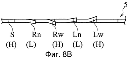
На фиг.7А и 7В показано ножовочное полотно 3 второго варианта осуществления изобретения. В ножовочном полотне 3 имеется разность Н1 высот между зубьями пилы, соответствующими первой группе А зубьев, и зубьями пилы, соответствующими второй группе В зубьев, при этом расстояние между зубьями пилы равно шагу Р1 зубьев.7A and 7B show a
Другими словами, вершины зубьев S без развода, а также зубьев Lw и Rw расположены так, что они совпадают с первой воображаемой линией F1, показанной в виде штрихпунктирной линии. С другой стороны, вершины зубьев St, Ln и Rn пилы расположены так, что они совпадают со второй воображаемой линией F2, показанной в виде штрихпунктирной линии. Разность высот между первой воображаемой линией F1 и второй воображаемой линией F2 соответствует разности Н1 высот зубьев пилы.In other words, the vertices of the teeth S without a divorce, as well as the teeth Lw and Rw are arranged so that they coincide with the first imaginary line F1, shown as a dash-dot line. On the other hand, the vertices of the saw teeth St, Ln and Rn are arranged so that they coincide with the second imaginary line F2, shown as a dash-dot line. The height difference between the first imaginary line F1 and the second imaginary line F2 corresponds to the difference H1 of the heights of the saw teeth.
Поскольку имеется разность Н1 высот между вершинами совокупности зубьев S, Lw и Rw и вершинами зубьев St, Ln и Rn пилы, то вследствие этого глубины впадин являются различными. А именно разведенные зубья Ln и Rn, принадлежащие ко второй группе В зубьев, имеют небольшие высоты (что показано с помощью (L)), а передняя впадина (на правой стороне чертежей и выше по ходу движения относительно направления перемещения ножовочного полотна) является более мелкой по сравнению со впадиной перед зубьями St, Lw, Rw пилы, принадлежащими к первой группе А зубьев. Таким образом, делая высоту зуба более низкой, а переднюю впадину более мелкой, можно повысить жесткость зуба пилы, принадлежащего ко второй группе В зубьев, ограничить изгиб зуба пилы в направлении развода под действием силы резания, когда заготовка отрезается зубом пилы, и повысить режущую способность.Since there is a height difference H1 between the vertices of the set of teeth S, Lw and Rw and the vertices of the teeth St, Ln and Rn of the saw, the depths of the depressions are therefore different. Namely, the diluted teeth Ln and Rn belonging to the second group of teeth B have small heights (as shown by (L)), and the front cavity (on the right side of the drawings and higher along the direction of movement of the hacksaw blade) is smaller compared with the cavity in front of the teeth St, Lw, Rw saws belonging to the first group And teeth. Thus, by making the tooth height lower and the front cavity smaller, it is possible to increase the stiffness of the tooth of the saw belonging to the second group B of teeth, to limit the bending of the tooth of the saw in the direction of divorce under the action of the cutting force when the workpiece is cut off by the saw tooth, and to increase the cutting ability .
Что касается разности высот между зубьями с разводом влево и вправо из первой группы А зубьев и зубьями с разводом влево и вправо из второй группы В зубьев, то высота зуба с разводом, имеющего небольшую степень развода, из второй группы В зубьев является наименьшей. Другими словами, зуб с разводом, имеющий небольшую высоту, имеет меньшую степень развода по сравнению с зубом с разводом, имеющим большую высоту.As for the height difference between the teeth left and right in the first group A of teeth and the teeth left and right in the second tooth group B, the height of the tooth with a divorce having a small degree of divorce from the second tooth group B is the smallest. In other words, a tooth with a divorce having a small height has a lower degree of divorce than a tooth with a divorce having a high height.
Более конкретно, первая группа А зубьев содержит в сумме три зуба, то есть один зуб S без развода, имеющий большую высоту (что показано с помощью (Н)), и пару зубьев Lw и Rw с разводом влево и вправо, имеющих относительно большую степень развода и имеющих большую высоту (что показано с помощью (Н)). Вторая группа В зубьев содержит в сумме три зуба, то есть один зуб S без развода, имеющий меньшую высоту по сравнению с высотой зуба S без развода из первой группы А, и пару разведенных зубьев Ln и Rn, имеющих меньшую высоту и меньшую степень развода по сравнению с высотой и степенью развода зубьев Lw и Rw с разводом влево и вправо из первой группы А зубьев. Количество разведенных зубьев, а также количество зубьев с разводом влево и вправо являются одинаковым, и одна схема развода образуется в сумме шестью зубьями пилы из первой группы А зубьев и из второй группы В зубьев. Зубья пилы из первой группы А зубьев и зубья пилы из второй группы В зубьев расположены поочередно.More specifically, the first group A of teeth contains a total of three teeth, that is, one tooth S without a divorce, having a large height (as shown by (H)), and a pair of teeth Lw and Rw with a left and right bend, having a relatively large degree divorce and having a high height (as shown by (H)). The second tooth group B contains three teeth in total, that is, one tooth S without a divorce, having a lower height compared to the height of tooth S without a divorce from the first group A, and a pair of diluted teeth Ln and Rn having a lower height and a lower degree of divorce compared with the height and degree of divorce of the teeth Lw and Rw with a bite to the left and right of the first group A of the teeth. The number of divorced teeth, as well as the number of teeth with a left and right bend, are the same, and one divorce pattern is formed by a total of six saw teeth from the first group A of teeth and from the second group B of teeth. The teeth of the saw from the first group A of teeth and the teeth of the saw from the second group B of teeth are arranged alternately.
В ножовочном полотне 3 разность Н1 высот между вершинами зубьев пилы из первой группы А зубьев и зубьев пилы из второй группы В зубьев задают такой, что, когда длина резания большая и сопротивление резанию в направлении резанию большое, а скорость резания является относительно небольшой, как в случае разрезания сплошного материала, показанного на фиг.3, процесс резания в основном осуществляется зубьями пилы из первой группы А зубьев, а когда сопротивление резанию в направлении резанию небольшое и скорость резания является относительно высокой, как в случае разрезания трубы, показанной на фиг.5, процесс резания осуществляется посредством как первой группы А зубьев, так и второй группы В зубьев.In the
С учетом различных экспериментальных исследований предпочтительно, чтобы разность Н1 высот составляла приблизительно 0,2 мм или меньше, хотя она зависит от шага разведенных зубьев, формы, размера и вида заготовки W, и при резании металла удовлетворяющее требованиям преимущественное значение разности Н1 высот составляет 0,1 мм или меньше.Taking into account various experimental studies, it is preferable that the height difference H1 is approximately 0.2 mm or less, although it depends on the pitch of the split teeth, the shape, size and type of the workpiece W, and when cutting metal, the advantageous value of the height difference H1 is 0, 1 mm or less.
Поскольку в ножовочном полотне 1 из первого варианта осуществления изобретения зубья пилы, имеющие небольшую степень развода и зубья пилы, имеющие большую степень развода, имеют по существу одинаковые высоты зубьев, и хотя зубья пилы, имеющие небольшую степень развода, работают меньше, чем зубья пилы, имеющие большую степень развода, первые зубья пилы всегда осуществляют процесс резания в направлении резания. Тогда как в ножовочном полотне 3 из второго варианта осуществления изобретения при резании сплошного материала зубья Ln, Rn и St пилы из второй группы В зубьев почти совсем не участвуют в процессе резания в направлении резания, а больше всего процесс резания осуществляют зубья пилы из первой группы А зубьев. Следовательно, если обращать внимание только на зубья пилы из первой группы А зубьев, которые осуществляют процесс резания, то шаг зубьев будет Р1×Р2, и это выглядит так, как если бы ножовочное полотно было таким же, как известное ножовочное полотно 101, показанное на фиг.1А и 1В.Since in the
Поэтому, если условия резания, такие как рабочая скорость и нагрузка ленточно-отрезного станка и ножовочного полотна при резании, соответствуют тем же самым условиям, как в процессе резания посредством ножовочного полотна 1 из первого варианта осуществления изобретения, и если сплошной материал разрезают, используя ножовочное полотно 3 из второго варианта осуществления изобретения, и сравнивают продолжительность резания, то в результате продолжительность резания ножовочным полотном 101 примерно равна продолжительности резания ножовочным полотном 3, которая меньше продолжительности резания ножовочным полотном 1, которая, в свою очередь, меньше продолжительности резания ножовочным полотном 103. То есть по сравнению с известным ножовочным полотном 103, показанным на фиг.2А и 2В, и ножовочным полотном 1 из первого варианта осуществления изобретения, показанным на фиг.6А, 6В и 6С, продолжительность резания сплошного материала уменьшается при использовании второго варианта осуществления и почти такая же, как продолжительность резания известным ножовочным полотном 101, показанным на фиг.1А и 1В.Therefore, if the cutting conditions, such as the operating speed and the load of the band saw and the hacksaw blade during cutting, correspond to the same conditions as during the cutting process using the
С другой стороны, если заготовку W, например трубу, показанную на фиг.5, разрезают, используя ножовочное полотно 3, показанное на фиг.7А, 7В и 7С, то, когда шаг Р1 зубьев ножовочного полотна, равный 2 мм, меньше по сравнению с толщиной 3 мм стенки трубы, а сопротивление резанию в направлении резания небольшое, и существует тенденция повышения степени резания тогда, когда ножовочное полотно 3 почти достигает центра трубы, зубья пилы из второй группы В зубьев также осуществляют процесс резания, заготовка W не входит между вершинами зубьев ножовочного полотна 3, и мгновенного свободного опускания ножовочного полотна не происходит. Следовательно, процесс резания осуществляется соответствующим образом без поломки зубьев.On the other hand, if the workpiece W, for example the pipe shown in FIG. 5, is cut using a
Как показано на фиг.7С, в ножовочном полотне 3 можно одинаковым образом задать степень развода зубьев пилы из первой группы А зубьев и зубьев пилы из второй группы В зубьев. В этом случае качество резания отрезанной части заготовки повышается за счет эффекта зачистки.As shown in FIG. 7C, in the
На фиг.8А и 8В показано ножовочное полотно 5 из третьего варианта осуществления изобретения. Ножовочное полотно 5 эквивалентно ножовочному полотну 3 из второго варианта осуществления изобретения, показанному на фиг.7А, 7В и 7С, из которого удален зуб St без развода из второй группы В зубьев, и при этом шаги Р1 между зубьями пилы равны друг другу.On figa and 8B shows the
Более конкретно, первая группа А зубьев содержит в сумме три зуба, то есть один зуб S без развода, имеющий большую высоту, и пару зубьев Lw и Rw с разводом влево и вправо, имеющих относительно большую степень развода. Вторая группа В зубьев содержит в сумме два зуба, то есть пару зубьев Ln и Rn с разводом влево и вправо, имеющих меньшую высоту по сравнению с высотой зубьев Lw и Rw с разводом влево и вправо из первой группы А зубьев, и имеющих меньшую степень развода по сравнению со степенью развода разведенных зубьев Lw и Rw из первой группы зубьев. Одну схему развода образуют в сумме пять зубьев пилы из комбинации зубьев пилы из первой группы А зубьев и зубьев пилы из второй группы В зубьев.More specifically, the first group A of teeth contains a total of three teeth, that is, one tooth S without a divorce, having a large height, and a pair of teeth Lw and Rw with a bite left and right, having a relatively large degree of divorce. The second group of teeth B contains two teeth in total, that is, a pair of teeth Ln and Rn with a left and right bite, having a lower height compared to the height of the teeth Lw and Rw with a left and right bite from the first group A of teeth, and having a lower degree of divorce compared with the degree of divorce of the diluted teeth Lw and Rw from the first group of teeth. One divorce pattern is formed by a total of five saw teeth from a combination of saw teeth from the first group A of teeth and saw teeth from the second group B of teeth.
Поскольку разность Н1 высот между вершинами зубьев пилы из первой группы А зубьев и зубьев пилы из второй группы В зубьев такая же, как и в ножовочном полотне 3 из второго варианта осуществления изобретения, то пояснение этого обстоятельства опущено.Since the height difference H1 between the tops of the teeth of the saw from the first group A of teeth and the teeth of the saw from the second group B of teeth is the same as in the
В случае разрезания сплошного материала в ножовочном полотне 5 из третьего варианта осуществления изобретения, как и в ножовочном полотне 3 из второго варианта осуществления изобретения, разведенные зубья Ln и Rn из второй группы В зубьев почти совсем не участвуют в процессе резания, а зубья пилы, принадлежащие к первой группе А зубьев, осуществляют процесс резания. Если обращать внимание только на зубья пилы из первой группы А зубьев, которые осуществляют процесс резания, то, хотя средний шаг зубьев пилы в схеме развода ножовочного полотна 3 из второго варианта осуществления изобретения равен 4 мм, средний шаг зубьев пилы в схеме развода ножовочного полотна 5 из третьего варианта осуществления изобретения несколько меньше, поскольку равен приблизительно 3,3 мм [=(2+4+4)/3].In the case of cutting solid material in the
Поэтому, если условия резания, такие как рабочая скорость и нагрузка ленточно-отрезного станка и ножовочного полотна при резании, соответствуют тем же самым условиям, как в процессе резания посредством ножовочных полотен из первого и второго вариантов осуществления изобретения, и если сплошной материал разрезают, используя ножовочное полотно 5 из третьего варианта осуществления изобретения, и сравнивают продолжительность резания, то результаты оказываются такими, что продолжительность резания ножовочным полотном 101 примерно равна продолжительности резания ножовочным полотном 3, которая меньше продолжительности резания ножовочным полотном 5, которая, в свою очередь, меньше продолжительности резания ножовочным полотном 1, которая меньше продолжительности резания ножовочным полотном 103. То есть, хотя продолжительность резания сплошного материала увеличивается по сравнению со случаем использования ножовочного полотна 3 на значение величины, получаемой путем вычитания значения среднего шага первой группы А зубьев, составляющего приблизительно 3,3 мм, из значения шага, равного 4 мм, известного ножовочного полотна 101, показанного на фиг.1А и 1В, но продолжительность резания уменьшается по сравнению с известным ножовочным полотном 103, показанным на фиг.2А и 2В, и ножовочным полотном 1 из первого варианта осуществления изобретения, показанным на фиг.6А, 6В и 6С.Therefore, if the cutting conditions, such as the operating speed and load of the band saw and the hacksaw blade during cutting, correspond to the same conditions as during the cutting process using hacksaw blades from the first and second embodiments of the invention, and if the solid material is cut using
Например, когда разрезают такую заготовку W, как трубу, показанную на фиг.5, используя ножовочное полотно 5, показанное на фиг.8А и 8В, проявляется тот же самый эффект, как и в случае ножовочного полотна 3 из второго варианта осуществления изобретения, и процесс резания протекает соответствующим образом без поломки зубьев.For example, when a blank W such as the pipe shown in FIG. 5 is cut using the
На фиг.9А и 9В показано ножовочное полотно 7 в соответствии с четвертым вариантом осуществления изобретения. В этом ножовочном полотне 7 степень развода зубьев Lw и Rw с разводом влево и вправо из первой группы А зубьев и степень развода зубьев Ln и Rn с разводом влево и вправо из второй группы В зубьев по существу такая же, как в третьем варианте осуществления, показанном на фиг.8А и 8В, а шаги Р1 между зубьями пилы равны друг другу.On figa and 9B shows a
Более конкретно, первая группа А зубьев содержит в сумме три зуба, а именно, один зуб S без развода, имеющий большую высоту, и пару зубьев Lw и Rw с разводом влево и вправо, имеющих относительно большую степень развода и большую высоту. Вторая группа В зубьев содержит в сумме два зуба, а именно пару зубьев Ln и Rn с разводом влево и вправо, имеющих меньшую высоту по сравнению с высотой зубьев Lw и Rw с разводом влево и вправо из первой группы А зубьев и имеющих степень развода, которая по существу равна степени развода разведенных зубьев Lw и Rw из первой группы А зубьев. В сумме пять зубьев пилы комбинации зубьев пилы из первой группы А зубьев и зубьев пилы из второй группы В зубьев образуют одну схему развода.More specifically, the first group A of teeth contains a total of three teeth, namely, one tooth S without a divorce, having a large height, and a pair of teeth Lw and Rw with a bite left and right, having a relatively large degree of divorce and a large height. The second group of teeth B contains a total of two teeth, namely a pair of teeth Ln and Rn with a left and right bite, having a lower height compared to the height of the teeth Lw and Rw with a left and right bite from the first group A of teeth and having a degree of divorce, which essentially equal to the degree of divorce of the diluted teeth Lw and Rw from the first tooth group A. In total, five saw teeth of a combination of saw teeth from the first group A of teeth and saw teeth from the second group of teeth form one divorce pattern.
Когда сопротивление резанию большое, а скорость резания относительно небольшая, как в случае резания сплошного материала, показанного на фиг.3, в ножовочном полотне 7 описанной выше конструкции разведенные зубья Ln и Rn, имеющие небольшую высоту, из второй группы В зубьев почти совсем не участвуют в процессе резания, за исключением того, что в небольшой степени принимают участие в процессе резания, вычищая боковую поверхность канавки, которая вырезается разведенными зубьями Lw и Rw, имеющими высоту первой группы А зубьев, и при этом качество поверхности резания повышается за счет эффекта зачистки. Поскольку разность Н1 высот между вершинами зубьев пилы из первой группы А зубьев и зубьев пилы из второй группы В зубьев такая же, как и в ножовочном полотне 3 из второго варианта осуществления изобретения, пояснение этого обстоятельства опущено.When the cutting resistance is large and the cutting speed is relatively small, as in the case of cutting the solid material shown in FIG. 3, in the
Если обращать внимание только на зубья пилы из первой группы А зубьев, которые при разрезании сплошного материала в основном осуществляют процесс резания, то в ножовочном полотне 7 из четвертого варианта осуществления изобретения, как и в ножовочном полотне 5 из третьего варианта осуществления изобретения, средний шаг зубьев пилы в схеме развода равен приблизительно 3,3 мм. Поэтому, если условия резания, такие, как рабочая скорость и нагрузка ленточно-отрезного станка и ножовочного полотна при резании соответствуют тем же самым условиям, как и в процессе резания посредством ножовочных полотен из первого, второго и третьего вариантов осуществления изобретения, то при сравнении продолжительности резания сплошного материала получают такой результат, что продолжительность резания ножовочным полотном 101 примерно равна продолжительности резания ножовочным полотном 3, которая меньше продолжительности резания ножовочным полотном 5, которая, в свою очередь, примерно равна продолжительности резания ножовочным полотном 7, которая меньше продолжительности резания ножовочным полотном 1, которая, в свою очередь, меньше продолжительности резания ножовочным полотном 103.If you pay attention only to the teeth of the saw from the first group A of teeth, which when cutting solid material mainly carry out the cutting process, then in the
То есть, хотя продолжительность резания сплошного материала увеличивается по сравнению со случаями использования известного ножовочного полотна 103, показанного на фиг.2А и 2В, и ножовочного полотна 1 из первого варианта осуществления изобретения, но продолжительно резания является по существу такой же, как и для ножовочного полотна 5 из третьего варианта осуществления изобретения, показанного на фиг.8А и 8В.That is, although the cutting time of the solid material is increased compared with the use of the known
Например, когда разрезают такую заготовку W, как трубу, показанную на фиг.5, используя ножовочное полотно 7, показанное на фиг.9А и 9В, проявляется тот же самый эффект, как и в случае ножовочного полотна 3 из второго варианта осуществления изобретения, и процесс резания осуществляется соответствующим образом без поломки зубьев.For example, when a blank W such as the pipe shown in FIG. 5 is cut using the
Что касается фиг.10А и 10В, то в ножовочном полотне 9 согласно пятому варианту осуществления настоящего изобретения по сравнению с ножовочным полотном 5 из третьего варианта осуществления изобретения, показанным на фиг.3, изменен порядок расположения зубьев Lw и Rw с разводом влево и вправо из первой группы А зубьев и зубьев Ln и Rn с разводом влево и вправо из второй группы В зубьев, а шаги Р1 между зубьями пилы равны друг другу. Поскольку ножовочное полотно 7 выполнено почти так же, как и ножовочное полотно 5 из третьего варианта осуществления изобретения, показанное на фиг.8А и 8В, подробное пояснение опущено.As for figa and 10B, in the
В ножовочном полотне 9 из пятого варианта осуществления изобретения расположение зубьев Lw и Rw с разводом влево и вправо из первой группы А зубьев и зубьев Ln и Rn с разводом влево и вправо из второй группы В зубьев может быть изменено соответствующим образом. В этом случае зубья Lw и Rw с разводом влево и вправо из первой группы А зубьев и зубья Ln и Rn с разводом влево и вправо из второй группы В зубьев располагают так, чтобы зубья пилы в одном и том же направлении не были расположены непрерывно.In the
Что касается фиг.11А и 11В, то в ножовочном полотне 11 из шестого варианта осуществления изобретения зубья Ln2 и Rn2 с разводом влево и вправо, имеющие небольшую высоту и небольшую степень развода, добавлены ко второй группе В зубьев ножовочного полотна 5 из третьего варианта осуществления изобретения, показанного на фиг. 3, увеличено число зубьев пилы, а шаги 1 между зубьями пилы равны друг другу.As for figa and 11B, in the
Более конкретно, первая группа А зубьев содержит в сумме три зуба, а именно один зуб S без развода, имеющий большую высоту, и пару зубьев Lw и Rw с разводом влево и вправо, имеющих относительно большую степень развода и большую высоту. Вторая группа В зубьев содержит в сумме четыре зуба, а именно пару зубьев Ln1 и Ln2 с разводом влево и вправо, имеющих меньшую высоту по сравнению с высотой зубьев Lw и Rw с разводом влево и вправо из первой группы А зубьев и имеющих степень развода, которая по существу равна степени развода разведенных зубьев Lw и Rw из первой группы А зубьев, и пару зубьев Rn1 и Rn2 с разводом влево и вправо. В сумме семь зубьев пилы комбинации зубьев пилы из первой группы А зубьев и зубьев пилы из второй группы В зубьев образуют одну схему развода. Поскольку разность Н1 высот между вершинами зубьев пилы из первой группы А зубьев и зубьев пилы из второй группы В зубьев такая же, как и в ножовочном полотне 3 из второго варианта осуществления изобретения, подробное пояснение этого обстоятельства опущено.More specifically, the first group A of teeth contains a total of three teeth, namely one tooth S without a divorce, having a large height, and a pair of teeth Lw and Rw with a bite to the left and to the right, having a relatively large degree of divorce and a large height. The second group of teeth B contains four teeth in total, namely a pair of teeth Ln 1 and Ln 2 with a left and right bite, having a lower height compared to the height of the teeth Lw and Rw with a left and right bend from the first group A of teeth and having a degree of divorce , which is essentially equal to the degree of divorce of the diluted teeth Lw and Rw from the first group A of teeth, and a pair of teeth Rn 1 and Rn 2 with a divorce left and right. In total, seven saw teeth of a combination of saw teeth from the first group A of teeth and saw teeth from the second group of teeth form one divorce pattern. Since the height difference H1 between the tops of the teeth of the saw from the first group A of teeth and the teeth of the saw from the second group B of teeth is the same as in the
При разрезании сплошного материала в ножовочном полотне 11 из шестого варианта осуществления изобретения, как и в ножовочном полотне 5 из третьего варианта осуществления изобретения, зубья Ln1, Ln2, Rn1, Rn2 пилы из второй группы В зубьев почти совсем не участвуют в процессе резания, а процесс резания осуществляют, главным образом, зуб S без развода и разведенные зубья Lw и Rw из первой группы А зубьев. Поэтому, если обращать внимание только на зубья Lw и Rw с разводом влево и вправо из первой группы А зубьев, то расстояние между зубьями Lw и Rw с разводом влево и вправо и расстояние между разведенным зубом Rw и зубом S без развода является большим (Р1×3=6 мм), степень резания зубьев пилы повышается, а нагрузка на каждый зуб возрастает соответственно значению увеличенного шага. Поэтому нежелательно иметь относительно большой шаг зубьев ножовочного полотна, но конструкция рассмотренного вида является эффективной для ножовочного полотна, имеющего небольшой шаг зубьев.When cutting solid material in the
Например, когда разрезают такую заготовку W, как трубу, показанную на фиг.5, используя ножовочное полотно 11, показанное на фиг.11А и 11В, проявляется тот же самый эффект, как и в случае ножовочного полотна 3 из второго варианта осуществления изобретения, и процесс резания протекает соответствующим образом без поломки зубьев.For example, when a workpiece W such as the pipe shown in FIG. 5 is cut using the
Что касается фиг.12А и 12В, то в ножовочном полотне 13 из седьмого варианта осуществления изобретения зубья Lw2 и Rw2, имеющие большую высоту и относительно большую степень развода, добавлены к первой группе А зубьев ножовочного полотна 5 из третьего варианта осуществления изобретения, показанного на фиг.8А и 8В, и увеличено число зубьев пилы, а шаги 1 между зубьями пилы равны друг другу.As for figa and 12B, in the
Более конкретно, первая группа А зубьев содержит в сумме пять зубьев, а именно один зуб S без развода, имеющий большую высоту, и две пары зубьев Lw1, Lw2, Rw1, Rw2 с разводом влево и вправо, имеющих относительно большую степень развода и большую высоту. Вторая группа В зубьев содержит в сумме два зуба, а именно пару зубьев Ln и Rn с разводом влево и вправо, имеющих меньшую высоту и меньшую степень развода, чем зубья Lw и Rw с разводом влево и вправо из первой группы А зубьев. В сумме семь зубьев пилы комбинации зубьев пилы из первой группы А и зубьев пилы из второй группы зубьев В образуют одну схему развода.More specifically, the first group A of teeth contains a total of five teeth, namely one tooth S without a divorce, having a large height, and two pairs of teeth Lw 1 , Lw 2 , Rw 1 , Rw 2 with a divorce left and right, with a relatively large degree divorce and great height. The second group of teeth B contains a total of two teeth, namely a pair of teeth Ln and Rn with a left and right bite, having a lower height and a lower degree of divorce than the teeth Lw and Rw with a left and right bend from the first group A of teeth. In total, seven saw teeth of a combination of saw teeth from the first group A and saw teeth from the second group of teeth B form one divorce pattern.
В ножовочном полотне 13 из седьмого варианта осуществления изобретения исключен недостаток, обусловленный выбором шагов зубьев Lw и Rw с разводом влево и вправо из первой группы А зубьев ножовочного полотна 11 из варианта осуществления, показанного на фиг.11А и 11В. Поскольку режущая способность по отношению к сплошному материалу и к трубе, а также разность Н1 высот между вершинами зубьев пилы из первой группы А зубьев и зубьев пилы из второй группы В зубьев такие же, как и в ножовочном полотне 5 из третьего варианта осуществления изобретения, подробное пояснение этого обстоятельства опущено. Как описано выше, соответствующим образом можно изменять вид и количество зубьев пилы из первой группы А зубьев и второй группы В зубьев.In the
Что касается фиг.13А и 13В, то в ножовочном полотне 15 из восьмого варианта осуществления изобретения картина развода комбинации зубьев Lw и Rw с разводом влево и вправо из первой группы А зубьев и зубьев Ln и Rn с разводом влево и вправо из второй группы В зубьев и разность высот зубьев такие же, как и в третьем варианте осуществления изобретения, показанном на фиг.8А и 8В, и существуют два вида шагов между зубьями пилы, а именно неравные друг другу шаги.As for figa and 13B, then in the
Поскольку шаг неравномерный, возникает новый эффект, из которого вытекает, что во время процесса резания шум может быть снижен. На фиг.13А показаны два вида шагов, Р1 и Р2, но если увеличить число видов шагов, то можно эффективно ограничить резонанс, обусловленный вибрацией во время процесса резания, и дополнительно снизить шум.Since the step is uneven, a new effect arises, from which it follows that during the cutting process, noise can be reduced. On figa shows two types of steps, P1 and P2, but if you increase the number of types of steps, you can effectively limit the resonance due to vibration during the cutting process, and further reduce noise.
Поскольку режущая способность по отношению к сплошному материалу и трубе, а также разность Н1 высот между вершинами зубьев пилы из первой группы А зубьев и зубьев пилы из второй группы В зубьев пилы такие же, как и в ножовочном полотне 5 из третьего варианта осуществления изобретения, подробное пояснение этих обстоятельств опущено.Since the cutting ability with respect to the solid material and the pipe, as well as the height difference H1 between the tops of the saw teeth from the first group A of the teeth and saw teeth from the second group B of the saw teeth are the same as in the
Что касается фиг.14А и 14В, то в ножовочном полотне 17 из девятого варианта осуществления изобретения схема развода образована в сумме шестью зубьями пилы комбинации из первой группы А зубьев, содержащей три зуба, а именно, зуб S1 без развода и зубья Lw и Rw с разводом влево и вправо, и второй группы В зубьев, содержащей три зуба, а именно зуб S2 без развода и зубья Ln и Rn с разводом влево и вправо.As for figa and 14B, then in the
Как и в предшествующих вариантах осуществления изобретения, высота зуба S2 без развода и зубьев Ln и Rn с разводом влево и вправо, принадлежащих ко второй группе В зубьев, меньше по сравнению с высотой зуба S1 без развода и разведенных зубьев Lw и Rw, принадлежащих к первой группе А зубьев, а передняя впадина мельче по сравнению с передней впадиной разведенных зубьев, принадлежащих к первой группе А зубьев. Разность Н1 высот между первой группой А зубьев и второй группой В зубьев такая же, как и разность высот в каждом ножовочном полотне. Степень развода зубьев Ln и Rn с разводом влево и вправо, принадлежащих ко второй группе В зубьев, меньше или равна степени развода зубьев Lw и Rw с разводом влево и вправо, принадлежащих к первой группе А зубьев. Зубья S1, Lw, Rw, принадлежащие к первой группе А зубьев, и зубья S2, Ln, Rn пилы, принадлежащие ко второй группе В зубьев, расположены поочередно.As in the previous embodiments, the height of the tooth S2 without a divorce and the teeth Ln and Rn with a left and right bite belonging to the second group B of teeth are smaller compared to the height of the tooth S1 without a divorce and the diluted teeth Lw and Rw belonging to the first group A of the teeth, and the front cavity is smaller compared to the front cavity of the diluted teeth belonging to the first group A of teeth. The height difference H1 between the first tooth group A and the second tooth group B is the same as the height difference in each hacksaw blade. The degree of divorce of the teeth Ln and Rn with a left and right bite belonging to the second group B of teeth is less than or equal to the degree of divorce of the teeth Lw and Rw with a bite left and right belonging to the first group A of teeth. The teeth S1, Lw, Rw belonging to the first tooth group A and the saw teeth S2, Ln, Rn belonging to the second tooth group B are arranged alternately.
В ножовочном полотне 17 шаг Р1 вершин вместе со впадинами зубьев S2, Ln, Rn пилы, принадлежащих ко второй группе В зубьев, меньше шага Р2 вершин вместе со впадинами зубьев S1, Lw, Rw, принадлежащих к первой группе А зубьев. Зубья Lw и Rw с разводом влево и вправо, принадлежащие к первой группе А зубьев, и зубья Ln и Rn с разводом влево и вправо, принадлежащие ко второй группе В зубьев, можно расположить непрерывно так, чтобы зубья пилы, которые отогнуты в одном и том же направлении и находятся рядом друг с другом, образовывали друг с другом пары, показанные на фиг. 14В, или можно расположить непрерывно так, чтобы зубья пилы, которые отогнуты в разных направлениях и находятся рядом друг с другом, образовывали друг с другом пары, показанные на фиг.14С.In the
При разрезании сплошного материала W, показанного на фиг.3, в ножовочном полотне 17 описанной выше конструкции зубья S1, Lw, Rw пилы, принадлежащие к первой группе А зубьев, вносят основной вклад в процесс резания, а когда разрезают трубу, то как зубья S1, Lw, Rw пилы, принадлежащие к первой группе А зубьев, так и зубья S2, Ln, Rn пилы, принадлежащие ко второй группе В зубьев, вносят вклад в процесс резания, и можно легко разрезать сплошной материал или трубу.When cutting the solid material W shown in FIG. 3 in a
В ножовочном полотне 19 согласно десятому варианту осуществления настоящего изобретения, показанном на фиг.15А и 15В, схема развода и зубья пилы такие же, как схема развода и зубья пилы в ножовочном полотне 15 из восьмого варианта осуществления изобретения, но задний угол вершины образован с двухступенчатой стороной для увеличения вместимости впадин с тем, чтобы они легко не забивались опилками. Кроме того, поскольку режущая способность зубьев пилы, принадлежащих ко второй группе В зубьев, меньше, чем у зубьев пилы, принадлежащих к первой группе А зубьев, то глубина передней впадины зубьев пилы, принадлежащих к первой группе А зубьев, задана меньшей по сравнению с глубиной передней впадины зубьев пилы, принадлежащих ко второй группе В зубьев, так что конструкция удовлетворяет требованиям, необходимым для функционирования зубьев пилы.In the
Зубья Lw и Rw с разводом влево и вправо, принадлежащие к первой группе А зубьев, и зубья Ln и Rn с разводом влево и вправо, принадлежащие ко второй группе В, можно расположить непрерывно так, чтобы зубья пилы, которые отогнуты в одном и том же направлении и находятся рядом друг с другом, образовывали друг с другом пары, показанные на фиг.15В, или можно расположить непрерывно так, чтобы зубья пилы, которые отогнуты в разных направлениях и находятся рядом друг с другом, образовывали друг с другом пары, показанные на фиг.15С.The teeth Lw and Rw with a left and right bend belonging to the first group A of teeth, and the teeth Ln and Rn with a left and right bend belonging to the second group B, can be positioned continuously so that the saw teeth that are bent in the same direction and are adjacent to each other, formed pairs with each other, shown in figv, or can be positioned continuously so that the saw teeth, which are bent in different directions and are next to each other, formed pairs with each other, shown in figs.
Из пояснения ножовочных полотен 17 и 19 должно быть понятно, что зубья пилы, принадлежащие к первой группе А зубьев, не ограничены конкретным видом и количеством, а зубья пилы, принадлежащие ко второй группе В зубьев, также не ограничены конкретным видом и количеством. Когда схема развода образована комбинацией зубьев пилы из первой группы А зубьев и зубьев пилы из второй группы В зубьев, то предпочтительно, чтобы число зубьев с разводом влево и число зубьев с разводом вправо, включенных в схему развода, было равно друг другу. В схеме развода шаги вершин зубьев не ограничены двумя видами, а именно Р1 и Р2, и можно сочетать другие шаги. Например, в схеме развода все шаги могут быть разными.From the explanation of the
Claims (51)
Applications Claiming Priority (2)
| Application Number | Priority Date | Filing Date | Title |
|---|---|---|---|
| JP2000359937 | 2000-11-27 | ||
| JP2000-359937 | 2000-11-27 |
Publications (2)
| Publication Number | Publication Date |
|---|---|
| RU2003119078A RU2003119078A (en) | 2005-01-10 |
| RU2248261C1 true RU2248261C1 (en) | 2005-03-20 |
Family
ID=18831616
Family Applications (1)
| Application Number | Title | Priority Date | Filing Date |
|---|---|---|---|
| RU2003119078/02A RU2248261C1 (en) | 2000-11-27 | 2001-11-22 | Hacksaw blade |
Country Status (9)
| Country | Link |
|---|---|
| US (1) | US7568416B2 (en) |
| EP (1) | EP1354655A4 (en) |
| JP (1) | JP4133325B2 (en) |
| KR (1) | KR100546021B1 (en) |
| CN (1) | CN100357052C (en) |
| AU (1) | AU2002224076A1 (en) |
| RU (1) | RU2248261C1 (en) |
| TW (1) | TW494032B (en) |
| WO (1) | WO2002042028A1 (en) |
Families Citing this family (41)
| Publication number | Priority date | Publication date | Assignee | Title |
|---|---|---|---|---|
| DE10063567A1 (en) * | 2000-12-20 | 2002-07-04 | Scintilla Ag | sawblade |
| AU2003271157A1 (en) * | 2002-10-10 | 2004-05-04 | Amada Company, Limited | Saw blade |
| EP1470884B1 (en) * | 2003-04-25 | 2007-12-19 | Kapman AB | Bandsaw blade |
| SE526794C2 (en) * | 2004-03-11 | 2005-11-08 | Kapman Ab | Wood saw blade |
| US20050211046A1 (en) * | 2004-03-26 | 2005-09-29 | Thomas Rickey J | Tooth form design for reciprocating saw blade |
| JP4102817B2 (en) * | 2004-08-19 | 2008-06-18 | 株式会社アマダ | Band saw blade |
| CA2520545C (en) * | 2004-09-22 | 2009-11-24 | Irwin Industrial Tool Company | Saw blade having increased tooth stiffness and resistance to fatigue failure |
| US7913601B2 (en) * | 2006-04-28 | 2011-03-29 | Simonds International Corporation | Enhanced performance saw blade toothform pattern |
| ATE470527T1 (en) * | 2006-11-24 | 2010-06-15 | Oerlikon Trading Ag | BAND SAW AND METHOD FOR PRODUCING A BAND SAW |
| US8210081B2 (en) | 2007-06-12 | 2012-07-03 | Irwin Industrial Tool Company | Reciprocating saw blade having variable-height teeth and related method |
| US20110119934A1 (en) * | 2008-07-25 | 2011-05-26 | Bertsch Matthew T | Band saw |
| JP5238406B2 (en) | 2008-08-20 | 2013-07-17 | 株式会社アマダ | Band saw blade |
| JP5173670B2 (en) * | 2008-08-20 | 2013-04-03 | 株式会社アマダ | Saw blade and manufacturing method thereof |
| CN102548697B (en) * | 2009-07-27 | 2015-08-19 | 艾温工业工具公司 | There is saw blade and the correlation technique of single-stage and multistage setting model in pitch model |
| US10189099B2 (en) | 2010-04-22 | 2019-01-29 | Milwaukee Electric Tool Corporation | Saw Blade |
| EP2564966B1 (en) | 2010-04-22 | 2017-04-12 | Milwaukee Electric Tool Corporation | Saw blade |
| US9375796B2 (en) | 2010-05-07 | 2016-06-28 | Irwin Industrial Tool Company | Saw blade with robust tooth form |
| USD642028S1 (en) | 2010-05-21 | 2011-07-26 | Irwin Industrial Tool Company | Reciprocating saw blade |
| US9248518B2 (en) | 2010-06-30 | 2016-02-02 | Irwin Industrial Tool Company | Saw blade tooth form for abusive cutting applications |
| US20120042765A1 (en) | 2010-08-20 | 2012-02-23 | Kazda Austin J | Reciprocating saw blade |
| USD841417S1 (en) | 2011-04-22 | 2019-02-26 | Milwaukee Electric Tool Corporation | Saw blade |
| US9731365B2 (en) * | 2011-12-07 | 2017-08-15 | Irwin Industrial Tool Company | Saw blade with tooth form projection |
| US9199321B2 (en) * | 2012-06-29 | 2015-12-01 | Irwin Industrial Tool Company | Double sided hand hack saw blade and method of manufacture |
| JP5903345B2 (en) * | 2012-07-17 | 2016-04-13 | 株式会社アマダホールディングス | Optimum arrangement method of each tooth of saw blade and saw blade |
| US9370834B2 (en) | 2013-03-14 | 2016-06-21 | Irwin Industrial Tool Company | Saw blade with feed limiter |
| CA2845968C (en) | 2013-03-14 | 2016-07-26 | Irwin Industrial Tool Company | Reciprocating saw blade with curved cutting edge |
| USD725450S1 (en) * | 2013-11-13 | 2015-03-31 | Irwin Industrial Tool Company | Reciprocating saw blade |
| USD732914S1 (en) * | 2013-11-13 | 2015-06-30 | Irwin Industrial Tool Company | Reciprocating saw blade |
| JP6446203B2 (en) * | 2014-08-26 | 2018-12-26 | 株式会社アマダホールディングス | Saw blade |
| US10363619B2 (en) | 2015-11-02 | 2019-07-30 | Black & Decker Inc. | Reciprocating saw blade |
| USD817560S1 (en) * | 2016-01-09 | 2018-05-08 | Jennifer Tipton | Animal grooming tool with wave pattern blade teeth |
| USD835858S1 (en) * | 2016-01-09 | 2018-12-11 | Jennifer Tipton | Animal grooming tool with wave pattern blade teeth |
| US10166612B2 (en) | 2016-08-26 | 2019-01-01 | Irwin Industrial Tool Company | Tooth formations and arrangement for a saw blade |
| CN110650829A (en) | 2017-05-16 | 2020-01-03 | 米沃奇电动工具公司 | Saw blade |
| USD837464S1 (en) * | 2017-07-10 | 2019-01-01 | Everymarket Inc. | Pet grooming tool |
| US10537951B2 (en) | 2017-08-16 | 2020-01-21 | Black & Decker Inc. | Band saw blade for cutting structural workpieces |
| JP6362751B1 (en) * | 2017-09-15 | 2018-07-25 | 株式会社松浦機械製作所 | Cutting oil supply method |
| SE541468C2 (en) * | 2017-11-24 | 2019-10-08 | Swedex Ab | Methods of producing saw blades |
| JP7519785B2 (en) * | 2020-03-09 | 2024-07-22 | 株式会社アマダ | Saw blade |
| CN111299701A (en) * | 2020-03-31 | 2020-06-19 | 湖南泰嘉新材料科技股份有限公司 | Band saw blade |
| JP2023049293A (en) * | 2021-09-29 | 2023-04-10 | 株式会社アマダ | band saw blade |
Family Cites Families (16)
| Publication number | Priority date | Publication date | Assignee | Title |
|---|---|---|---|---|
| US603128A (en) * | 1898-04-26 | Hack-saw | ||
| CH435678A (en) | 1964-01-07 | 1967-05-15 | High Duty Saws Limited | Saw blade |
| US3292674A (en) * | 1964-01-20 | 1966-12-20 | High Duty Saws Ltd | Saws |
| US4179967A (en) * | 1978-08-28 | 1979-12-25 | Stanadyne, Inc. | Variable tooth saw blade |
| USRE31433E (en) * | 1978-08-28 | 1983-11-01 | Capewell Manufacturing Company | Variable tooth saw blade |
| JPS58137520A (en) * | 1982-01-13 | 1983-08-16 | Amada Co Ltd | Band saw blade |
| DE3307170C2 (en) * | 1983-03-01 | 1986-08-14 | Wilhelm H. Kullmann WIKUS-Sägenfabrik, 3509 Spangenberg | Saw blade and process for its manufacture |
| CA1277573C (en) * | 1985-04-03 | 1990-12-11 | Sumio Yoshida | Saw blade |
| JPS6416313A (en) * | 1987-07-08 | 1989-01-19 | Amada Co Ltd | Saw cutter |
| JPH0545448Y2 (en) | 1987-07-21 | 1993-11-19 | ||
| US5410935A (en) * | 1993-11-01 | 1995-05-02 | American Saw & Mfg. Company | Band saw blade |
| PL324206A1 (en) * | 1995-03-23 | 1998-05-11 | American Saw & Mfg | Synchronised saw teeth of variable design |
| US5603252A (en) * | 1995-08-28 | 1997-02-18 | Sandvik Ab | Saw blade |
| JPH10202426A (en) * | 1996-12-27 | 1998-08-04 | Sandvik Ab | Saw blade |
| CN1106900C (en) * | 1997-05-08 | 2003-04-30 | 阿曼德有限公司 | Method of preventing tooth from continuously breaking in band saw blade, saw tooth structure of band saw bland used for method and band saw blads with tooth having same saw tooth structure |
| JP2000271817A (en) | 1999-03-25 | 2000-10-03 | Amada Co Ltd | Work cutting method and saw blade |
-
2001
- 2001-11-22 AU AU2002224076A patent/AU2002224076A1/en not_active Abandoned
- 2001-11-22 WO PCT/JP2001/010223 patent/WO2002042028A1/en not_active Application Discontinuation
- 2001-11-22 CN CNB018195377A patent/CN100357052C/en not_active Expired - Fee Related
- 2001-11-22 RU RU2003119078/02A patent/RU2248261C1/en not_active IP Right Cessation
- 2001-11-22 JP JP2002544192A patent/JP4133325B2/en not_active Expired - Fee Related
- 2001-11-22 US US10/416,022 patent/US7568416B2/en not_active Expired - Fee Related
- 2001-11-22 EP EP01997371A patent/EP1354655A4/en not_active Withdrawn
- 2001-11-22 KR KR1020037006924A patent/KR100546021B1/en not_active IP Right Cessation
- 2001-11-26 TW TW090129164A patent/TW494032B/en not_active IP Right Cessation
Also Published As
| Publication number | Publication date |
|---|---|
| EP1354655A4 (en) | 2006-03-01 |
| TW494032B (en) | 2002-07-11 |
| US7568416B2 (en) | 2009-08-04 |
| CN1476363A (en) | 2004-02-18 |
| EP1354655A1 (en) | 2003-10-22 |
| US20040035282A1 (en) | 2004-02-26 |
| CN100357052C (en) | 2007-12-26 |
| RU2003119078A (en) | 2005-01-10 |
| JPWO2002042028A1 (en) | 2004-03-25 |
| KR100546021B1 (en) | 2006-01-25 |
| WO2002042028A1 (en) | 2002-05-30 |
| KR20030046523A (en) | 2003-06-12 |
| JP4133325B2 (en) | 2008-08-13 |
| AU2002224076A1 (en) | 2002-06-03 |
Similar Documents
| Publication | Publication Date | Title |
|---|---|---|
| RU2248261C1 (en) | Hacksaw blade | |
| CA2415816C (en) | Structural saw blade | |
| EP0776260B1 (en) | Saw blade tooth form and method therefor | |
| EP1675711B1 (en) | Multi-chip facet cutting saw blade and related method | |
| US5603252A (en) | Saw blade | |
| EP0845319A1 (en) | Saw blade | |
| WO1995012469A1 (en) | Improved band saw blade | |
| JP2002505626A (en) | Improved band saw | |
| US20040255740A1 (en) | Sawdust clearing band saw blade | |
| KR20060045478A (en) | Cutting segment for tools | |
| EP0478237B1 (en) | Variable tooth saw blades | |
| JP2616924B2 (en) | Saw blade | |
| JP2970919B2 (en) | Saw blade | |
| CN2180378Y (en) | Hard alloy band of band saw | |
| JPS59187419A (en) | Saw tooth of circular saw machine or the like | |
| JP2004181571A (en) | Saw blade | |
| EP0849022B1 (en) | Saw blade comprising recurring groups of teeth | |
| JP5592093B2 (en) | Saw blade | |
| JPH0714572B2 (en) | Saw blade for metal cutting | |
| JPS625730B2 (en) | ||
| JPH10202426A (en) | Saw blade | |
| JP2004130450A (en) | Saw blade | |
| JPS61241015A (en) | Saw blade |
Legal Events
| Date | Code | Title | Description |
|---|---|---|---|
| MM4A | The patent is invalid due to non-payment of fees |
Effective date: 20151123 |