CN1476363A - Saw blade - Google Patents
Saw blade Download PDFInfo
- Publication number
- CN1476363A CN1476363A CNA018195377A CN01819537A CN1476363A CN 1476363 A CN1476363 A CN 1476363A CN A018195377 A CNA018195377 A CN A018195377A CN 01819537 A CN01819537 A CN 01819537A CN 1476363 A CN1476363 A CN 1476363A
- Authority
- CN
- China
- Prior art keywords
- tooth
- sawtooth
- group
- tooth group
- swage set
- Prior art date
- Legal status (The legal status is an assumption and is not a legal conclusion. Google has not performed a legal analysis and makes no representation as to the accuracy of the status listed.)
- Granted
Links
- 239000011295 pitch Substances 0.000 claims description 79
- 238000005520 cutting process Methods 0.000 description 88
- 239000011343 solid material Substances 0.000 description 27
- 238000000034 method Methods 0.000 description 10
- 238000003754 machining Methods 0.000 description 9
- 230000000694 effects Effects 0.000 description 7
- 230000015572 biosynthetic process Effects 0.000 description 6
- 238000005755 formation reaction Methods 0.000 description 6
- 238000010276 construction Methods 0.000 description 4
- 239000000463 material Substances 0.000 description 4
- 239000002184 metal Substances 0.000 description 4
- 238000010586 diagram Methods 0.000 description 3
- 238000010008 shearing Methods 0.000 description 3
- 229910000831 Steel Inorganic materials 0.000 description 2
- 239000010959 steel Substances 0.000 description 2
- 238000013459 approach Methods 0.000 description 1
- 230000003467 diminishing effect Effects 0.000 description 1
- 238000005516 engineering process Methods 0.000 description 1
- 230000008676 import Effects 0.000 description 1
- 230000002265 prevention Effects 0.000 description 1
- 229910001220 stainless steel Inorganic materials 0.000 description 1
- 238000011144 upstream manufacturing Methods 0.000 description 1
Images


Classifications
-
- B—PERFORMING OPERATIONS; TRANSPORTING
- B23—MACHINE TOOLS; METAL-WORKING NOT OTHERWISE PROVIDED FOR
- B23D—PLANING; SLOTTING; SHEARING; BROACHING; SAWING; FILING; SCRAPING; LIKE OPERATIONS FOR WORKING METAL BY REMOVING MATERIAL, NOT OTHERWISE PROVIDED FOR
- B23D61/00—Tools for sawing machines or sawing devices; Clamping devices for these tools
- B23D61/12—Straight saw blades; Strap saw blades
- B23D61/121—Types of set; Variable teeth, e.g. variable in height or gullet depth; Varying pitch; Details of gullet
-
- B—PERFORMING OPERATIONS; TRANSPORTING
- B23—MACHINE TOOLS; METAL-WORKING NOT OTHERWISE PROVIDED FOR
- B23D—PLANING; SLOTTING; SHEARING; BROACHING; SAWING; FILING; SCRAPING; LIKE OPERATIONS FOR WORKING METAL BY REMOVING MATERIAL, NOT OTHERWISE PROVIDED FOR
- B23D61/00—Tools for sawing machines or sawing devices; Clamping devices for these tools
- B23D61/02—Circular saw blades
- B23D61/021—Types of set; Variable teeth, e.g. variable in height or gullet depth; Varying pitch; Details of gullet
-
- Y—GENERAL TAGGING OF NEW TECHNOLOGICAL DEVELOPMENTS; GENERAL TAGGING OF CROSS-SECTIONAL TECHNOLOGIES SPANNING OVER SEVERAL SECTIONS OF THE IPC; TECHNICAL SUBJECTS COVERED BY FORMER USPC CROSS-REFERENCE ART COLLECTIONS [XRACs] AND DIGESTS
- Y10—TECHNICAL SUBJECTS COVERED BY FORMER USPC
- Y10T—TECHNICAL SUBJECTS COVERED BY FORMER US CLASSIFICATION
- Y10T83/00—Cutting
- Y10T83/929—Tool or tool with support
- Y10T83/9319—Toothed blade or tooth therefor
- Y10T83/9346—Uniformly varying teeth or tooth spacing
-
- Y—GENERAL TAGGING OF NEW TECHNOLOGICAL DEVELOPMENTS; GENERAL TAGGING OF CROSS-SECTIONAL TECHNOLOGIES SPANNING OVER SEVERAL SECTIONS OF THE IPC; TECHNICAL SUBJECTS COVERED BY FORMER USPC CROSS-REFERENCE ART COLLECTIONS [XRACs] AND DIGESTS
- Y10—TECHNICAL SUBJECTS COVERED BY FORMER USPC
- Y10T—TECHNICAL SUBJECTS COVERED BY FORMER US CLASSIFICATION
- Y10T83/00—Cutting
- Y10T83/929—Tool or tool with support
- Y10T83/9319—Toothed blade or tooth therefor
- Y10T83/9348—Undulating tooth arrangement
-
- Y—GENERAL TAGGING OF NEW TECHNOLOGICAL DEVELOPMENTS; GENERAL TAGGING OF CROSS-SECTIONAL TECHNOLOGIES SPANNING OVER SEVERAL SECTIONS OF THE IPC; TECHNICAL SUBJECTS COVERED BY FORMER USPC CROSS-REFERENCE ART COLLECTIONS [XRACs] AND DIGESTS
- Y10—TECHNICAL SUBJECTS COVERED BY FORMER USPC
- Y10T—TECHNICAL SUBJECTS COVERED BY FORMER US CLASSIFICATION
- Y10T83/00—Cutting
- Y10T83/929—Tool or tool with support
- Y10T83/9319—Toothed blade or tooth therefor
- Y10T83/935—Plural tooth groups
- Y10T83/9353—Including raker tooth group
-
- Y—GENERAL TAGGING OF NEW TECHNOLOGICAL DEVELOPMENTS; GENERAL TAGGING OF CROSS-SECTIONAL TECHNOLOGIES SPANNING OVER SEVERAL SECTIONS OF THE IPC; TECHNICAL SUBJECTS COVERED BY FORMER USPC CROSS-REFERENCE ART COLLECTIONS [XRACs] AND DIGESTS
- Y10—TECHNICAL SUBJECTS COVERED BY FORMER USPC
- Y10T—TECHNICAL SUBJECTS COVERED BY FORMER US CLASSIFICATION
- Y10T83/00—Cutting
- Y10T83/929—Tool or tool with support
- Y10T83/9319—Toothed blade or tooth therefor
- Y10T83/9358—Series of dissimilar teeth
Landscapes
- Engineering & Computer Science (AREA)
- Mechanical Engineering (AREA)
- Sawing (AREA)
- Treatment Of Fiber Materials (AREA)
- Gears, Cams (AREA)
- Turbine Rotor Nozzle Sealing (AREA)
Abstract
A saw blade in which a structure pattern comprising first teeth group A and a second teeth group B each having a plurality of set teeth is repeated, wherein the saw blade has at least one or both of the following conditions, i.e., a condition in which a tooth height of the second teeth group B is lower than that of the first teeth group A, and a condition in which a set amount of the second teeth group B is smaller than that of the first teeth group A, and wherein the first teeth group A has at least one spur tooth.
Description
Technical field
The present invention relates to a kind of sawtooth that in machining, is cut for example band saw, bow saw, circular saw etc. of the instrument of material (workpiece) as cut-out.
Background technology
In the past, as the device that cuts off for example metal big workpiece, used band sawing machine.In the used band saw sword of this band sawing machine,, set the structure of swage set tooth the various swage set structures of rake structure, waveform construction or straight-tooth structure etc. for, and the tooth pitch of each tooth is unequal tooth pitch for correspondence for example dither or noise etc.In addition,, also developed a plurality of teeth in the sawtooth have been provided with difference of height, and had the sawtooth of the wrest of saw amount structure that changes a plurality of swage set teeth for corresponding to hard-cutting materials such as for example stainless steels.
In addition, in order to satisfy market demand, also developed the sawtooth that the tooth top angle of each sawtooth is constituted various angles, perhaps the back side of sawtooth has been processed into wavyly, and the curve that will connect each tooth front end of sawtooth etc. is sawtooth of wavy texture etc.
In addition, the band sawing machine that for example cuts off metal works has also been developed and the matched various band sawing machines of cut-out purposes.For example, the method for cutting into of cutting in the band sawing machine is mainly divided into following 2 kinds, and (1) cuts the into irrelevant situation that becomes definite value of shearing length of speed and workpiece, and (2) cut speed into is variable situation according to the shearing length of workpiece.
The speed into of cutting of above-mentioned (2) according to the further classification of cutting process that the shearing length of workpiece changes, is generally used following method:
(2-1) method of back pressure in use hydraulic cylinder and the master cylinder,
(2-2) use hydraulic cylinder and control method with the flow of cutting resistance variation,
(2-3) import the shape of workpiece in advance, calculate the length of cut of workpiece at any time so that cut the into CNC control method of velocity variations,
(2-4) detect cutting resistance, make according to cutting resistance and cut the into CNC control method of velocity variations,
(2-5) deadweight that machinery is adjusted and the frame of sawtooth is equipped with in control, the method for cutting by free-falling, or the like.
In the past, use the band sawing machine of small-sized and low cost and portable band sawing machine etc. mostly, this portable band sawing machine or horizontal band sawing machine normally sawtooth frame are drawn the hinge type that the circular arc mode swings up and down, and adopt the method for above-mentioned (2-5) mostly.Below, in this manual, such band sawing machine is called " underload saw ".
, usually in the market purposes of underload saw be to be applicable to that the scene that cuts off than small workpiece cuts off operation in the cut-out operation of the construction site of steel construction structure for example.Though such workpiece shape is limited to small article,, vary really, can carry out the cut-out of deformed steel and workpiece such as pipe fitting or path solid material.
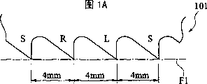
In above-mentioned underload saw, for example use shown in Figure 1A, Figure 1B, be that certain a pair of left and right sides swage set tooth L, these 3 teeth of R constitute a swage set structure by a straight-tooth S with towards the wrest of saw amount of left and right directions, this swage set structure is repeated to constitute, and it for example is the sawtooth 101 of 4mm that tooth pitch constitutes employing, when cutting diameter for example shown in Figure 3 is the solid material W of 50mm, can cut normally., use and above-mentioned same sawtooth 101, when cut for example shown in Figure 4, diameter and be 50mm, wall thickness, have the sawtooth 101 easy problems that collapse tooth for example for the tubing W of 3mm.
Its reason is, because the tooth pitch of sawtooth 101 is 4mm and the wall thickness of tubing W is 3mm, simultaneously, the speed into of cutting of sawtooth 101 approaches the speed of the free-falling of frame load G, under this machining condition, when the cutting of sawtooth 101 arrives near the center of tubing W, workpiece W will enter between the tooth top and tooth top of sawtooth 101, and rapid free-falling takes place, because of producing the excessive input of cutting, collapse the tooth phenomenon easily.
Shown in Fig. 2 A, Fig. 2 B, use the tooth pitch sawtooth 103 littler to cut as the existing method that addresses this problem usually than the wall thickness of tubing W.Shown in Figure 5 use sawtooth 103 (sawtooth shown in Fig. 2 A, Fig. 2 B) cutting wall thickness that tooth pitch constitutes 2mm to be 3mm, diameter state as the tubing W of 50mm.
Under this condition, because the tooth pitch of sawtooth 103 is 2mm, less than tubing W is the wall thickness of 3mm, therefore, even sawtooth 103 arrives near the center of tubing, workpiece W can not enter between the tooth top and tooth top of sawtooth 103 yet, therefore rapid free-falling can not take place, so can cut normally yet.
Yet, state in the use same sawtooth 103 just tooth pitch be that sawtooth 103 (sawtooth shown in Fig. 2 A, Fig. 2 B) cutting diameter of 2mm is when being the solid material W (shown in Figure 3 be cut material) of 50mm, because the tooth pitch of sawtooth 103 is compared with the diameter of workpiece W, very little, because of rapid free-falling not taking place, so excessive cutting into can not take place., the relative length of cut of workpiece W, the number of teeth of the sawtooth 103 that works is many more, then each tooth to workpiece W to cut input just few more.For this reason, the occasion that constitutes the solid material W of sawtooth 101 cuttings of 4mm with the tooth pitch of employing shown in Figure 1A, Figure 1B is compared, and exists long problem of cutting time.
According to above-mentioned, when cut-out solid material or tubing etc. are cut material, must change sawtooth according to shape, the size of workpiece W with proper tooth distance, exist the time of increase sawtooth replacing and the problem of time.
Therefore, for example in construction site etc., when cutting off the workpiece that varies as described above, can not ignore the shape according to workpiece, spent time and the time of sawtooth that size is changed different tooth pitches, in addition, even for the method that purpose that tooth is adopts the sawtooth of installing less tooth pitch is in advance collapsed in prevention, at this moment, can not ignore the elongated problem of cutting time that exists when cutting off the bigger workpiece of length of cut.
The present invention is for solving above-mentioned technical problem, provide a kind of no matter be length of cut more greatly or the less workpiece of length of cut, all can not collapse the sawtooth of the efficient cut-out of tooth.
Summary of the invention
To achieve these goals, the sawtooth of the 1st aspect is according to the present invention, the 1st tooth group of the left and right sides swage set tooth of the wrest of saw about will having straight-tooth and carrying out suitably constitutes repeatedly with the swage set structure that the 2nd tooth group with left and right sides swage set tooth of the wrest of saw about carrying out is combined, wherein, the wrest of saw amount of the left and right sides swage set tooth among described the 2nd tooth group is arranged to littler or equal than the wrest of saw amount of the left and right sides swage set tooth among described the 1st tooth group.
The sawtooth of the 2nd aspect is according to the present invention, the 1st tooth group of the left and right sides swage set tooth of the wrest of saw about will having straight-tooth and carrying out suitably constitutes repeatedly with the swage set structure that the 2nd tooth group with left and right sides swage set tooth of the wrest of saw about carrying out is combined, wherein, described the 2nd tooth group's tooth depth is arranged to be lower than described the 1st tooth group's tooth depth.
The sawtooth of the 3rd aspect is according to the present invention, in the sawtooth aspect the 2nd according to the present invention, the wrest of saw amount of the left and right sides swage set tooth among described the 2nd tooth group is arranged to littler or equal than the wrest of saw amount of the left and right sides swage set tooth among described the 1st tooth group.
The sawtooth of the 4th aspect is according to the present invention, to have straight-tooth at least and carry out about the 1st tooth group of pair of right and left swage set tooth of wrest of saw and the swage set structure that the 2nd tooth group is combined suitably constitute repeatedly, wherein, the tooth depth of sawtooth among described the 2nd tooth group is arranged to be lower than the tooth depth of sawtooth among described the 1st tooth group, the tooth top tooth pitch that comprises sawtooth groove among described the 2nd tooth group is littler than the tooth top tooth pitch that comprises sawtooth groove among described the 1st tooth group, and, the wrest of saw amount of the left and right sides swage set tooth among described the 2nd tooth group is arranged to equate with the wrest of saw amount of left and right sides swage set tooth among described the 1st tooth group or little.
The sawtooth of the 5th aspect is according to the present invention, to have straight-tooth at least and carry out about wrest of saw pair of right and left swage set tooth the 1st tooth group and have the swage set structure that the 2nd tooth group of pair of right and left swage set tooth at least combined and suitably constitute repeatedly, wherein, the tooth depth of sawtooth among described the 2nd tooth group is arranged to be lower than the tooth depth of sawtooth among described the 1st tooth group, the tooth top tooth pitch that comprises sawtooth groove among described the 2nd tooth group is littler than the tooth top tooth pitch that comprises sawtooth groove among described the 1st tooth group, and, the wrest of saw amount of the left and right sides swage set tooth among described the 2nd tooth group is arranged to equate with the wrest of saw amount of left and right sides swage set tooth among described the 1st tooth group or little.
The sawtooth of the 6th aspect is according to the present invention, and according to the sawtooth of either side in above-mentioned the 1st~the 5th aspect, wherein, described the 2nd tooth group has straight-tooth, and is arranged to identical with described the 2nd tooth group's the number of teeth described the 1st tooth group's the number of teeth.
The sawtooth of the 7th aspect is according to the present invention, according to the sawtooth of either side in above-mentioned the 1st~the 6th aspect, wherein, the number of teeth of described the 1st tooth group's left and right sides swage set tooth is arranged to equate with the number of teeth of described the 2nd tooth group's left and right sides swage set tooth.
The sawtooth of the 8th aspect is according to the present invention, and according to the sawtooth of either side in above-mentioned the 1st~the 7th aspect, wherein, described the 1st tooth group and the 2nd tooth flock-mate are for configuration.
The sawtooth of the 9th aspect is according to the present invention, and according to the sawtooth of either side in above-mentioned the 1st~the 8th aspect, wherein, the 2nd tooth group's the number of teeth is more than the 1st tooth group's the number of teeth.
The sawtooth of the 10th aspect is according to the present invention, and according to the sawtooth of either side in above-mentioned the 1st~the 9th aspect, wherein, the 1st tooth group's the number of teeth is more than the 2nd tooth group's the number of teeth.
The sawtooth of the 11st aspect is according to the present invention, and according to the sawtooth of either side in above-mentioned the 1st~the 10th aspect, wherein, the swage set tooth interior equidirectional swage set tooth that carries out wrest of saw in the left and right sides is configuration continuously among described the 1st tooth group and described the 2nd tooth group.
The sawtooth of the 12nd aspect is according to the present invention, and according to the sawtooth of either side in above-mentioned the 1st~the 10th aspect, wherein, the swage set tooth interior equidirectional swage set tooth that carries out wrest of saw in the left and right sides is discontinuous configuration among described the 1st tooth group and described the 2nd tooth group.
The sawtooth of the 13rd aspect is according to the present invention, and according to the sawtooth of either side in above-mentioned the 1st~the 12nd aspect, wherein, the tooth pitch of described each between cog is not wait tooth pitch.
The sawtooth of the 14th aspect is according to the present invention, and according to the sawtooth of either side in above-mentioned the 1st~the 13rd aspect, wherein, the described tooth pitch that do not wait is 2 kinds of tooth pitches.
The sawtooth of the 15th aspect is according to the present invention, and according to the sawtooth of either side in above-mentioned the 1st~the 14th aspect, wherein, the difference of height of described the 1st tooth group's tooth and described the 2nd tooth group's tooth is below the 0.2mm.
The sawtooth of the 16th aspect is according to the present invention, and according to the sawtooth of either side in above-mentioned the 1st~the 15th aspect, wherein, the bottom of the sawtooth groove among the bottom of the sawtooth groove among described the 2nd tooth group and described the 1st tooth group is compared, and is positioned at the tooth top side.
The sawtooth of the 17th aspect is according to the present invention, and according to the above-mentioned the 4th or the sawtooth of the 5th aspect, wherein, saw-tooth arrangement is in described the 1st tooth group between the sawtooth among described the 2nd tooth group.
As the above, employing is according to sawtooth of the present invention, each sawtooth that will have the 1st tooth group of higher straight-tooth of tooth depth and left and right sides swage set tooth is made up with each sawtooth of the 2nd tooth group with the lower and left and right sides swage set tooth that the wrest of saw amount is littler than the wrest of saw amount of the 1st tooth group's swage set tooth of tooth depth and is constituted the swage set structure.
Therefore, can easily dispose the cutting of the cutting of solid material etc. and tubing etc., and can not collapse tooth ground and cut efficiently, can obtain to overcome as the aforementioned the sawtooth of problem in the past.
Description of drawings
Figure 1A represents the front view of the tooth top shape part of sawtooth in the past,
Figure 1B represents the vertical view of the tooth top shape part of the sawtooth in the past shown in Figure 1A,
Fig. 2 A represents the front view of the tooth top shape part of sawtooth in the past,
The vertical view of the tooth top shape part of the sawtooth in the past shown in Fig. 2 B presentation graphs 2A,
Fig. 3 is the state diagram when cutting solid material of the sawtooth of 4mm for explanation with tooth pitch,
Fig. 4 for explanation with tooth pitch be the sawtooth of 4mm to cut wall thickness be the state diagram of 3mm tubing,
Fig. 5 for explanation with tooth pitch be the sawtooth of 2mm to cut wall thickness be the state diagram of 3mm tubing,
Fig. 6 A represents the front view of the sawtooth tooth top shape part of the present invention the 1st embodiment,
The vertical view of the sawtooth tooth top shape part shown in Fig. 6 B presentation graphs 6A,
The vertical view of the tooth top shape change style of the sawtooth shown in Fig. 6 C presentation graphs 6B,
Fig. 7 A represents the front view of the sawtooth tooth top shape part of the present invention the 2nd embodiment,
The vertical view of the sawtooth tooth top shape part shown in Fig. 7 B presentation graphs 7A,
The vertical view of the sawtooth tooth top shape change style shown in Fig. 7 C presentation graphs 7B,
Fig. 8 A represents the front view of the sawtooth tooth top shape part of the present invention the 3rd embodiment,
The vertical view of the sawtooth tooth top shape part shown in Fig. 8 B presentation graphs 8A,
Fig. 9 A represents the front view of the sawtooth tooth top shape part of the present invention the 4th embodiment,
The vertical view of the sawtooth tooth top shape part shown in Fig. 9 B presentation graphs 9A,
Figure 10 A represents the front view of the sawtooth tooth top shape part of the present invention the 5th embodiment,
The vertical view of the sawtooth tooth top shape part shown in Figure 10 B presentation graphs 10A,
Figure 11 A represents the front view of the sawtooth tooth top shape part of the present invention the 6th embodiment,
The vertical view of the sawtooth tooth top shape part shown in Figure 11 B presentation graphs 11A,
Figure 12 A represents the front view of the sawtooth tooth top shape part of the present invention the 7th embodiment,
The vertical view of the sawtooth tooth top shape part shown in Figure 12 B presentation graphs 12A,
Figure 13 A represents the front view of the sawtooth tooth top shape part of the present invention the 8th embodiment,
The vertical view of the sawtooth tooth top shape part shown in Figure 13 B presentation graphs 13A,
Figure 14 A represents the front view of the sawtooth tooth top shape part of the present invention the 9th embodiment,
The vertical view of the sawtooth tooth top shape part shown in Figure 14 B presentation graphs 14A,
The vertical view of the sawtooth tooth top shape change style shown in Figure 14 C presentation graphs 14B,
Figure 15 A represents the front view of the sawtooth tooth top shape part of the present invention the 10th embodiment,
The vertical view of the sawtooth tooth top shape part shown in Figure 15 B presentation graphs 15A,
The vertical view of the sawtooth tooth top shape change style shown in Figure 15 C presentation graphs 15B.
The specific embodiment
Below, embodiments of the invention are described with reference to the accompanying drawings, the sawtooth in following examples is by move the machining of carrying out workpiece to right in each figure.
With reference to Fig. 6 A, Fig. 6 B, constituting of the sawtooth 1 of the present invention the 1st embodiment, to have relative sawtooth 1, not carry out the straight-tooth S of wrest of saw and wrest of saw amount to left and right direction at left and right directions (thickness direction of sawtooth 1) big (in other words, the saw kerf width broad) a pair of left and right sides swage set tooth Lw, the 1st tooth group of Rw (sawtooth that belongs to the 1st tooth group is represented with symbol A), with have the aforementioned swage set tooth Lw of wrest of saw amount about than above-mentioned the 1st tooth group A, the pair of right and left swage set tooth Ln of the wrest of saw amount little (in other words, saw kerf width is narrow) of Rw, the swage set structure of the 2nd tooth group of Rn (sawtooth that belongs to the 2nd tooth group is represented with symbol B) combination suitably repeats to form.
The mode cutting workpiece W that sawtooth 1 is walked in the drawings from left to right.At this moment, in this machining operation, tooth Lw, the Ln of above-mentioned swage set structure, Rw, Rn, S, S contact with said workpiece W according to the order of tooth Lw, Ln, Rw, Rn, S, S, carry out machining.
In the sawtooth 1 shown in Fig. 6 A, Fig. 6 B, as the 1st tooth group A, amounting to 4 teeth by 2 straight-tooth S with bigger identical a pair of swage set tooth Lw, the Rw in the left and right sides of wrest of saw amount constitutes, as the 2nd tooth group B, pair of right and left swage set tooth Ln, the Rn littler than left and right sides swage set tooth Lw, the Rw of the 1st tooth group A add up to 2 teeth to constitute by the wrest of saw amount, by the combination of the 1st tooth group A and the 2nd tooth group B, constitute the swage set structure.And each tooth top space width P1 equates, for example is arranged to 2mm.
Use the sawtooth 1 of above-mentioned formation, when cutting the long workpiece W of the such length of cut of solid material for example shown in Figure 3, because the wrest of saw amount of left and right sides swage set tooth Ln, the Rn of the 2nd tooth group B is littler than left and right sides swage set tooth Lw, the Rw's of the 1st tooth group A, when widening the cutting of cutting slot of workpiece W, the shear action of playing is little.Just the little amount of its shear action tooth pitch that just in time becomes sawtooth constitutes whether become big.Promptly, ignore when giving little the 2nd tooth group B of shear action, give the interval of the sawtooth of more cutting, becoming mainly is left swage set tooth Lw and the interval of right swage set tooth Rw and the interval of right swage set tooth Rw and straight-tooth S of carrying out the 1st tooth group A of stock removal action, just in time becomes the style by the sawtooth cutting workpiece W with bigger tooth pitch (P1 * 2).And be original tooth pitch P1 between straight-tooth S, the S.
Therefore, use the sawtooth 1 of present embodiment and the sawtooth in the past 103 shown in Fig. 2 A, Fig. 2 B, in the speed of travel of band sawing machine, sawtooth, cut under the identical situation such as the machining condition of into load etc., cut solid material for example shown in Figure 3, with both relatively, will lack the break time of the sawtooth 1 of present embodiment.
In addition, in above-mentioned working angles, sawtooth 1 be the sawtooth tooth pitch for the condition of the tooth pitch of (P * 2) and tooth pitch P1 under cutting workpiece W, therefore, the resonance of sawtooth in the time of can suppressing to cut suppresses the generation of noise.In addition, equate that by the swage set tooth about making the component that acts on the left and right directions on the sawtooth offsets.
Also comprise the sawtooth in the past 101 shown in Figure 1A, Figure 1B, come the comparison cutting time, just become sawtooth 101<sawtooth 1<sawtooth 103, when cutting off solid material, compare, improved the cutting time with the sawtooth in the past 103 shown in Fig. 2 A, Fig. 2 B.
In addition, use the sawtooth 1 shown in Fig. 6 A, Fig. 6 B, during the such workpiece W of as shown in Figure 5 tubing of cutting, be the tubing of 3mm with respect to wall thickness, the tooth pitch P1 of sawtooth is 2mm, less, even because sawtooth 1 arrives near the center of tubing, workpiece w can not enter between the tooth top and tooth top of sawtooth yet, yet not sharply free-falling, therefore can not collapse the tooth phenomenon, can cut normally.
Promptly, when the cutting workpiece, as when cutting solid material, have when cutting under the tendency of the diminishing situation in the big and speed of cutting into of cutting resistance, mainly the sawtooth with the 1st tooth group A is the main shear action of carrying out, and as during cutting tubing, less and when cutting under the variable big situation of the speed of cutting in cutting resistance, no matter carry out shear action jointly by the 1st tooth group and the 2nd tooth group both sides, be that long workpiece of length of cut or the short workpiece of length of cut all can not collapse tooth, can realize cutting off efficiently.As a result, not only save the trouble of changing sawtooth according to workpiece, also reduced the consumption of sawtooth.
And shown in Fig. 6 C, the wrest of saw amount of swage set tooth Ln, the Rn of the wrest of saw amount of swage set tooth Lw, Rw about the 1st tooth group A and the 2nd tooth group B also can be roughly the same.At this moment, can obtain effect as the aforementioned, simultaneously, because swage set tooth Ln, the Rn of the 2nd tooth group B will cut, therefore, the section of workpiece W becomes the style of repairing, and has further improved the precision of section.
With reference to Fig. 7 A, Fig. 7 B, the sawtooth 3 of expression the present invention the 2nd embodiment, for the sawtooth and the tooth depth of the sawtooth that is equivalent to the 2nd tooth group B of the 1st tooth group A in the sawtooth 1 of a kind of Fig. 6 of being equivalent to A, Fig. 6 B, Fig. 6 C be provided with difference of height H1's and sawtooth between have the sawtooth of the tooth pitch P1 that equates.
In other words, the tooth top of each sawtooth S, Lw, Rw with consistently dispose by the 1st imaginary line F1 shown in the chain-dotted line.And the tooth top of each sawtooth St, Ln, Rn with consistently dispose by the 2nd imaginary line F2 shown in the chain-dotted line.The difference of height of these the 1st imaginary line F1 and the 2nd imaginary line F2 is equivalent to the difference of height H1 of above-mentioned sawtooth tooth depth.
As above-mentioned, because the tooth top of the tooth top of each sawtooth S, Lw, Rw and each sawtooth St, Ln, Rn is provided with the configuration of difference of height H1 ground, so both sides' gash depth is different.That is to say that belong to the tooth depth lower (with (L) expression) of each sawtooth Ln, the Rn of the 2nd tooth group B, the groove of front side (being the right side among the figure, the upstream side of sawtooth moving direction) forms more shallow than the groove of the front side of each sawtooth St, Lw of belonging to the 1st tooth group A, Rw.So, lower and the groove front side is more shallow by making tooth depth, the rigidity that belongs to the sawtooth of the 2nd tooth group B is improved, even this sawtooth also can suppress the flexible of the wrest of saw direction due to the cutting resistance when the cutting workpiece, has improved cutting ability.
In addition, as the difference of height of the left and right sides swage set tooth of the left and right sides swage set tooth of the 1st tooth group A and the 2nd tooth group B, the swage set tooth that the wrest of saw amount of the 2nd tooth group B is little, its tooth depth is also lower.In other words, the swage set tooth that tooth depth is lower, the wrest of saw amount of the swage set tooth that its wrest of saw amount is more higher than tooth depth is little.
In more detail, as the 1st tooth group A, by the height of the straight-tooth S of tooth depth higher (with (H) expression) and tooth depth with (H) expression and wrest of saw amount bigger, about these 3 teeth of a pair of swage set tooth Lw, Rw of equating constitute.As the 2nd tooth group B, constitute than the low straight-tooth St of the tooth depth of the straight-tooth S of the 1st tooth group A and tooth depth these 3 teeth of pair of right and left swage set tooth Ln, Rn that tooth depth is low and the wrest of saw amount is little by tooth depth than left and right sides swage set tooth Lw, the Rw of the 1st tooth group A, straight-tooth is identical with the number of left and right sides swage set tooth, constitutes a swage set structure by 6 sawtooth of total of the 1st tooth group A and the 2nd tooth group B.And, the sawtooth alternate configurations of the sawtooth of the 1st tooth group A and the 2nd tooth group B.
In aforementioned sawtooth 3, amount H1 as the tooth top difference of height of the sawtooth of the sawtooth of the 1st tooth group A and the 2nd tooth group B, during as cutting solid material for example shown in Figure 3, length of cut is long more, cutting into, the cutting resistance of direction becomes big, and during the state that the speed into of cutting becomes less, mainly cut into shear action by each sawtooth of the 1st tooth group A, it is such when tubing as shown in Figure 5 cuts, the cutting resistance of cutting direction into is little and cut when into speed easily becomes big, with the 1st tooth group A and the two degree that all can cut shear action into of the 2nd tooth group B difference of height H1 is set.
In addition, although the amount H1 of difference of height is different because of the shape of the tooth pitch of sawtooth and workpiece W, size, kind etc.,, wish roughly below 0.2mm, when cutting metal, to be suitable particularly below 0.1mm according to various experiments.
In addition, in the sawtooth 1 of the 1st embodiment, constitute owing to the tooth depth that is the big swage set tooth of little swage set tooth of wrest of saw amount and wrest of saw amount is roughly the same, so the little swage set tooth of wrest of saw amount is compared stock removal action with big swage set tooth and also will be cut the into shear action of direction less usually.To this, in the sawtooth 3 of the 2nd embodiment, during the cutting solid material, each sawtooth Ln, Rn, the St of the 2nd tooth group B cut the into shear action of direction hardly, are cut by each sawtooth among the 1st tooth group A basically.Therefore, only pay close attention to the sawtooth of the 1st tooth group A that carries out shear action, tooth pitch becomes and is P1 * 2, and the sawtooth in the past 101 shown in Figure 1A, Figure 1B is such just.
Therefore, use the sawtooth 3 of the 2nd embodiment, it is identical to add the situation in man-hour in the speed of travel of band sawing machine, sawtooth, the machining condition and the sawtooth 1 residing cut-out of aforementioned the 1st embodiment of cutting into load etc., cutting solid material as shown in Figure 3, to the cutting time compare sawtooth 101 sawtooth 3<sawtooth 1<sawtooth 103.That is to say, in the cut-out of solid material, compare with the sawtooth 1 of the 1st embodiment shown in Fig. 6 A, Fig. 6 B, Fig. 6 C with the sawtooth in the past 103 shown in Fig. 2 A, Fig. 2 B, improved the cutting time, and roughly the same with the sawtooth in the past 101 shown in Figure 1A, Figure 1B.
In addition, use the sawtooth 3 shown in Fig. 7 A, Fig. 7 B, Fig. 7 C, during the such workpiece W of as shown in Figure 5 tubing of cutting, with respect to wall thickness is the tubing of 3mm, the tooth pitch P1 of sawtooth is 2mm, less, and the cutting resistance of direction diminishes, cuts under the situation of the big tendency of input change cutting into, that is, and and in the time of near the center of sawtooth 3 arrival tubing, the sawtooth of the 2nd tooth group B also together carries out shear action, workpiece W can not enter between the tooth top and tooth top of sawtooth 3, rapid free-falling can not take place, therefore, can not collapse tooth, can cut normally.
In addition, in above-mentioned sawtooth 3, also the wrest of saw amount of the swage set tooth of the swage set tooth of the 1st tooth group A and the 2nd tooth group B can be arranged to amount like that about equally shown in Fig. 7 C.At this moment, by finishing effect, can further improve the precision of section.
With reference to Fig. 8 A, Fig. 8 B, represented the sawtooth 5 of the present invention the 3rd embodiment, removed the sawtooth of the straight-tooth St of the 2nd tooth group B in the 2nd embodiment sawtooth 3 shown in Fig. 7 A, Fig. 7 B, Fig. 7 C, between sawtooth the sawtooth that waits tooth pitch P1.
In more detail, as the 1st tooth group A, by the higher straight-tooth S of 1 tooth depth and wrest of saw amount bigger about these 3 teeth of a pair of swage set tooth Lw, Rw of equating constitute, as the 2nd tooth group B, constitute by tooth depth tooth depth these 2 teeth of pair of right and left swage set tooth Ln, Rn low and that the wrest of saw amount is littler than the wrest of saw amount of swage set tooth Lw, Rw among the 1st tooth group A, constitute 1 swage set structure by 5 sawtooth of the total that is combined into of the sawtooth of the sawtooth of the 1st tooth group A and the 2nd tooth group B than left and right sides swage set tooth Lw, the Rw of the 1st tooth group A.
And, be H1 as the amount of the tooth top difference of height of the sawtooth of the sawtooth of the 1st tooth group A and the 2nd tooth group B, since identical with the sawtooth 3 of aforementioned the 2nd embodiment, omit its explanation at this.
In the sawtooth 5 of the 3rd embodiment, identical with the sawtooth 3 of the 2nd embodiment, during the cutting solid material, each swage set tooth Ln, Rn of the 2nd tooth group B carry out shear action hardly, are cut by each sawtooth that belongs to the 1st tooth group A basically.At this, only pay close attention to each sawtooth of the 1st tooth group A that mainly carries out shear action, with respect in the sawtooth 3 of the 2nd embodiment, the average tooth pitch of the sawtooth of swage set structure is 4mm, and in the sawtooth 5 of the 3rd embodiment, the average tooth pitch of sawtooth in the swage set structure is about 3.3mm (=(2+4+4)/3), and it is less just to become.
Therefore, use the sawtooth 5 of the 3rd embodiment, the speed of travel of band sawing machine, sawtooth, cut into load etc. machining condition identical with the sawtooth situation of the aforementioned the 1st and the 2nd embodiment, the cutting time of the solid material that cutting is shown in Figure 3 is compared sawtooth 101 sawtooth 3<sawtooth 5<sawtooth 1<sawtooth 103.That is to say, in the cut-out of solid material, the average tooth pitch of the 1st tooth group A is about 3.3mm, only little than the tooth pitch 4mm of the sawtooth in the past 101 shown in Figure 1A, Figure 1B, although the cutting time is longer than sawtooth 3, but compare with the sawtooth 1 of the 1st embodiment shown in Fig. 6 A, Fig. 6 B, Fig. 6 C with the sawtooth in the past 103 shown in Fig. 2 A, Fig. 2 B, improved the cutting time.
In addition, use the sawtooth 5 shown in Fig. 8 A, Fig. 8 B, during the such workpiece W of cutting tubing as shown in Figure 5, play the effect same, can not collapse tooth, can cut normally with the sawtooth 3 of the 2nd embodiment.
With reference to Fig. 9 A, Fig. 9 B, the sawtooth 7 of expression the present invention the 4th embodiment, roughly the same with the wrest of saw amount of left and right sides swage set tooth Ln, the Rn of left and right sides swage set tooth Lw, the Rw of the 1st tooth group A of the 3rd embodiment sawtooth 5 of Fig. 8 A, Fig. 8 B and the 2nd tooth group B, be the sawtooth that waits tooth pitch P1 between sawtooth.
In more detail, as the 1st tooth group A, constitute than big and higher these 3 teeth of pair of right and left swage set tooth Lw, Rw of tooth depth by a higher straight-tooth S and a wrest of saw amount of tooth depth, as the 2nd tooth group B, constitute than the left and right sides swage set tooth Lw of the 1st tooth group A, these 2 teeth of pair of right and left swage set tooth Ln, Rn that Rw is low and the wrest of saw amount is roughly the same by tooth depth, constitute a swage set structure by a plurality of sawtooth that will belong to the 1st tooth group A and 5 sawtooth that a plurality of sawtooth that belong to the 2nd tooth group B combine.
In the sawtooth 7 of above-mentioned formation, such when cutting solid material as shown in Figure 3, cutting resistance is big, during the less state of the speed of cutting into, swage set tooth Ln, Rn that the tooth depth of the 2nd tooth group B is lower carry out shear action hardly, but, higher swage set tooth Lw, the Rw of the tooth depth of the 1st tooth group A carries out shear action slightly as the side mode of the cutting slot of the cutting of nuzzling up, and by the finishing effect, improves the precision in cutting face.And because same with the sawtooth 3 of aforementioned the 2nd embodiment as the amount H1 of the tooth top difference of height of the sawtooth of the sawtooth of the 1st tooth group A and the 2nd tooth group B, at this, omission is to its explanation.
In addition, in the sawtooth 7 of the 4th embodiment, during the cutting solid material, same with the sawtooth 5 of the 3rd embodiment when only paying close attention to the sawtooth of the 1st tooth group A that mainly carries out shear action, in the swage set structure, the average tooth pitch of sawtooth is about 3.3mm.Therefore, the speed of travel of band sawing machine, sawtooth, cut into load etc. machining condition identical with the situation of aforementioned the 1st, the 2nd and the 3rd embodiment, cutting time during with cutting solid material shown in Figure 3 is compared sawtooth 101 sawtooth 3<sawtooth 5 sawtooth 7<sawtooth 1<sawtooth 103.
That is to say, in the cut-out of solid material, compare, improved the cutting time with the sawtooth 1 of sawtooth in the past 103 shown in Fig. 2 A, Fig. 2 B and the 1st embodiment shown in Figure 1.And it is roughly the same with the sawtooth 5 of the 3rd embodiment shown in Fig. 8 A, Fig. 8 B.
In addition, use the sawtooth 7 shown in Fig. 9 A, Fig. 9 B, during the such workpiece W of cutting tubing as shown in Figure 5, play the effect same, can not collapse tooth, can cut normally with the sawtooth 3 of the 2nd embodiment.
With reference to Figure 10 A, Figure 10 B, the sawtooth 9 of the 5th embodiment of the present invention, being that configuration sequence transposing with left and right sides swage set tooth Ln, the Rn of left and right sides swage set tooth Lw, the Rw of the 1st tooth group A in the sawtooth 5 of the 3rd embodiment shown in Figure 3 and the 2nd tooth group B forms, is the sawtooth that waits tooth pitch P1 between sawtooth.Because the sawtooth 5 of the 3rd embodiment shown in function and Fig. 8 A, Fig. 8 B much at one, omits more detailed description at this.
Each tooth configuration as the sawtooth of the sawtooth of sawtooth the 9, the 1st tooth group A of the 5th embodiment and the 2nd tooth group B can suitably be changed.At this moment, the sawtooth of the sawtooth of the 1st tooth group A and the 2nd tooth group B is discontinuous configuration at the swage set tooth of equidirectional.
Shown in Figure 11 A, Figure 11 B, the sawtooth 11 of the present invention the 6th embodiment is, in the 2nd tooth group B of the sawtooth 5 of the 3rd embodiment shown in Figure 3, appending left and right sides swage set tooth Ln2, the Rn2 that tooth depth is lower and the wrest of saw amount is little becomes the sawtooth with a plurality of sawtooth numbers, is the sawtooth that waits tooth pitch P1 between sawtooth.
In more detail, as the 1st tooth group A, by the higher straight-tooth S of tooth depth and wrest of saw amount bigger about these 3 teeth of a pair of swage set tooth Lw, Rw of equating constitute, as the 2nd tooth group B, constitute than the left and right sides swage set tooth Lw of the 1st tooth group A, pair of right and left swage set tooth Ln1, Ln2 and little a pair of left and right sides swage set tooth Rn1, these 4 teeth of Rn2 of wrest of saw amount that Rw is low and the wrest of saw amount is slightly little by tooth depth, the combination of sawtooth by the 1st tooth group A and the sawtooth of the 2nd tooth group B constitutes a swage set structure by adding up to 7 sawtooth.And, as the amount H1 of the tooth top difference of height of the sawtooth of the sawtooth of the 1st tooth group A and the 2nd tooth group B, be identical with the sawtooth 3 of aforesaid the 2nd embodiment, at this, omit its more detailed description.
In addition, in the sawtooth 11 of the 6th embodiment, same with the sawtooth 5 of the 3rd embodiment, when the cutting solid material, each sawtooth Ln1, Ln2, Rn1, Rn2 among the 2nd tooth group B carry out shear action hardly, are cut by each sawtooth S, Lw, Rw among the 1st tooth group A basically.Therefore, when only paying close attention to left and right sides swage set tooth Lw, the Rw of the 1st tooth group A that mainly carries out shear action, the interval of the interval of left and right sides swage set tooth Lw and Rw and swage set tooth Rw and straight-tooth S (P1 * 3=6mm) become big respectively, because just tooth pitch becomes big, the input of cutting of each sawtooth just becomes big, and then the load of each sawtooth change is big, and the sawtooth that tooth pitch is bigger is bad, so can adopt the less sawtooth of tooth pitch to constitute the structure of usefulness.
In addition, use the sawtooth 11 shown in Figure 11 A, Figure 11 B, during the such workpiece W of cutting tubing as shown in Figure 5, play the effect same, can not collapse tooth, can cut normally with the sawtooth 3 of the 2nd embodiment.
With reference to Figure 12 A, Figure 12 B, the sawtooth 13 of the present invention the 7th embodiment is, in the 1st tooth group A of the sawtooth 5 of the 3rd embodiment shown in Fig. 8 A, Fig. 8 B, appending left and right sides swage set tooth Lw2, the Rw2 that tooth depth is higher and the wrest of saw amount is bigger becomes the sawtooth with a plurality of sawtooth numbers, is the sawtooth that waits tooth pitch P1 between sawtooth.
In more detail, as the 1st tooth group A, by the higher straight-tooth S of tooth depth and two couples of swage set tooth Lw1, Lw2, Rw1, these 5 teeth of Rw2 of equating about tooth depth is higher and the wrest of saw amount is bigger constitute, as the 2nd tooth group B, be made of than the left and right sides swage set tooth Lw of the 1st tooth group A, these 2 teeth of pair of right and left swage set tooth Ln, Ln that Rw is low and the wrest of saw amount is little tooth depth, 7 sawtooth that add up to that combine of sawtooth by the 1st tooth group A and the sawtooth of the 2nd tooth group B constitute a swage set structure.
And the sawtooth 13 of the 7th embodiment has improved because of the left and right sides swage set tooth Lw of the 1st tooth group A of the sawtooth 11 of aforesaid Figure 11 A, Figure 11 B illustrated embodiment, the bigger shortcoming of tooth pitch of Rw.And,, because roughly the same,, omit it illustrated in greater detail at this with the sawtooth 5 of aforementioned the 3rd embodiment for the amount H1 of the tooth top difference of height of the sawtooth of the sawtooth of the shear action of solid material or tubing and the 1st tooth group A and the 2nd tooth group B.As mentioned above, can suitably change the sawtooth kind of formation the 1st tooth group A and sawtooth kind and the quantity of quantity and the 2nd tooth group B thereof.
With reference to Figure 13 A, Figure 13 B, the sawtooth 15 of the present invention the 8th embodiment is that the structure of difference of height of the left and right sides swage set tooth Ln with left and right sides swage set tooth Lw, the Rw of the 1st tooth group A of the sawtooth 5 of the 3rd embodiment shown in Fig. 8 A, Fig. 8 B and the 2nd tooth group B, swage set structure that Rn combines and tooth depth is identical, and it is not wait tooth pitch by what 2 kinds of tooth pitches combined that the tooth pitch of sawtooth constitutes.
By not waiting tooth pitch, can produce the new effect of noise when reducing cutting.In Figure 13 A,, by constituting multiple class tooth pitch, because of the resonance due to the vibration, can further reduce the cutting noise in the time of can suppressing to cut effectively although the expression tooth pitch is the sawtooth of P1 and these 2 kinds of formations of P2.
In addition, with respect to the shear action of solid material or tubing, and the amount H1 of the tooth top difference of height of the sawtooth of the sawtooth of the 1st tooth group A and the 2nd tooth group B, roughly the sawtooth 5 with aforementioned the 3rd embodiment is identical, omits its explanation at this.
With reference to Figure 14 A, Figure 14 B, the sawtooth 17 of the present invention the 9th embodiment constitutes the swage set structure by the 1st tooth group A that will have straight-tooth S1, left and right sides swage set tooth Lw, these 3 teeth of Rw with 6 sawtooth of the combined total that forms of the 2nd tooth group B that has straight-tooth S2, left and right sides swage set tooth Ln, these 3 teeth of Rn equally.
Compare with the tooth depth of the straight-tooth S1 that belongs to aforementioned the 1st tooth group A, left and right sides swage set tooth Lw, Rw, the tooth depth of straight-tooth S2, left and right sides swage set tooth Ln, Rn that belongs to the 2nd tooth group B is lower, and the groove of front side is identical with aforesaid each embodiment, forms more shallow than the front side groove of each sawtooth that belongs to the 1st tooth group A.In addition, the 1st tooth group A is identical with the difference of height H1 of the 2nd tooth group B and the difference of height of aforesaid each sawtooth.In addition, the wrest of saw amount that will belong to left and right sides swage set tooth Ln, the Rn of the 2nd tooth group B is designed to littler or equal than the wrest of saw amount of the left and right sides swage set tooth Lw, the Rw that belong to aforementioned the 1st tooth group A, and, belong to each sawtooth S1, Lw, the Rw of the 1st tooth group A and belong to each sawtooth S2, Ln, the Rn alternate configurations of the 2nd tooth group B.
In addition, in sawtooth 17, the tooth top tooth pitch P1 that includes the groove of each sawtooth S2, Ln of belonging to the 2nd tooth group B, Rn is arranged to the tooth top tooth pitch P2 less than the groove that includes each sawtooth S1, Lw of belonging to the 1st tooth group A, Rw.In addition, belong to left and right sides swage set tooth Lw, the Rw of the 1st tooth group A and belong to the 2nd tooth group B left and right sides swage set tooth Ln, Rn configuration relation as shown in Figure 14B, can be so that carry out the swage set tooth of same direction finishing and dispose continuously in abutting connection with the ground mode with paired, also can shown in Figure 14 C, the different swage set tooth of finishing direction be disposed continuously in the mode of paired adjacency.
In the sawtooth 17 of above-mentioned formation, when cutting off as shown in Figure 3 solid material, mainly carry out cutwork by each sawtooth S1, the Lw, the Rw that belong to the 1st tooth group A, and in cutting off such situation such as tubing, each sawtooth S2, the Ln, the Rn that belong to each sawtooth S1, Lw, the Rw of the 1st tooth group A and belong to the 2nd tooth group B carry out the cutting of workpiece jointly, thereby can easily carry out the cut-out of solid material and the cut-out of tubing.
With reference to Figure 15 A, Figure 15 B, the sawtooth 19 of the present invention the 10th embodiment is identical with the configuration of the sawtooth 15 of aforementioned the 8th embodiment and swage set structure or each sawtooth, but the relief angle of tooth top is made two sections, and the ditch tankage is strengthened, thereby is difficult to take place the smear metal clogging.In addition, the shear action of each sawtooth that belongs to the 2nd tooth group B is less than the shear action of each sawtooth that belongs to the 1st tooth group A, therefore, the degree of depth of front side groove of each sawtooth that belongs to the 2nd tooth group B becomes the formation that is fit to each sawtooth function than the depth as shallow of the groove of each the sawtooth front side that belongs to the 1st tooth group A.
In addition, the configuration relation of left and right sides swage set tooth Ln, Rn that belongs to left and right sides swage set tooth Lw, the Rw of the 1st tooth group A and belong to the 2nd tooth group B is shown in Figure 15 B, can so that the swage set tooth that carries out the finishing of same direction dispose continuously in the mode of paired adjacency, also can shown in Figure 15 C, the different swage set tooth of finishing direction be disposed continuously in the mode of paired adjacency.
In order further to understand the explanation of aforementioned sawtooth 17,19, the kind and the quantity that belong to each sawtooth of the 1st tooth group A are arbitrarily, and the kind and the quantity that belong to each sawtooth of the 2nd tooth group B also are arbitrarily, when each sawtooth with each sawtooth of the 1st tooth group A and the 2nd tooth group B constituted the swage set structure, the number of wishing to be included in the left swage set tooth in this swage set structure was what equate with the number of right swage set tooth.In addition, in the swage set structure, the tooth top tooth pitch is not limited to these 2 kinds of aforementioned P1, P2, also other tooth pitches can be combined, and for example, can make the swage set structure constitute all differences of all tooth pitches.
Claims (51)
1. sawtooth, the 1st tooth group of the left and right sides swage set tooth of the wrest of saw about will having straight-tooth and carrying out suitably constitutes repeatedly with the swage set structure that the 2nd tooth group with left and right sides swage set tooth of the wrest of saw about carrying out is combined, it is characterized in that, the wrest of saw amount of the left and right sides swage set tooth among described the 2nd tooth group is arranged to littler or equal than the wrest of saw amount of the left and right sides swage set tooth among described the 1st tooth group.
2. according to the described sawtooth of claim 1, it is characterized in that described the 2nd tooth group has straight-tooth, and be arranged to identical with described the 2nd tooth group's the number of teeth described the 1st tooth group's the number of teeth.
3. according to the described sawtooth of claim 2, it is characterized in that, the number of teeth of described the 1st tooth group's left and right sides swage set tooth is arranged to equate with the number of teeth of described the 2nd tooth group's left and right sides swage set tooth.
4. according to the described sawtooth of claim 3, it is characterized in that described the 1st tooth group and the 2nd tooth flock-mate are for configuration.
5. according to the described sawtooth of claim 4, it is characterized in that the 2nd tooth group's the number of teeth is more than the 1st tooth group's the number of teeth.
6. according to the described sawtooth of claim 5, it is characterized in that the 1st tooth group's the number of teeth is more than the 2nd tooth group's the number of teeth.
7. according to the described sawtooth of claim 6, it is characterized in that the swage set tooth interior equidirectional swage set tooth that carries out wrest of saw in the left and right sides is configuration continuously among described the 1st tooth group and described the 2nd tooth group.
8. according to the described sawtooth of claim 7, it is characterized in that the swage set tooth interior equidirectional swage set tooth that carries out wrest of saw in the left and right sides is discontinuous configuration among described the 1st tooth group and described the 2nd tooth group.
9. according to the described sawtooth of claim 8, it is characterized in that the tooth pitch of described each between cog is not wait tooth pitch.
10. according to the described sawtooth of claim 9, it is characterized in that the described tooth pitch that do not wait is 2 kinds of tooth pitches.
11., it is characterized in that the difference of height of described the 1st tooth group's tooth and described the 2nd tooth group's tooth is below the 0.2mm according to the described sawtooth of claim 10.
12., it is characterized in that the bottom of the sawtooth groove among the bottom of the sawtooth groove among described the 2nd tooth group and described the 1st tooth group is compared, and is positioned at the tooth top side according to the described sawtooth of claim 11.
13. sawtooth, the 1st tooth group of the left and right sides swage set tooth of the wrest of saw about will having straight-tooth and carrying out suitably constitutes repeatedly with the swage set structure that the 2nd tooth group with left and right sides swage set tooth of the wrest of saw about carrying out is combined, it is characterized in that, described the 2nd tooth group's tooth depth is arranged to be lower than described the 1st tooth group's tooth depth.
14. according to the described sawtooth of claim 13, it is characterized in that, the wrest of saw amount of the left and right sides swage set tooth among described the 2nd tooth group be arranged to littler or equal than the wrest of saw amount of the left and right sides swage set tooth among described the 1st tooth group.
15., it is characterized in that described the 2nd tooth group has straight-tooth according to the described sawtooth of claim 13, and be arranged to identical with described the 2nd tooth group's the number of teeth described the 1st tooth group's the number of teeth.
16. according to the described sawtooth of claim 15, it is characterized in that, the number of teeth of described the 1st tooth group's left and right sides swage set tooth be arranged to equate with the number of teeth of described the 2nd tooth group's left and right sides swage set tooth.
17., it is characterized in that described the 1st tooth group and the 2nd tooth flock-mate are for configuration according to the described sawtooth of claim 16.
18., it is characterized in that the 2nd tooth group's the number of teeth is more than the 1st tooth group's the number of teeth according to the described sawtooth of claim 17.
19., it is characterized in that the 1st tooth group's the number of teeth is more than the 2nd tooth group's the number of teeth according to the described sawtooth of claim 18.
20., it is characterized in that the swage set tooth interior equidirectional swage set tooth that carries out wrest of saw in the left and right sides is configuration continuously among described the 1st tooth group and described the 2nd tooth group according to the described sawtooth of claim 19.
21., it is characterized in that the swage set tooth interior equidirectional swage set tooth that carries out wrest of saw in the left and right sides is discontinuous configuration among described the 1st tooth group and described the 2nd tooth group according to the described sawtooth of claim 20.
22., it is characterized in that the tooth pitch of described each between cog is not wait tooth pitch according to the described sawtooth of claim 21.
23., it is characterized in that the described tooth pitch that do not wait is 2 kinds of tooth pitches according to the described sawtooth of claim 22.
24., it is characterized in that the difference of height of described the 1st tooth group's tooth and described the 2nd tooth group's tooth is below the 0.2mm according to the described sawtooth of claim 23.
25., it is characterized in that the bottom of the sawtooth groove among the bottom of the sawtooth groove among described the 2nd tooth group and described the 1st tooth group is compared, and is positioned at the tooth top side according to the described sawtooth of claim 24.
26. sawtooth, to have straight-tooth at least and carry out about the 1st tooth group of pair of right and left swage set tooth of wrest of saw and the swage set structure that the 2nd tooth group is combined suitably constitute repeatedly, it is characterized in that, the tooth depth of sawtooth among described the 2nd tooth group is arranged to be lower than the tooth depth of sawtooth among described the 1st tooth group, the tooth top tooth pitch that comprises sawtooth groove among described the 2nd tooth group is littler than the tooth top tooth pitch that comprises sawtooth groove among described the 1st tooth group, and, the wrest of saw amount of the left and right sides swage set tooth among described the 2nd tooth group is arranged to equate with the wrest of saw amount of left and right sides swage set tooth among described the 1st tooth group or little.
27., it is characterized in that saw-tooth arrangement is in described the 1st tooth group between the sawtooth among described the 2nd tooth group according to the described sawtooth of claim 26.
28., it is characterized in that described the 2nd tooth group has straight-tooth according to the described sawtooth of claim 27, and described the 1st tooth group's the number of teeth be arranged to the identical number of teeth with described the 2nd tooth group's the number of teeth.
29. according to the described sawtooth of claim 28, it is characterized in that, the number of teeth of described the 1st tooth group's left and right sides swage set tooth be arranged to equate the number of teeth with the number of teeth of described the 2nd tooth group's left and right sides swage set tooth.
30., it is characterized in that described the 1st tooth group and the 2nd tooth flock-mate are for configuration according to the described sawtooth of claim 29.
31., it is characterized in that the 2nd tooth group's the number of teeth is more than the 1st tooth group's the number of teeth according to the described sawtooth of claim 30.
32., it is characterized in that the 1st tooth group's the number of teeth is more than the 2nd tooth group's the number of teeth according to the described sawtooth of claim 31.
33., it is characterized in that the swage set tooth interior equidirectional swage set tooth that carries out wrest of saw in the left and right sides is configuration continuously among described the 1st tooth group and described the 2nd tooth group according to the described sawtooth of claim 32.
34., it is characterized in that the swage set tooth interior equidirectional swage set tooth that carries out wrest of saw in the left and right sides is discontinuous configuration among described the 1st tooth group and described the 2nd tooth group according to the described sawtooth of claim 33.
35., it is characterized in that the tooth pitch of described each between cog is not wait tooth pitch according to the described sawtooth of claim 34.
36., it is characterized in that the described tooth pitch that do not wait is 2 kinds of tooth pitches according to the described sawtooth of claim 35.
37., it is characterized in that the difference of height of described the 1st tooth group's tooth and described the 2nd tooth group's tooth is below the 0.2mm according to the described sawtooth of claim 36.
38., it is characterized in that the bottom of the sawtooth groove among the bottom of the sawtooth groove among described the 2nd tooth group and described the 1st tooth group is compared, and is positioned at the tooth top side according to the described sawtooth of claim 37.
39. sawtooth, to have straight-tooth at least and carry out about wrest of saw pair of right and left swage set tooth the 1st tooth group and have the swage set structure that the 2nd tooth group of pair of right and left swage set tooth at least combined and suitably constitute repeatedly, it is characterized in that, the tooth depth of sawtooth among described the 2nd tooth group is arranged to be lower than the tooth depth of sawtooth among described the 1st tooth group, the tooth top tooth pitch that comprises sawtooth groove among described the 2nd tooth group is littler than the tooth top tooth pitch that comprises sawtooth groove among described the 1st tooth group, and, the wrest of saw amount of the left and right sides swage set tooth among described the 2nd tooth group is arranged to equate with the wrest of saw amount of left and right sides swage set tooth among described the 1st tooth group or little.
40., it is characterized in that saw-tooth arrangement is in described the 1st tooth group between the sawtooth among described the 2nd tooth group according to the described sawtooth of claim 39.
41., it is characterized in that described the 2nd tooth group has straight-tooth according to the described sawtooth of claim 40, and described the 1st tooth group's the number of teeth be arranged to the identical number of teeth with described the 2nd tooth group's the number of teeth.
42. according to the described sawtooth of claim 41, it is characterized in that, the number of teeth of described the 1st tooth group's left and right sides swage set tooth be arranged to equate with the number of teeth of described the 2nd tooth group's left and right sides swage set tooth.
43., it is characterized in that described the 1st tooth group and the 2nd tooth flock-mate are for configuration according to the described sawtooth of claim 42.
44., it is characterized in that the 2nd tooth group's the number of teeth is more than the 1st tooth group's the number of teeth according to the described sawtooth of claim 43.
45., it is characterized in that the 1st tooth group's the number of teeth is more than the 2nd tooth group's the number of teeth according to the described sawtooth of claim 44.
46., it is characterized in that the swage set tooth interior equidirectional swage set tooth that carries out wrest of saw in the left and right sides is configuration continuously among described the 1st tooth group and described the 2nd tooth group according to the described sawtooth of claim 45.
47., it is characterized in that the swage set tooth interior equidirectional swage set tooth that carries out wrest of saw in the left and right sides is discontinuous configuration among described the 1st tooth group and described the 2nd tooth group according to the described sawtooth of claim 46.
48., it is characterized in that the tooth pitch of described each between cog is not wait tooth pitch according to the described sawtooth of claim 47.
49., it is characterized in that the described tooth pitch that do not wait is 2 kinds of tooth pitches according to the described sawtooth of claim 48.
50., it is characterized in that the difference of height of described the 1st tooth group's tooth and described the 2nd tooth group's tooth is below the 0.2mm according to the described sawtooth of claim 49.
51., it is characterized in that the bottom of the sawtooth groove among the bottom of the sawtooth groove among described the 2nd tooth group and described the 1st tooth group is compared, and is positioned at the tooth top side according to the described sawtooth of claim 50.
Applications Claiming Priority (3)
| Application Number | Priority Date | Filing Date | Title |
|---|---|---|---|
| JP2000359937 | 2000-11-27 | ||
| JP359937/00 | 2000-11-27 | ||
| JP359937/2000 | 2000-11-27 |
Publications (2)
| Publication Number | Publication Date |
|---|---|
| CN1476363A true CN1476363A (en) | 2004-02-18 |
| CN100357052C CN100357052C (en) | 2007-12-26 |
Family
ID=18831616
Family Applications (1)
| Application Number | Title | Priority Date | Filing Date |
|---|---|---|---|
| CNB018195377A Expired - Fee Related CN100357052C (en) | 2000-11-27 | 2001-11-22 | Saw blade |
Country Status (9)
| Country | Link |
|---|---|
| US (1) | US7568416B2 (en) |
| EP (1) | EP1354655A4 (en) |
| JP (1) | JP4133325B2 (en) |
| KR (1) | KR100546021B1 (en) |
| CN (1) | CN100357052C (en) |
| AU (1) | AU2002224076A1 (en) |
| RU (1) | RU2248261C1 (en) |
| TW (1) | TW494032B (en) |
| WO (1) | WO2002042028A1 (en) |
Cited By (4)
| Publication number | Priority date | Publication date | Assignee | Title |
|---|---|---|---|---|
| CN101594962B (en) * | 2006-11-24 | 2012-10-03 | Oc欧瑞康巴尔斯公司 | Saw band and method for producing a saw band |
| US8621972B2 (en) | 2008-08-20 | 2014-01-07 | Amada Company, Limited | Band saw blade |
| CN104507612A (en) * | 2012-07-17 | 2015-04-08 | 株式会社天田 | Saw blade and saw teeth arrangement method |
| CN111299701A (en) * | 2020-03-31 | 2020-06-19 | 湖南泰嘉新材料科技股份有限公司 | Band saw blade |
Families Citing this family (37)
| Publication number | Priority date | Publication date | Assignee | Title |
|---|---|---|---|---|
| DE10063567A1 (en) * | 2000-12-20 | 2002-07-04 | Scintilla Ag | sawblade |
| AU2003271157A1 (en) * | 2002-10-10 | 2004-05-04 | Amada Company, Limited | Saw blade |
| EP1470884B1 (en) * | 2003-04-25 | 2007-12-19 | Kapman AB | Bandsaw blade |
| SE526794C2 (en) * | 2004-03-11 | 2005-11-08 | Kapman Ab | Wood saw blade |
| US20050211046A1 (en) * | 2004-03-26 | 2005-09-29 | Thomas Rickey J | Tooth form design for reciprocating saw blade |
| JP4102817B2 (en) * | 2004-08-19 | 2008-06-18 | 株式会社アマダ | Band saw blade |
| CA2520545C (en) * | 2004-09-22 | 2009-11-24 | Irwin Industrial Tool Company | Saw blade having increased tooth stiffness and resistance to fatigue failure |
| US7913601B2 (en) * | 2006-04-28 | 2011-03-29 | Simonds International Corporation | Enhanced performance saw blade toothform pattern |
| US8210081B2 (en) | 2007-06-12 | 2012-07-03 | Irwin Industrial Tool Company | Reciprocating saw blade having variable-height teeth and related method |
| US20110119934A1 (en) * | 2008-07-25 | 2011-05-26 | Bertsch Matthew T | Band saw |
| JP5173670B2 (en) * | 2008-08-20 | 2013-04-03 | 株式会社アマダ | Saw blade and manufacturing method thereof |
| CN102548697B (en) * | 2009-07-27 | 2015-08-19 | 艾温工业工具公司 | There is saw blade and the correlation technique of single-stage and multistage setting model in pitch model |
| US10189099B2 (en) | 2010-04-22 | 2019-01-29 | Milwaukee Electric Tool Corporation | Saw Blade |
| EP2564966B1 (en) | 2010-04-22 | 2017-04-12 | Milwaukee Electric Tool Corporation | Saw blade |
| US9375796B2 (en) | 2010-05-07 | 2016-06-28 | Irwin Industrial Tool Company | Saw blade with robust tooth form |
| USD642028S1 (en) | 2010-05-21 | 2011-07-26 | Irwin Industrial Tool Company | Reciprocating saw blade |
| US9248518B2 (en) | 2010-06-30 | 2016-02-02 | Irwin Industrial Tool Company | Saw blade tooth form for abusive cutting applications |
| US20120042765A1 (en) | 2010-08-20 | 2012-02-23 | Kazda Austin J | Reciprocating saw blade |
| USD841417S1 (en) | 2011-04-22 | 2019-02-26 | Milwaukee Electric Tool Corporation | Saw blade |
| US9731365B2 (en) * | 2011-12-07 | 2017-08-15 | Irwin Industrial Tool Company | Saw blade with tooth form projection |
| US9199321B2 (en) * | 2012-06-29 | 2015-12-01 | Irwin Industrial Tool Company | Double sided hand hack saw blade and method of manufacture |
| US9370834B2 (en) | 2013-03-14 | 2016-06-21 | Irwin Industrial Tool Company | Saw blade with feed limiter |
| CA2845968C (en) | 2013-03-14 | 2016-07-26 | Irwin Industrial Tool Company | Reciprocating saw blade with curved cutting edge |
| USD725450S1 (en) * | 2013-11-13 | 2015-03-31 | Irwin Industrial Tool Company | Reciprocating saw blade |
| USD732914S1 (en) * | 2013-11-13 | 2015-06-30 | Irwin Industrial Tool Company | Reciprocating saw blade |
| JP6446203B2 (en) * | 2014-08-26 | 2018-12-26 | 株式会社アマダホールディングス | Saw blade |
| US10363619B2 (en) | 2015-11-02 | 2019-07-30 | Black & Decker Inc. | Reciprocating saw blade |
| USD817560S1 (en) * | 2016-01-09 | 2018-05-08 | Jennifer Tipton | Animal grooming tool with wave pattern blade teeth |
| USD835858S1 (en) * | 2016-01-09 | 2018-12-11 | Jennifer Tipton | Animal grooming tool with wave pattern blade teeth |
| US10166612B2 (en) | 2016-08-26 | 2019-01-01 | Irwin Industrial Tool Company | Tooth formations and arrangement for a saw blade |
| CN110650829A (en) | 2017-05-16 | 2020-01-03 | 米沃奇电动工具公司 | Saw blade |
| USD837464S1 (en) * | 2017-07-10 | 2019-01-01 | Everymarket Inc. | Pet grooming tool |
| US10537951B2 (en) | 2017-08-16 | 2020-01-21 | Black & Decker Inc. | Band saw blade for cutting structural workpieces |
| JP6362751B1 (en) * | 2017-09-15 | 2018-07-25 | 株式会社松浦機械製作所 | Cutting oil supply method |
| SE541468C2 (en) * | 2017-11-24 | 2019-10-08 | Swedex Ab | Methods of producing saw blades |
| JP7519785B2 (en) * | 2020-03-09 | 2024-07-22 | 株式会社アマダ | Saw blade |
| JP2023049293A (en) * | 2021-09-29 | 2023-04-10 | 株式会社アマダ | band saw blade |
Family Cites Families (16)
| Publication number | Priority date | Publication date | Assignee | Title |
|---|---|---|---|---|
| US603128A (en) * | 1898-04-26 | Hack-saw | ||
| CH435678A (en) | 1964-01-07 | 1967-05-15 | High Duty Saws Limited | Saw blade |
| US3292674A (en) * | 1964-01-20 | 1966-12-20 | High Duty Saws Ltd | Saws |
| US4179967A (en) * | 1978-08-28 | 1979-12-25 | Stanadyne, Inc. | Variable tooth saw blade |
| USRE31433E (en) * | 1978-08-28 | 1983-11-01 | Capewell Manufacturing Company | Variable tooth saw blade |
| JPS58137520A (en) * | 1982-01-13 | 1983-08-16 | Amada Co Ltd | Band saw blade |
| DE3307170C2 (en) * | 1983-03-01 | 1986-08-14 | Wilhelm H. Kullmann WIKUS-Sägenfabrik, 3509 Spangenberg | Saw blade and process for its manufacture |
| CA1277573C (en) * | 1985-04-03 | 1990-12-11 | Sumio Yoshida | Saw blade |
| JPS6416313A (en) * | 1987-07-08 | 1989-01-19 | Amada Co Ltd | Saw cutter |
| JPH0545448Y2 (en) | 1987-07-21 | 1993-11-19 | ||
| US5410935A (en) * | 1993-11-01 | 1995-05-02 | American Saw & Mfg. Company | Band saw blade |
| PL324206A1 (en) * | 1995-03-23 | 1998-05-11 | American Saw & Mfg | Synchronised saw teeth of variable design |
| US5603252A (en) * | 1995-08-28 | 1997-02-18 | Sandvik Ab | Saw blade |
| JPH10202426A (en) * | 1996-12-27 | 1998-08-04 | Sandvik Ab | Saw blade |
| CN1106900C (en) * | 1997-05-08 | 2003-04-30 | 阿曼德有限公司 | Method of preventing tooth from continuously breaking in band saw blade, saw tooth structure of band saw bland used for method and band saw blads with tooth having same saw tooth structure |
| JP2000271817A (en) | 1999-03-25 | 2000-10-03 | Amada Co Ltd | Work cutting method and saw blade |
-
2001
- 2001-11-22 AU AU2002224076A patent/AU2002224076A1/en not_active Abandoned
- 2001-11-22 WO PCT/JP2001/010223 patent/WO2002042028A1/en not_active Application Discontinuation
- 2001-11-22 CN CNB018195377A patent/CN100357052C/en not_active Expired - Fee Related
- 2001-11-22 RU RU2003119078/02A patent/RU2248261C1/en not_active IP Right Cessation
- 2001-11-22 JP JP2002544192A patent/JP4133325B2/en not_active Expired - Fee Related
- 2001-11-22 US US10/416,022 patent/US7568416B2/en not_active Expired - Fee Related
- 2001-11-22 EP EP01997371A patent/EP1354655A4/en not_active Withdrawn
- 2001-11-22 KR KR1020037006924A patent/KR100546021B1/en not_active IP Right Cessation
- 2001-11-26 TW TW090129164A patent/TW494032B/en not_active IP Right Cessation
Cited By (4)
| Publication number | Priority date | Publication date | Assignee | Title |
|---|---|---|---|---|
| CN101594962B (en) * | 2006-11-24 | 2012-10-03 | Oc欧瑞康巴尔斯公司 | Saw band and method for producing a saw band |
| US8621972B2 (en) | 2008-08-20 | 2014-01-07 | Amada Company, Limited | Band saw blade |
| CN104507612A (en) * | 2012-07-17 | 2015-04-08 | 株式会社天田 | Saw blade and saw teeth arrangement method |
| CN111299701A (en) * | 2020-03-31 | 2020-06-19 | 湖南泰嘉新材料科技股份有限公司 | Band saw blade |
Also Published As
| Publication number | Publication date |
|---|---|
| EP1354655A4 (en) | 2006-03-01 |
| TW494032B (en) | 2002-07-11 |
| US7568416B2 (en) | 2009-08-04 |
| EP1354655A1 (en) | 2003-10-22 |
| US20040035282A1 (en) | 2004-02-26 |
| CN100357052C (en) | 2007-12-26 |
| RU2003119078A (en) | 2005-01-10 |
| JPWO2002042028A1 (en) | 2004-03-25 |
| RU2248261C1 (en) | 2005-03-20 |
| KR100546021B1 (en) | 2006-01-25 |
| WO2002042028A1 (en) | 2002-05-30 |
| KR20030046523A (en) | 2003-06-12 |
| JP4133325B2 (en) | 2008-08-13 |
| AU2002224076A1 (en) | 2002-06-03 |
Similar Documents
| Publication | Publication Date | Title |
|---|---|---|
| CN1476363A (en) | Saw blade | |
| CN1143746C (en) | Hand saw edge | |
| CN1094083C (en) | Saw blade | |
| CN1064877C (en) | Saw blade | |
| CN1081965C (en) | Saw blade tooth form and forming method thereof | |
| CN101060960A (en) | Tooth form design for reciprocating saw blade | |
| CN1459349A (en) | Cutter blade with multiple edges | |
| CN1703294A (en) | Saw blade | |
| CN1781635A (en) | Drill | |
| EP1324863A1 (en) | Structural saw blade | |
| CN1798624A (en) | Core cutter | |
| CN1929946A (en) | Saw blade for wood | |
| CN1223429C (en) | Changable blade and drilling tool with changable blade used in drilling work | |
| CN1666836A (en) | End cutter with cutting edge | |
| WO2005096949B1 (en) | Tooth form design for reciprocating saw blade | |
| CN102089108B (en) | Saw blade | |
| CN102242515B (en) | Pulp screening machine | |
| CN1375385A (en) | Rotary cutting machine | |
| CN1583388A (en) | Diamond tool bit and saw blade thereof | |
| JP6691717B1 (en) | Band saw blade | |
| CN2854087Y (en) | Underholding type large intercept coal-cutting drum of raising lump coal rate | |
| CN101043965A (en) | Cutting method for workpiece and band-saw machine | |
| CN217647621U (en) | Band saw blade | |
| CN207930389U (en) | A kind of metal-cutting device that can uniformly cut | |
| CN1618555A (en) | Processing method of variable speed cutting tool |
Legal Events
| Date | Code | Title | Description |
|---|---|---|---|
| C06 | Publication | ||
| PB01 | Publication | ||
| C10 | Entry into substantive examination | ||
| SE01 | Entry into force of request for substantive examination | ||
| C14 | Grant of patent or utility model | ||
| GR01 | Patent grant | ||
| CF01 | Termination of patent right due to non-payment of annual fee |
Granted publication date: 20071226 Termination date: 20201122 |
|
| CF01 | Termination of patent right due to non-payment of annual fee |