RU2244164C1 - Multistage submerged axial pump - Google Patents
Multistage submerged axial pump Download PDFInfo
- Publication number
- RU2244164C1 RU2244164C1 RU2003116144/06A RU2003116144A RU2244164C1 RU 2244164 C1 RU2244164 C1 RU 2244164C1 RU 2003116144/06 A RU2003116144/06 A RU 2003116144/06A RU 2003116144 A RU2003116144 A RU 2003116144A RU 2244164 C1 RU2244164 C1 RU 2244164C1
- Authority
- RU
- Russia
- Prior art keywords
- impeller
- sleeve
- pump
- blade
- blades
- Prior art date
Links
Images

Classifications
-
- F—MECHANICAL ENGINEERING; LIGHTING; HEATING; WEAPONS; BLASTING
- F04—POSITIVE - DISPLACEMENT MACHINES FOR LIQUIDS; PUMPS FOR LIQUIDS OR ELASTIC FLUIDS
- F04D—NON-POSITIVE-DISPLACEMENT PUMPS
- F04D3/00—Axial-flow pumps
-
- F—MECHANICAL ENGINEERING; LIGHTING; HEATING; WEAPONS; BLASTING
- F04—POSITIVE - DISPLACEMENT MACHINES FOR LIQUIDS; PUMPS FOR LIQUIDS OR ELASTIC FLUIDS
- F04D—NON-POSITIVE-DISPLACEMENT PUMPS
- F04D1/00—Radial-flow pumps, e.g. centrifugal pumps; Helico-centrifugal pumps
- F04D1/06—Multi-stage pumps
- F04D1/063—Multi-stage pumps of the vertically split casing type
-
- F—MECHANICAL ENGINEERING; LIGHTING; HEATING; WEAPONS; BLASTING
- F04—POSITIVE - DISPLACEMENT MACHINES FOR LIQUIDS; PUMPS FOR LIQUIDS OR ELASTIC FLUIDS
- F04D—NON-POSITIVE-DISPLACEMENT PUMPS
- F04D29/00—Details, component parts, or accessories
- F04D29/18—Rotors
- F04D29/181—Axial flow rotors
-
- F—MECHANICAL ENGINEERING; LIGHTING; HEATING; WEAPONS; BLASTING
- F04—POSITIVE - DISPLACEMENT MACHINES FOR LIQUIDS; PUMPS FOR LIQUIDS OR ELASTIC FLUIDS
- F04D—NON-POSITIVE-DISPLACEMENT PUMPS
- F04D31/00—Pumping liquids and elastic fluids at the same time
Landscapes
- Engineering & Computer Science (AREA)
- Mechanical Engineering (AREA)
- General Engineering & Computer Science (AREA)
- Structures Of Non-Positive Displacement Pumps (AREA)
Abstract
Description
Изобретение относится к насосостроению, в частности к многоступенчатым осевым насосам, и может быть использовано в системах водозабора, нефтяной, нефтегазовой, горно-добывающей и других отраслях промышленности для подъема из буровых скважин пластовых жидкостей и газожидкостных смесей повышенного газосодержания.The invention relates to pump engineering, in particular to multi-stage axial pumps, and can be used in water intake, oil, oil and gas, mining and other industries for lifting formation fluids and gas-liquid mixtures of high gas content from boreholes.
Современные требования, предъявляемые к насосному оборудованию, в большей мере определяются соответствующими показателями качества выполнения их рабочих органов, состоящих из рабочего колеса и статорного аппарата, технологичность конструкции которых напрямую связана с формой их лопастей.Modern requirements for pumping equipment are largely determined by the relevant performance indicators of their working bodies, consisting of an impeller and a stator apparatus, the manufacturability of which is directly related to the shape of their blades.
Известна конструкция многоступенчатого погружного осевого насоса, выбранная в качестве прототипа, содержащего последовательно расположенные на валу внутри корпуса восемь осевых ступеней, каждая из которых имеет рабочее колесо с профилированными лопастями и статорный аппарат с профилированными лопатками (см. книгу Ломакина А.А. Центробежные и осевые насосы, Москва-Ленинград, Машиностроение, 1966 г., с.346, 347, рис.235).A known design of a multistage submersible axial pump, selected as a prototype, containing eight axial stages sequentially located on the shaft inside the housing, each of which has an impeller with profiled blades and a stator apparatus with profiled blades (see A. Lomakin's book Centrifugal and axial pumps, Moscow-Leningrad, Engineering, 1966, p. 346, 347, Fig. 235).
Недостатком известной конструкции являются сложность и трудоемкость изготовления рабочих колес и статорных аппаратов, обусловленные тем, что лопасти рабочего колеса и лопатки в статорном аппарате имеют сложные аэродинамические профили, изготовление которых требует длительной доводки с использованием ручного труда. Кроме того, данная конструкция в условиях ограниченных радиальных габаритов имеет низкую экономичность насоса и не обеспечивает надежную работу на газожидкостных смесях с высоким газосодержанием.A disadvantage of the known design is the complexity and complexity of manufacturing the impellers and stator apparatuses, due to the fact that the impeller blades and blades in the stator apparatus have complex aerodynamic profiles, the manufacture of which requires lengthy refinement using manual labor. In addition, this design in conditions of limited radial dimensions has a low efficiency pump and does not provide reliable operation on gas-liquid mixtures with high gas content.
В основу настоящего изобретения поставлена задача создания многоступенчатого осевого насоса, в котором путем повышения технологичности элементов ступени обеспечивается снижение трудоемкости изготовления, что позволяет увеличить количество ступеней и одновременно напор насоса при сохранении высокой экономичности, а также расширить диапазон бессрывной работы насоса на газожидкостных смесях с высоким газосодержанием за счет повышения надежности и долговечности.The basis of the present invention is the task of creating a multi-stage axial pump, in which by increasing the manufacturability of the stage elements, the manufacturing complexity is reduced, which allows to increase the number of stages and at the same time the pump head while maintaining high efficiency, as well as expand the range of continuous operation of the pump on gas-liquid mixtures with high gas content by increasing reliability and durability.
Поставленная задача достигается тем, что в многоступенчатом погружном насосе, содержащем последовательно расположенные на валу внутри корпуса осевые ступени, каждая из которых состоит из рабочего колеса и статорного аппарата, согласно изобретению, рабочее колесо выполнено в виде втулки, имеющей со стороны входа в колесо диаметр, равныйThe problem is achieved in that in a multi-stage submersible pump containing axial stages sequentially located on the shaft inside the housing, each of which consists of an impeller and a stator apparatus, according to the invention, the impeller is made in the form of a sleeve having a diameter from the side of the entrance to the wheel, equal

где Dн.рк - наружный диаметр рабочего колеса;where D n.rk is the outer diameter of the impeller;
kd=3,2-4,5 - коэффициент диаметра рабочего колеса;k d = 3,2-4,5 - coefficient of the diameter of the impeller;
Q - подача насоса;Q - pump flow;
n - частота вращения,n is the speed
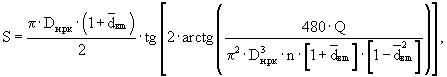
на торцевых поверхностях ее закреплены шайбы, изготовленные из антифрикционного износостойкого материала, а на боковой поверхности втулки по винтовой линии с шагом, равнымwashers made of anti-friction wear-resistant material are fixed on its end surfaces, and on the side surface of the sleeve along a helix with a step equal to

где 

где βл(ri) - угол наклона лопасти на радиусе ri;where β l (r i ) is the angle of inclination of the blade at a radius r i ;
S - шаг винтовой линии;S is the helix pitch;
ri - радиус, отсчитываемый от оси рабочего колеса до текущей точки на поверхности лопасти,r i is the radius measured from the axis of the impeller to the current point on the surface of the blade,
и густотой лопастной решетки на внешнем диаметре, обусловленной соотношениемand the density of the blade on the outer diameter, due to the ratio

где τн.рк - густота лопастной решетки рабочего колеса на внешнем диаметре;where τ n.rk is the density of the blade of the impeller on the outer diameter;
lн.рк - длина лопасти на внешнем диаметре;l N.rk - the length of the blade on the outer diameter;
zрк - число лопастей,z pk - the number of blades,
при этом статорный аппарат имеет втулку, в которой на торцевых поверхностях расположены бурты, а на боковой поверхности установлены радиально в направлении, параллельном оси ступени, лопатки со скругленными входными и выходными кромками, имеющими густоту лопаточной решетки на среднем диаметре, определяемую соотношениемwherein the stator apparatus has a sleeve in which collars are located on the end surfaces, and on the side surface are installed radially in the direction parallel to the axis of the step, the blades with rounded inlet and outlet edges having the density of the scapular lattice on the average diameter, determined by the ratio
![]()
![]()
где τcp.ca - густота лопаточной решетки статорного аппарата на среднем диаметре;where τ cp.ca is the density of the scapular lattice of the stator apparatus at an average diameter;
lса - длина лопатки;l CA — blade length;
zса - число лопаток;z CA - the number of blades;
Dcp.ca - средний диаметр лопатки статорного аппарата.D cp.ca is the average diameter of the stator vane.
За счет размещения с определенным шагом по винтовой линии на втулке рабочего колеса лопастей получаем простую конструкцию, которая имеет высокую технологичность изготовления осевого рабочего колеса, а также появляется возможность автоматизировать изготовление одной из самых массовых и трудоемких деталей рабочего колеса. Кроме того, появляется возможность увеличить число ступеней в насосе от нескольких десятков до нескольких сотен (400 и более), существенно повысив при этом напор насоса. Гидродинамическая характеристика винтовых лопастей позволяет в условиях ограниченных радиальных габаритов достигать в насосе высокой экономичности, составляющей в зависимости от сочетания его рабочих параметров 70-80%.Due to the placement of the blades with a certain pitch along the helix on the impeller bushing, we obtain a simple design, which has high manufacturability of the axial impeller manufacturing, and it also becomes possible to automate the production of one of the most massive and labor-intensive impeller parts. In addition, it becomes possible to increase the number of stages in the pump from several tens to several hundred (400 or more), while significantly increasing the pump head. The hydrodynamic characteristic of the screw blades allows in conditions of limited radial dimensions to achieve high efficiency in the pump, which, depending on the combination of its operating parameters, is 70-80%.
Колеса данной конструкции имеют высокий коэффициент реактивности (до 0,85), что позволяет упростить конструкцию статорного аппарата за счет отказа от выправляющей функции.The wheels of this design have a high coefficient of reactivity (up to 0.85), which allows to simplify the design of the stator apparatus due to the rejection of the straightening function.
Применение в статорном аппарате прямых радиальных лопаток позволяет осуществлять осевой подвод рабочей жидкости к рабочему колесу последующей ступени.The use of direct radial blades in the stator apparatus allows axial supply of working fluid to the impeller of the next stage.
Выполнение входных кромок лопастей рабочего колеса и лопаток статорного аппарата скругленными обеспечивает высокие энергетические качества колеса и аппарата за счет уменьшения вихревых потерь, которые неизбежно возникают при ударном натекании на входе с тыльной стороны лопастей и лопаток. Скругленные выходные кромки лопаток статорного аппарата при необходимой густоте лопастной решетки обеспечивают на выходе из аппарата и на входе в рабочее колесо последующей ступени эпюры полей скоростей в потоке рабочей жидкости, близкие к равномерным.The implementation of the input edges of the impeller blades and the stator blades rounded provides high energy qualities of the wheel and the apparatus by reducing the vortex losses that inevitably occur when impact leakage at the inlet from the back of the blades and blades. The rounded outlet edges of the blades of the stator apparatus with the required density of the blade array provide at the outlet of the apparatus and at the entrance to the impeller of the next stage of the velocity field diagram in the flow of working fluid close to uniform.
Наличие на торцевых поверхностях втулки рабочего колеса шайб, выполненных из износостойкого антифрикционного материала, и буртов на торцевых поверхностях втулки статорного аппарата позволяет осуществитьThe presence of washers on the end surfaces of the impeller sleeve made of wear-resistant antifriction material and collars on the end surfaces of the stator apparatus sleeve allows
разгрузку рабочего колеса от действия осевой силы без дополнительных гидравлических и с минимальными механическими потерями мощности в паре трения, доля которых в общем балансе энергии не превышает 5...8%.unloading of the impeller from the action of axial force without additional hydraulic and with minimal mechanical power losses in the friction pair, whose share in the total energy balance does not exceed 5 ... 8%.
Выбор величины втулочного отношения рабочего колеса по указанной зависимости обеспечивает получение максимально возможной экономичности насоса.The choice of the value of the impeller sleeve ratio according to the indicated dependence ensures obtaining the maximum possible pump efficiency.
Выбор шага винтовой линии по указанной зависимости обеспечивает совпадение расчетной подачи с оптимальной по к.п.д.The choice of the pitch of the helix according to the indicated dependence ensures the coincidence of the calculated feed with the optimal one in efficiency
За счет изменения длины и числа лопастей (лопаток) рабочего колеса (статорного аппарата) соответственно при сохранении густоты лопастной (лопаточной) решетки соответственно в указанном диапазоне возможно варьирование осевыми габаритами ступени, и, соответственно, напором насоса с заданной суммарной длиной сборки ступеней.By changing the length and number of the blades (blades) of the impeller (stator apparatus), respectively, while maintaining the density of the blade (scapular) grating, respectively, in the specified range, the axial dimensions of the stage and, accordingly, the pump head with a given total assembly length of the stages can be varied.
Использование совокупности всех существенных признаков, включая отличительные, позволяет повысить технологичность изготовления рабочих органов насоса, снизить трудоемкость изготовления, повысить экономичность и напор, увеличить надежность и долговечность работы насоса в нефтяной, нефтегазовой и горно-добывающей промышленности, в том числе, на газожидкостной смеси с высоким содержанием газа.The use of all the essential features, including distinctive features, makes it possible to increase the manufacturability of the pump working bodies, reduce the manufacturing complexity, increase the efficiency and pressure, increase the reliability and durability of the pump in the oil, oil and gas and mining industries, including gas-liquid mixtures with high gas content.
Изобретение поясняется чертежами.The invention is illustrated by drawings.
На фиг.1 схематически изображен предлагаемый многоступенчатый погружной осевой насос.Figure 1 schematically depicts the proposed multistage submersible axial pump.
На фиг.2 изображены рабочее колесо и статорный аппарат в аксонометрии.Figure 2 shows the impeller and the stator apparatus in a perspective view.
Многоступенчатый погружной осевой насос содержит входной модуль 1 (фиг.1) и от одной до пяти в зависимости от требуемого напора насоса модуль-секций 2 (фиг.1). Соединение модулей 2 между собой и входного модуля 1 насоса с электродвигателем - фланцевое. Уплотнение межмодульных соединений осуществляется резиновыми кольцами 3 (фиг.1). Соединение валов 4 (фиг.1) модуль-секций 2 между собой и вала 5 (фиг.1) входного модуля 2 с валом гидрозащиты двигателя осуществляется при помощи шлицевых муфт 6, 7 (фиг.1). В состав модуль-секций 2 входят: корпус 8 (фиг.1), пакет осевых ступеней, состоящий из рабочего колеса 9 (фиг.1, 2), статорного аппарата 10 (фиг.1, 2) и межступенчатой втулки 11 (фиг.1), а также верхнего и нижнего подшипников 12 и 13 (фиг.1), верхней осевой опоры 14 (фиг.1), головки 15 (фиг.1) и основания 16 (фиг.1). Соединение верхнего подшипника 12 с головкой 15 и корпусом 8, а также основания 16 с корпусом 8 - резьбовое, уплотненное резиновыми кольцами 17 (фиг.1). На каждом основании модуль-секций 2 установлено по два стальных ребра 18 (фиг.1), предназначенных для защиты плоского кабеля питания электродвигателя от механическихA multi-stage submersible axial pump contains an input module 1 (Fig. 1) and from one to five, depending on the required pump pressure of the module sections 2 (Fig. 1). The connection of the modules 2 to each other and the input module 1 of the pump with the electric motor is flange. The sealing of intermodular connections is carried out by rubber rings 3 (figure 1). The connection of the shafts 4 (figure 1) of the module sections 2 between themselves and the shaft 5 (figure 1) of the input module 2 with the shaft of the hydraulic protection of the engine is carried out using splined couplings 6, 7 (figure 1). The structure of the module sections 2 includes: a housing 8 (Fig. 1), a package of axial stages, consisting of an impeller 9 (Figs. 1, 2), a stator apparatus 10 (Figs. 1, 2) and an interstage sleeve 11 (Fig. 1), as well as the upper and lower bearings 12 and 13 (Fig. 1), the upper axial support 14 (Fig. 1), the head 15 (Fig. 1) and the base 16 (Fig. 1). The connection of the upper bearing 12 with the head 15 and the housing 8, as well as the base 16 with the housing 8 is threaded, sealed with rubber rings 17 (figure 1). On each base of the module sections 2, two steel ribs 18 are installed (Fig. 1), designed to protect the flat motor power cable from mechanical
повреждений о стенки обсадной трубы скважины при проведении спускоподъемных операций с погружным насосом. Корпус 19 (фиг.1) входного модуля 1, являющегося приемной частью насоса, имеет всасывающие отверстия 20 (фиг.1) и сетку (фильтр) 21 (фиг.1) для входа перекачиваемой среды. Вал входного корпуса имеет собственные радиальные опоры 22 (фиг.1). Рабочее колесо 9 (фиг.2) выполнено в виде втулки 23 (фиг.2) с закрепленными на ее торцевых поверхностях шайбами 24, 25 (фиг.2), изготовленными из антифрикционного износостойкого материала. На боковой поверхности втулки 23 по винтовой линии с постоянным шагом размещены лопасти 26 (фиг.2), входные кромки 27 (фиг.2) которых скруглены по радиусу, равному половине толщины лопасти. Статорный аппарат 10 (фиг.2) имеет втулку 28 (фиг.2), на торцевых поверхностях которой выполнены бурты 29, 30 (фиг.2), а на боковой поверхности размещены радиально установленные лопатки 31 (фиг.2), входная 32 (фиг.2) и выходная кромки 33 (фиг.2), которые также закруглены по радиусу, равному половине толщины лопатки.damage to the walls of the casing of the well during tripping operations with a submersible pump. The housing 19 (Fig. 1) of the input module 1, which is the receiving part of the pump, has suction holes 20 (Fig. 1) and a mesh (filter) 21 (Fig. 1) for the inlet of the pumped medium. The shaft of the input housing has its own radial bearings 22 (figure 1). The impeller 9 (figure 2) is made in the form of a sleeve 23 (figure 2) with
Насос работает следующим образом. Перекачиваемая среда, обтекая лопасти 26 рабочего колеса, повышает свой напор за счет ударного натекания на их входные кромки 27. Выходящий из рабочих колес 9 поток перекачиваемой среды раскручивается в статорных аппаратах 10 и входит в рабочие колеса последующих ступеней осевым.The pump operates as follows. The pumped medium, flowing around the
Осевая сила, действующая на рабочие колеса на установившихся режимах работы, воспринимается нижней индивидуальной торцовой опорой, состоящей из шайбы 24 и бурта 29. В период пусков и остановок, а также при работе на расходах, превышающих оптимальный по к.п.д., осевая нагрузка на рабочие колеса может уменьшиться до нуля, а затем изменить направление на противоположное. При этом рабочие колеса всплывают и работают на верхней индивидуальной торцевой опоре, состоящей из шайбы 25 и бурта 30. Остаточное осевое усилие на роторы модуль-секций воспринимает имеющаяся в каждом из них верхняя осевая опора 14. Радиальные усилия, действующие на ротор, воспринимаются верхним 12 и нижним 13 подшипниками на концах валов модуль-секций, а также радиальными подшипниками 34, установленными в каждом статорном аппарате.The axial force acting on the impellers in steady-state operating modes is perceived by the lower individual end support, consisting of a
Использование предлагаемой конструкции насоса имеет по сравнению с существующими следующие преимущества:Using the proposed pump design has the following advantages over existing ones:
- повышается технологичность изготовления и снижается трудоемкость;- increases the manufacturability and reduces the complexity;
- обеспечивается возможность автоматизации процесса;- provides the ability to automate the process;
- повышаются напорность и экономичность;- pressure and profitability increase;
- повышаются надежность и долговечность;- increased reliability and durability;
- обеспечивается возможность широкого использования в нефтяной, нефтегазовой и горно-добывающей промышленности с высоким т.э.п.- provides the possibility of widespread use in the oil, oil and gas and mining industries with high TPE
Claims (1)


Applications Claiming Priority (2)
| Application Number | Priority Date | Filing Date | Title |
|---|---|---|---|
| UA2002065305 | 2002-06-27 | ||
| UA2002065305 | 2002-06-27 |
Publications (2)
| Publication Number | Publication Date |
|---|---|
| RU2003116144A RU2003116144A (en) | 2004-11-20 |
| RU2244164C1 true RU2244164C1 (en) | 2005-01-10 |
Family
ID=34421072
Family Applications (1)
| Application Number | Title | Priority Date | Filing Date |
|---|---|---|---|
| RU2003116144/06A RU2244164C1 (en) | 2002-06-27 | 2003-06-02 | Multistage submerged axial pump |
Country Status (2)
| Country | Link |
|---|---|
| US (1) | US20040096320A1 (en) |
| RU (1) | RU2244164C1 (en) |
Cited By (2)
| Publication number | Priority date | Publication date | Assignee | Title |
|---|---|---|---|---|
| RU2516753C1 (en) * | 2012-10-04 | 2014-05-20 | Закрытое Акционерное Общество "Новомет-Пермь" | Submersible pump for viscous fluid pumping |
| RU203924U1 (en) * | 2020-12-16 | 2021-04-28 | федеральное государственное автономное образовательное учреждение высшего образования "Российский государственный университет нефти и газа (национальный исследовательский университет) имени И.М. Губкина" | PUMP |
Families Citing this family (10)
| Publication number | Priority date | Publication date | Assignee | Title |
|---|---|---|---|---|
| US20050267799A1 (en) * | 2004-05-10 | 2005-12-01 | Wesley Chan | System and method for enabling publishers to select preferred types of electronic documents |
| EP2339110A1 (en) * | 2009-12-23 | 2011-06-29 | Welltec A/S | Downhole tool for borehole cleaning or for moving fluid in a borehole |
| US8568081B2 (en) | 2010-04-20 | 2013-10-29 | Baker Hughes Incorporated | Axial thrust balanced impeller for use with a downhole electrical submersible pump |
| CN103411465A (en) * | 2013-08-27 | 2013-11-27 | 北京化工大学 | Penetration type concave-convex blade rotor inside heat exchange pipe |
| US11933323B2 (en) | 2015-07-23 | 2024-03-19 | Onesubsea Ip Uk Limited | Short impeller for a turbomachine |
| US10876536B2 (en) | 2015-07-23 | 2020-12-29 | Onesubsea Ip Uk Limited | Surge free subsea compressor |
| EP3379083B1 (en) * | 2017-03-21 | 2023-08-23 | OneSubsea IP UK Limited | Short impeller for a turbomachine |
| CN107165852A (en) * | 2017-06-29 | 2017-09-15 | 吉林市奥吉通泵业有限责任公司 | A kind of high intensity is modified the enhanced embedded-type modularized immersible pump of polyformaldehyde composite material |
| CN110671335B (en) * | 2019-09-23 | 2020-11-20 | 江苏大学 | Multi-stage high-temperature pump with disrotatory structure |
| US11867176B1 (en) | 2021-04-16 | 2024-01-09 | Lex Submersible Pumps FZE Company | Method and apparatus for a submersible multistage labyrinth-screw pump |
Family Cites Families (2)
| Publication number | Priority date | Publication date | Assignee | Title |
|---|---|---|---|---|
| AT359941B (en) * | 1979-01-18 | 1980-12-10 | Buchelt Benno | WATER TURBINE |
| US4280792A (en) * | 1979-02-09 | 1981-07-28 | Avco Corporation | Air-cooled turbine rotor shroud with restraints |
-
2003
- 2003-06-02 RU RU2003116144/06A patent/RU2244164C1/en not_active IP Right Cessation
- 2003-06-26 US US10/607,686 patent/US20040096320A1/en not_active Abandoned
Non-Patent Citations (1)
| Title |
|---|
| ЛОМАКИН А.А. Центробежные и осевые насосы. - М.-Л., 1966, с.346, 347, рис.235. * |
Cited By (2)
| Publication number | Priority date | Publication date | Assignee | Title |
|---|---|---|---|---|
| RU2516753C1 (en) * | 2012-10-04 | 2014-05-20 | Закрытое Акционерное Общество "Новомет-Пермь" | Submersible pump for viscous fluid pumping |
| RU203924U1 (en) * | 2020-12-16 | 2021-04-28 | федеральное государственное автономное образовательное учреждение высшего образования "Российский государственный университет нефти и газа (национальный исследовательский университет) имени И.М. Губкина" | PUMP |
Also Published As
| Publication number | Publication date |
|---|---|
| US20040096320A1 (en) | 2004-05-20 |
Similar Documents
| Publication | Publication Date | Title |
|---|---|---|
| CA2419458C (en) | Electric submersible pump with specialized geometry for pumping viscous crude oil | |
| US8070426B2 (en) | System, method and apparatus for open impeller and diffuser assembly for multi-stage submersible pump | |
| RU2244164C1 (en) | Multistage submerged axial pump | |
| RU2563406C2 (en) | Turbine plant for energy supply to multi-phase fluid (versions) and method of energy supply to multi-phase fluid | |
| CA2806472C (en) | Pump/motor assembly | |
| RU2472039C1 (en) | Structural row of vertical electrically driven oil pumps | |
| CN105351206A (en) | Segmentation type multi-stage centrifugal pump | |
| CN105526194B (en) | Adjustable vane device and sectional multi-stage centrifugal pump | |
| CN205371092U (en) | Adjustable vane device and festival segmentation multistage centrifugal pump | |
| RU2368812C1 (en) | Deep-well multiphase pump | |
| US7150600B1 (en) | Downhole turbomachines for handling two-phase flow | |
| RU63468U1 (en) | STEP OF SUBMERSIBLE MULTISTAGE CENTRIFUGAL PUMP | |
| RU2435075C2 (en) | Pumping unit and pumping system in which it is used | |
| RU59752U1 (en) | STEP OF SUBMERSIBLE MULTISTAGE CENTRIFUGAL PUMP | |
| RU2093710C1 (en) | Centrifugal modular submersible pump | |
| RU74174U1 (en) | STEP OF SUBMERSIBLE MULTISTAGE CENTRIFUGAL PUMP | |
| CN101403387A (en) | Helical axial flow type multiphase pump supercharging unit | |
| RU2249728C2 (en) | Centrifugal multistage pump | |
| RU61812U1 (en) | SUBMERSIBLE CENTRIFUGAL PUMP DISPERSANT | |
| RU119823U1 (en) | MULTI-STAGE CENTRIFUGAL PUMP | |
| RU66444U1 (en) | SUBMERSIBLE MULTI-STAGE CENTRIFUGAL PUMP | |
| RU2269032C2 (en) | Stage of submersible multistage centrifugal pump | |
| RU70324U1 (en) | HIGH-TURNING SUBMERSIBLE MULTI-PHASE PUMP | |
| RU2285103C1 (en) | Turbodrill | |
| RU66789U1 (en) | PUMP DISPERSANT |
Legal Events
| Date | Code | Title | Description |
|---|---|---|---|
| MM4A | The patent is invalid due to non-payment of fees |
Effective date: 20050603 |