RU2215840C1 - Modular block of front mechanisms for sewing machine - Google Patents
Modular block of front mechanisms for sewing machine Download PDFInfo
- Publication number
- RU2215840C1 RU2215840C1 RU2002118789/12A RU2002118789A RU2215840C1 RU 2215840 C1 RU2215840 C1 RU 2215840C1 RU 2002118789/12 A RU2002118789/12 A RU 2002118789/12A RU 2002118789 A RU2002118789 A RU 2002118789A RU 2215840 C1 RU2215840 C1 RU 2215840C1
- Authority
- RU
- Russia
- Prior art keywords
- frame
- block module
- needle bar
- block
- serves
- Prior art date
Links
- 238000009958 sewing Methods 0.000 title claims abstract description 14
- 230000007246 mechanism Effects 0.000 title claims description 13
- 229920003023 plastic Polymers 0.000 claims description 2
- 239000004033 plastic Substances 0.000 claims description 2
- 238000010276 construction Methods 0.000 abstract 1
- 230000000694 effects Effects 0.000 abstract 1
- 230000001105 regulatory effect Effects 0.000 abstract 1
- 239000000126 substance Substances 0.000 abstract 1
- 238000009434 installation Methods 0.000 description 3
- 238000005266 casting Methods 0.000 description 2
- 238000004519 manufacturing process Methods 0.000 description 2
- 239000000463 material Substances 0.000 description 2
- 229910000838 Al alloy Inorganic materials 0.000 description 1
- 239000004698 Polyethylene Substances 0.000 description 1
- 230000033228 biological regulation Effects 0.000 description 1
- 230000015572 biosynthetic process Effects 0.000 description 1
- 230000007423 decrease Effects 0.000 description 1
- 230000005489 elastic deformation Effects 0.000 description 1
- 230000008030 elimination Effects 0.000 description 1
- 238000003379 elimination reaction Methods 0.000 description 1
- 238000000034 method Methods 0.000 description 1
- -1 polyethylene Polymers 0.000 description 1
- 229920000573 polyethylene Polymers 0.000 description 1
Images


Landscapes
- Sewing Machines And Sewing (AREA)
Abstract
Description
Изобретение относится к швейному машиностроению и более конкретно к бытовым швейным машинам зигзаг, в которых предварительно собранный блок устанавливается или монтируется во фронтальной части машины на заранее подготовленное место с последующей и соответствующей регулировкой при монтаже, при условии, что рамка качания игловодителя, применяемая в блок-модуле, качается на верхней оси и относится к рамкам маятникового типа. The invention relates to sewing machine-building and more specifically to domestic zigzag sewing machines in which a pre-assembled unit is mounted or mounted in the front of the machine at a pre-prepared place with subsequent and appropriate adjustment during installation, provided that the needle bar swing frame used in the unit module, swinging on the upper axis and refers to the framework of the pendulum type.
Известна швейная машина (1), в которой блок-модуль с фронтальными механизмами - рамкой качания игловодителя, механизмом лапки - располагаются на отдельном корпусе (раме), который прикрепляется к корпусу машины (головке) с возможностью регулирования иглы относительно паза игольной пластины. Known sewing machine (1), in which a block module with frontal mechanisms - the needle bar swing frame, the mechanism of the legs - are located on a separate case (frame), which is attached to the machine body (head) with the ability to adjust the needle relative to the groove of the needle plate.
К недостаткам данной конструкции следует отнести большую материалоемкость корпуса блока, который включает угловую пластину, прикрепленную с возможностью регулирования к головке машины, и несущую рамку качания игловодителя, и стержень лапки, установленный в верхней и нижней направляющих втулках. The disadvantages of this design include the large material consumption of the block body, which includes an angular plate attached with the possibility of regulation to the head of the machine, and the bearing frame of the needle bar, and the bar paw mounted in the upper and lower guide bushings.
Известна швейная машина (2), в которой корпус блока фронтальных механизмов имеет ось для качания рамки игловодителя с верхней и нижней опорами для возвратно-поступательного перемещения игловодителя, подпружиненный стержень лапки, установленный в верхней и нижней опорах и снабженный поводком для рычага подъема лапки. Блок-модуль снабжен опорами для его установки в корпусе (головке) швейной машины. Опоры позволяют производить регулировку иглы вдоль и поперек линии строчки. A sewing machine is known (2), in which the case of the block of frontal mechanisms has an axis for swinging the needle bar frame with upper and lower supports for reciprocating movement of the needle bar, a spring-loaded paw bar installed in the upper and lower supports and equipped with a leash for the lever for raising the presser foot. The block module is equipped with supports for its installation in the body (head) of the sewing machine. The supports allow you to adjust the needle along and across the stitch line.
Стержень лапки выполнен в виде пластины, установленной посредством пазов на шпильках, при этом пазы выполнены со смещением относительно друг друга, а пружина расположена на плече пластины, создавая момент силы, действующий на шпильку. Сама пластина является тяжелой, материалоемкой, сложна в изготовлении, в т.ч. и из-за наличия пазов для перемещения в вертикальной плоскости, параллельность которых должна быть достаточно точной. The foot of the foot is made in the form of a plate mounted by means of grooves on the studs, while the grooves are displaced relative to each other, and the spring is located on the shoulder of the plate, creating a moment of force acting on the stud. The plate itself is heavy, material-intensive, difficult to manufacture, including and due to the presence of grooves for movement in a vertical plane, the parallelism of which must be sufficiently accurate.
Техническим результатом изобретения является устранение указанных недостатков и создание такого блока-модуля, в котором корпус одновременно служит опорой стержня лапки. The technical result of the invention is the elimination of these disadvantages and the creation of such a block module, in which the housing simultaneously serves as a support for the foot shaft.
Указанный технический результат достигается тем, что в блоке-модуле фронтальных механизмов швейной машины, содержащим корпус, несущий ось качания рамки игловодителя, корпус рамки которой имеет верхнюю и нижнюю опоры для возвратно-поступательного перемещения игловодителя, подпружиненный стержень лапки, установленный в верхней и нижней опорах и снабженный поводком для рычага подъема лапки, опоры для установки блок-модуля во фронтовой части рукава машины, верхняя и нижняя опоры стержня лапки выполнены в виде сферических втулок, смонтированных в разъемных подшипниках, основаниями которых служит корпус блок-модуля, при этом крышка верхнего подшипника снабжена сферической втулкой и служит верхней опорой игловодителя, а крышка нижнего подшипника служит в качестве направляющей рамки игловодителя, ось которой закреплена на крышке верхнего подшипника. The specified technical result is achieved by the fact that in the block module of the front mechanisms of the sewing machine, comprising a housing bearing a swing axis of the needle bar frame, the frame body of which has an upper and lower support for reciprocating movement of the needle bar, a spring-loaded pin bar mounted in the upper and lower supports and equipped with a leash for the lever for raising the presser foot, supports for mounting the block module in the front of the machine arm, the upper and lower supports of the presser foot are made in the form of spherical bushings, mounted OF DATA in split bearings bases which serves as the housing block module, the upper cover is provided with a spherical bearing sleeve and serves as the upper support of the needle bar, and the lower bearing cover serves as a guide needle bar frame, the axis of which is fixed to the top bearing cover.
Кроме того, одна из опор для установки блока-модуля во фронтовой части рукава машины выполнена в виде призматической направляющей. In addition, one of the supports for installing the block module in the front of the machine sleeve is made in the form of a prismatic guide.
Анализ известных технических решений в исследуемой области позволяет сделать вывод об отсутствии в них признаков, сходных с существенными отличительными признаками в заявляемом блоке, и признать заявляемое решение, соответствующим критерию "изобретательский уровень". An analysis of the known technical solutions in the study area allows us to conclude that they lack features similar to the essential distinguishing features in the claimed unit and recognize the claimed solution that meets the criterion of "inventive step".
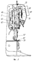
На фиг.1 изображена швейная машина с блок-модулем, вид спереди, передняя крышка снята;
На фиг.2 - вид с фронта швейной машины с блок-модулем;
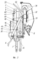
На фиг.3 - вид с фронта блок-модуля;
На фиг.4 - вид спереди блок модуля;
На фиг.5 - разрез по А-А на фиг.4;
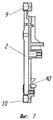
На фиг.6 - корпус блок-модуля;
На фиг.7 - разрез по Б-Б на фиг.6;
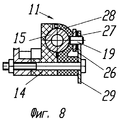
На фиг. 8 - вариант исполнения крышки верхнего разъемного подшипника стержня лапки.Figure 1 shows a sewing machine with a block module, front view, the front cover is removed;
Figure 2 is a front view of a sewing machine with a block module;
Figure 3 is a view from the front of the block module;
Figure 4 is a front view of the module block;
Figure 5 is a section along aa in figure 4;
Figure 6 - the housing of the block module;
Fig.7 is a section along BB in Fig.6;
In FIG. 8 is an embodiment of a cap of an upper releasable bearing of a bar of a foot.
Блок-модуль 1 фронтальных механизмов швейной машины содержит корпус блока 2, который в верхней части содержит призматический паз 3. Посредством последнего блок-модуль монтируется на оси 4 нитепритягивателя. The block module 1 of the front mechanisms of the sewing machine contains a
На корпусе 2 смонтирована рамка 5 качания игловодителя, рычаг 6 ручного подъема лапки. В корпусе 2 установлен стержень 7 лапки, подпружиненный пружиной 8. A
Корпус блока 2 представляет собой отливку, выполненную, например, из алюминиевого сплава и служащую основанием 9 и 10 соответственно для разъемных подшипников: верхнего 11 и нижнего 12.
Внутри указанных подшипников размещены сферические втулки 13, которые служат направляющими втулками или опорами для подпружиненного стержня 7 лапки.
В крышке 14 верхнего разъемного подшипника смонтирована сферическая втулка 15, которая служит верхней опорой игловодителя 16, нижняя опора последнего также выполнена в виде сферической втулки 17, которая установлена в нижней съемной полке 18 рамки 5 качания игловодителя. Рамка 5 маятникового типа и в верхней части установлена на оси 19, закрепленной на крышке 14 верхнего 11 разъемного подшипника. A
Таким образом, крышка 14 служит верхней полкой игловодителя, но поскольку она выполнена неподвижной, поворот (качание) игловодителя в верхней опоре обеспечивается за счет поворота сферической втулки 15 в крышке 14. Thus, the
Нижняя съемная полка 18 выполнена в виде разъемного подшипника 20, основание 21 которого контактирует с крышкой 22 нижнего 12 разъемного подшипника, т.е. последняя служит в качестве направляющей рамки 5 игловодителя. The lower
Крышка 23 разъемного подшипника 20 снабжена выступом 24, на который посредством отверстия 25 одета пластина 26. Последняя служит корпусом рамки 5 и к ней посредством винтов прикреплена нижняя съемная полка 18. Верхним отверстием 27 пластина 26 одета на упомянутую ось 19. The
Таким образом, игловодитель 16 в рамке 5 качания перемещается возвратно-поступательно в сферических втулках 15 и 17, которые и служат опорами игловодителя, а качание рамки 5 игловодителя поперек линии строчки осуществлено посредством подвешивания ее на оси 19 и поворота сферической втулки 15 в крышке 14 верхнего разъемного подшипника 11. Ось качания рамки и геометрическая ось сферической втулки 15 совпадают. Thus, the
Сферическая втулка 15 вводится в посадочное место на верхней полке или, что то же самое, в крышке 14 путем проталкивания благодаря повышенной способности к упругой деформации материала, из которого выполнена крышка 14, например полиэтилена. The
В варианте исполнения верхняя опора игловодителя - сферическая втулка 15 может быть установлена в разъемном подшипнике, представленным основанием, в качестве которого служит крышка 14 верхнего 11 разъемного подшипника стержня лапки, и крышкой 28, несущую упомянутую ось 19. На последнюю, как и в первом случае, посредством отверстия 27 одета пластина 26 для качания рамки 5 игловодителя. Также рамка 5 может быть снабжена дополнительной опорой 29, прикрепленной к корпусу блока, в отверстие которой входит упомянутая ось 19. На дополнительной опоре 29 смонтирован также регулятор натяжения верхней нитки 30. In an embodiment, the needle bar's upper support — a spherical bushing 15 — can be mounted in a separable bearing, represented by a base, which is the
Регулятор состоит из шарнирно установленной рукоятки 31 с цифровой индикацией и спиралевидным кулачком 32, взаимодействующим с плоской фигурной пружиной 33, верхним концом надетой на шпиндель 34 и взаимодействующей с шайбами натяжения 35 через втулку освобождения 36, надетой также на шпиндель 34. The controller consists of a pivotally mounted
Нижний конец пружины взаимодействует с упором 37. При повороте рукоятки по часовой или против часовой стрелки кулачок 32 взаимодействует с пружиной 33 и тем самым увеличивает или уменьшает давление на шайбы натяжения 35. The lower end of the spring interacts with the
Рычаг 6 ручного подъема стержня лапки имеет верхнюю поверхность 38. Ось 39 рычага 6 установлена в призматических направляющих 40, а рычаг подпружинен фигурной пружиной 41, закрепленной на корпусе винтом 42. The
Верхняя поверхность 38 рычага 6 ручного подъема взаимодействует с поводком 43, который закреплен на стержне 7 лапки. Свободный конец поводка находится в направляющем пазу 44 пластины 45, прикрепленной к корпусу блока 2 посредством винта 46. The
Для подъема стержня 7 лапки необходимо повернуть рычаг 6, который, преодолевая усилие пружины 8, поднимает стержень 7, а вместе с ним и лапку 47. To raise the bar 7 of the foot, it is necessary to turn the
Блок-модуль также несет устройство 48 освобождения натяжения верхней нитки. Оно выполнено в виде штанги 49, нижним концом шарнирно соединенным с рычагом 6 подъема, а верхним взаимодействующим с колпачком освобождения посредством вилки 50, которой она охватывает буртик на втулке 36. The block module also carries an upper thread
Штанга 49 в верхней части снабжена выступом 51, взаимодействующим при подъеме рычага 6 ручного подъема лапки с отводчиком штанги, выполненным в виде пальца 52, закрепленным на дополнительной опоре 29. The
При подъеме рычага 6 ручного подъема лапки штанга 49, поднимаясь, выступом 51 взаимодействует с пальцем 52. В результате верхняя часть штанги, т. е. вилка 50, взаимодействует с втулкой освобождения 36 и, преодолевая усилие верхнего конца пружины 33, освобождает шайбы натяжения 35. When raising the
На штанге 49 закреплен нитенаправитель 53, который удерживает верхнюю нитку в процессе пошива, благодаря чему обеспечивается больший угол охвата ниткой стержня между шайбами, т.е. нитка зажимается на большей длине и, как следствие, улучшается процесс стежкообразования. A
Нитка располагается под изогнутой частью нитенаправителя. Средство крепления нитенаправителя выполняет роль выступа 51 на штанге 49. The thread is located under the curved part of the thread guide. The thread guide attachment acts as a protrusion 51 on the
Таким образом, в собранном виде блок-модуль содержит механизм лапки, включающий подпружиненный стержень 7 лапки, рычаг 6 ручного подъема лапки, механизм иглы, включающий рамку 5 качания игловодителя, игловодитель с поводком 54, регулятор 30 натяжения верхней нитки, устройство 48 освобождения натяжения верхней нитки, нитенаправитель 53. Thus, in assembled form, the block module comprises a presser foot mechanism including a spring-loaded presser foot shaft 7, a
Все указанные элементы смонтированы на корпусе блока 2. В таком виде блок-модуль монтируется посредством верхнего призматического паза 3 во фронтальной части 55 рукава 56 машины. All these elements are mounted on the housing of the
Паз 3 позволяет регулировать блок вдоль и поперек строчки, т.е. регулировать положение иглы 57 относительно паза 58 игольной пластины 59 в продольном и поперечном направлениях. Groove 3 allows you to adjust the block along and across the stitch, i.e. adjust the position of the
Достигается это посредством продвижения блок-модуля 1 по оси 4 и поворотом его вокруг указанной оси. Крепление к оси 4 осуществляется посредством прижима 60 и болта 61, ввернутого в корпус блока 2. This is achieved by advancing the block module 1 on axis 4 and rotating it about the specified axis. The fastening to the axis 4 is carried out by means of a
После требуемой установки блок-модуля по отношению к пазу 58 игольной пластины 59 болтом 61 закрепляют прижим 60. Окончательное крепление блок-модуля достигается подводной опорой, выполненной в виде контактирующего с рукавом 56 машины винта 62, ввернутого в корпус блока 2, и фиксирующего винта 63, установленного в отверстии 64, выполненном с ощутимым зазором в корпусе блока 2. Благодаря чему регулировка и юстировка блок-модуля просты и надежны. After the required installation of the block module in relation to the groove 58 of the needle plate 59, the
При этом призматический паз в корпусе блока 2 выполнен при литье корпуса и дальнейшей обработки не требует. In this case, the prismatic groove in the casing of the
Также не требуют дальнейшей обработки и посадочные места, служащие основанием 9 и 10 в корпусе блока, соответственно верхнего 11 и нижнего 12 разъемных подшипников для стержня 7 лапки. Also, no further processing is required for the seats serving as the
Не требуют дальнейшей обработки и крышки 14 и 22 указанных разъемных подшипников, поскольку они выполняются литьем из пластмассы. Do not require further processing and covers 14 and 22 of these separable bearings, since they are molded from plastic.
В целом предлагаемая конструкция блок-модуля компактна, менее трудоемка в изготовлении, удобна в юстировке. In general, the proposed design of the block module is compact, less laborious to manufacture, and convenient to align.
Источники информации
1. Европейский патент 0939159, D 04 B 73/02.Sources of information
1. European patent 0939159, D 04 B 73/02.
2. Патент США 4044701, кл. США 112-259.7 2. US patent 4044701, CL US 112-259.7
Claims (5)
Priority Applications (2)
| Application Number | Priority Date | Filing Date | Title |
|---|---|---|---|
| RU2002118789/12A RU2215840C1 (en) | 2002-07-17 | 2002-07-17 | Modular block of front mechanisms for sewing machine |
| EA200300592A EA005359B1 (en) | 2002-07-17 | 2003-06-05 | Block-module of sewing machine frontal mechanisms |
Applications Claiming Priority (1)
| Application Number | Priority Date | Filing Date | Title |
|---|---|---|---|
| RU2002118789/12A RU2215840C1 (en) | 2002-07-17 | 2002-07-17 | Modular block of front mechanisms for sewing machine |
Publications (1)
| Publication Number | Publication Date |
|---|---|
| RU2215840C1 true RU2215840C1 (en) | 2003-11-10 |
Family
ID=32028103
Family Applications (1)
| Application Number | Title | Priority Date | Filing Date |
|---|---|---|---|
| RU2002118789/12A RU2215840C1 (en) | 2002-07-17 | 2002-07-17 | Modular block of front mechanisms for sewing machine |
Country Status (2)
| Country | Link |
|---|---|
| EA (1) | EA005359B1 (en) |
| RU (1) | RU2215840C1 (en) |
Citations (5)
| Publication number | Priority date | Publication date | Assignee | Title |
|---|---|---|---|---|
| US4044701A (en) * | 1973-03-16 | 1977-08-30 | Husqvarna Aktiebolag | Sewing machine frame with presser foot and needle bar unit |
| DE3421995A1 (en) * | 1983-06-22 | 1985-01-10 | The Singer Co., Stamford, Conn. | SEWING MACHINE HEAD PART IN MODULAR DESIGN |
| RU2055960C1 (en) * | 1992-04-20 | 1996-03-10 | Конструкторское бюро приборостроения | Needle guide mechanism of zigzag sewing machine |
| EP0939159A1 (en) * | 1998-02-27 | 1999-09-01 | Fritz Gegauf Ag Bernina-Nähmaschinenfabrik | Sewing machine with an adjustable head unit |
| RU2151225C1 (en) * | 1999-02-16 | 2000-06-20 | Умяров Равиль Константинович | Zigzag sewing machine |
Family Cites Families (1)
| Publication number | Priority date | Publication date | Assignee | Title |
|---|---|---|---|---|
| CH676999A5 (en) * | 1988-11-30 | 1991-03-28 | Mefina Sa |
-
2002
- 2002-07-17 RU RU2002118789/12A patent/RU2215840C1/en not_active IP Right Cessation
-
2003
- 2003-06-05 EA EA200300592A patent/EA005359B1/en not_active IP Right Cessation
Patent Citations (5)
| Publication number | Priority date | Publication date | Assignee | Title |
|---|---|---|---|---|
| US4044701A (en) * | 1973-03-16 | 1977-08-30 | Husqvarna Aktiebolag | Sewing machine frame with presser foot and needle bar unit |
| DE3421995A1 (en) * | 1983-06-22 | 1985-01-10 | The Singer Co., Stamford, Conn. | SEWING MACHINE HEAD PART IN MODULAR DESIGN |
| RU2055960C1 (en) * | 1992-04-20 | 1996-03-10 | Конструкторское бюро приборостроения | Needle guide mechanism of zigzag sewing machine |
| EP0939159A1 (en) * | 1998-02-27 | 1999-09-01 | Fritz Gegauf Ag Bernina-Nähmaschinenfabrik | Sewing machine with an adjustable head unit |
| RU2151225C1 (en) * | 1999-02-16 | 2000-06-20 | Умяров Равиль Константинович | Zigzag sewing machine |
Also Published As
| Publication number | Publication date |
|---|---|
| EA005359B1 (en) | 2005-02-24 |
| EA200300592A1 (en) | 2004-02-26 |
Similar Documents
| Publication | Publication Date | Title |
|---|---|---|
| JPH05277274A (en) | Sewing machine device | |
| JPS632393Y2 (en) | ||
| JP2003177741A (en) | Tremolo device for electric guitar, and electric guitar | |
| RU2215840C1 (en) | Modular block of front mechanisms for sewing machine | |
| US3420200A (en) | Modular sewing machines | |
| US4552081A (en) | Skeletal frame sewing machine | |
| US9340911B2 (en) | Sewing machine | |
| JPH0429400B2 (en) | ||
| JPS63283692A (en) | Sewing machine | |
| JP5050493B2 (en) | Sewing machine threading device | |
| RU2215838C1 (en) | Zigzag-type sewing machine | |
| JPH075821Y2 (en) | sewing machine | |
| US2730979A (en) | Sewing machine | |
| RU2202017C1 (en) | Needle thread tension regulator for sewing machine | |
| JP3104037U (en) | Opener device for cylindrical sewing machine | |
| JPH0325744Y2 (en) | ||
| RU22667U1 (en) | DEVICE FOR WINDING THREAD ON SEXUAL SHUTTER HOSE | |
| JP2003326005A (en) | Needle feed sewing machine | |
| JPH0223253Y2 (en) | ||
| JP2696838B2 (en) | Sky bottle mechanism of sewing machine | |
| JPH0314149Y2 (en) | ||
| JPS5927907Y2 (en) | Sewing machine needle bar movement control device | |
| JPH0323175Y2 (en) | ||
| US4535710A (en) | Stabilizing arrangement for a sewing machine cam post | |
| JP2696836B2 (en) | sewing machine |
Legal Events
| Date | Code | Title | Description |
|---|---|---|---|
| MM4A | The patent is invalid due to non-payment of fees |
Effective date: 20060718 |