RU2205705C2 - Liquid sprayer and nozzle insert - Google Patents
Liquid sprayer and nozzle insert Download PDFInfo
- Publication number
- RU2205705C2 RU2205705C2 RU2000124400/12A RU2000124400A RU2205705C2 RU 2205705 C2 RU2205705 C2 RU 2205705C2 RU 2000124400/12 A RU2000124400/12 A RU 2000124400/12A RU 2000124400 A RU2000124400 A RU 2000124400A RU 2205705 C2 RU2205705 C2 RU 2205705C2
- Authority
- RU
- Russia
- Prior art keywords
- venturi
- product
- propellant
- outlet
- container
- Prior art date
Links
Images


Classifications
-
- B—PERFORMING OPERATIONS; TRANSPORTING
- B05—SPRAYING OR ATOMISING IN GENERAL; APPLYING FLUENT MATERIALS TO SURFACES, IN GENERAL
- B05B—SPRAYING APPARATUS; ATOMISING APPARATUS; NOZZLES
- B05B7/00—Spraying apparatus for discharge of liquids or other fluent materials from two or more sources, e.g. of liquid and air, of powder and gas
- B05B7/24—Spraying apparatus for discharge of liquids or other fluent materials from two or more sources, e.g. of liquid and air, of powder and gas with means, e.g. a container, for supplying liquid or other fluent material to a discharge device
- B05B7/26—Apparatus in which liquids or other fluent materials from different sources are brought together before entering the discharge device
- B05B7/28—Apparatus in which liquids or other fluent materials from different sources are brought together before entering the discharge device in which one liquid or other fluent material is fed or drawn through an orifice into a stream of a carrying fluid
- B05B7/30—Apparatus in which liquids or other fluent materials from different sources are brought together before entering the discharge device in which one liquid or other fluent material is fed or drawn through an orifice into a stream of a carrying fluid the first liquid or other fluent material being fed by gravity, or sucked into the carrying fluid
-
- B—PERFORMING OPERATIONS; TRANSPORTING
- B65—CONVEYING; PACKING; STORING; HANDLING THIN OR FILAMENTARY MATERIAL
- B65D—CONTAINERS FOR STORAGE OR TRANSPORT OF ARTICLES OR MATERIALS, e.g. BAGS, BARRELS, BOTTLES, BOXES, CANS, CARTONS, CRATES, DRUMS, JARS, TANKS, HOPPERS, FORWARDING CONTAINERS; ACCESSORIES, CLOSURES, OR FITTINGS THEREFOR; PACKAGING ELEMENTS; PACKAGES
- B65D83/00—Containers or packages with special means for dispensing contents
- B65D83/14—Containers or packages with special means for dispensing contents for delivery of liquid or semi-liquid contents by internal gaseous pressure, i.e. aerosol containers comprising propellant for a product delivered by a propellant
- B65D83/60—Contents and propellant separated
-
- B—PERFORMING OPERATIONS; TRANSPORTING
- B05—SPRAYING OR ATOMISING IN GENERAL; APPLYING FLUENT MATERIALS TO SURFACES, IN GENERAL
- B05B—SPRAYING APPARATUS; ATOMISING APPARATUS; NOZZLES
- B05B7/00—Spraying apparatus for discharge of liquids or other fluent materials from two or more sources, e.g. of liquid and air, of powder and gas
- B05B7/02—Spray pistols; Apparatus for discharge
- B05B7/04—Spray pistols; Apparatus for discharge with arrangements for mixing liquids or other fluent materials before discharge
- B05B7/0416—Spray pistols; Apparatus for discharge with arrangements for mixing liquids or other fluent materials before discharge with arrangements for mixing one gas and one liquid
- B05B7/0433—Spray pistols; Apparatus for discharge with arrangements for mixing liquids or other fluent materials before discharge with arrangements for mixing one gas and one liquid with one inner conduit of gas surrounded by an external conduit of liquid upstream the mixing chamber
-
- B—PERFORMING OPERATIONS; TRANSPORTING
- B05—SPRAYING OR ATOMISING IN GENERAL; APPLYING FLUENT MATERIALS TO SURFACES, IN GENERAL
- B05B—SPRAYING APPARATUS; ATOMISING APPARATUS; NOZZLES
- B05B7/00—Spraying apparatus for discharge of liquids or other fluent materials from two or more sources, e.g. of liquid and air, of powder and gas
- B05B7/24—Spraying apparatus for discharge of liquids or other fluent materials from two or more sources, e.g. of liquid and air, of powder and gas with means, e.g. a container, for supplying liquid or other fluent material to a discharge device
- B05B7/2402—Apparatus to be carried on or by a person, e.g. by hand; Apparatus comprising containers fixed to the discharge device
- B05B7/2405—Apparatus to be carried on or by a person, e.g. by hand; Apparatus comprising containers fixed to the discharge device using an atomising fluid as carrying fluid for feeding, e.g. by suction or pressure, a carried liquid from the container to the nozzle
- B05B7/2416—Apparatus to be carried on or by a person, e.g. by hand; Apparatus comprising containers fixed to the discharge device using an atomising fluid as carrying fluid for feeding, e.g. by suction or pressure, a carried liquid from the container to the nozzle characterised by the means for producing or supplying the atomising fluid, e.g. air hoses, air pumps, gas containers, compressors, fans, ventilators, their drives
- B05B7/2421—Gas containers
-
- B—PERFORMING OPERATIONS; TRANSPORTING
- B65—CONVEYING; PACKING; STORING; HANDLING THIN OR FILAMENTARY MATERIAL
- B65D—CONTAINERS FOR STORAGE OR TRANSPORT OF ARTICLES OR MATERIALS, e.g. BAGS, BARRELS, BOTTLES, BOXES, CANS, CARTONS, CRATES, DRUMS, JARS, TANKS, HOPPERS, FORWARDING CONTAINERS; ACCESSORIES, CLOSURES, OR FITTINGS THEREFOR; PACKAGING ELEMENTS; PACKAGES
- B65D83/00—Containers or packages with special means for dispensing contents
- B65D83/14—Containers or packages with special means for dispensing contents for delivery of liquid or semi-liquid contents by internal gaseous pressure, i.e. aerosol containers comprising propellant for a product delivered by a propellant
- B65D83/68—Dispensing two or more contents, e.g. sequential dispensing or simultaneous dispensing of two or more products without mixing them
Abstract
Description
Изобретение относится к распылителям для распыления краски и других жидкостей из первого контейнера с помощью находящегося под давлением во втором контейнере пропеллентного газа, выпускаемого из этого контейнера. The invention relates to nozzles for spraying paint and other liquids from a first container using a propellant gas discharged from the container under pressure in a second container.
Предпосылки создания изобретения
Распылители красок, в которых краска содержится в первом контейнере, а пропеллентный газ во втором контейнере, имеют преимущества по сравнению с одинарными аэрозольными баллонами, содержащими и пропеллент, и краску. Последняя форма упаковки должна обеспечиваться большими товарными запасами аэрозольных баллонов с различными красками, а продажи красок определенного цвета могут быть недостаточными для окупания производства, маркетинга и хранения аэрозольных баллонов с краской такого цвета. То же самое можно сказать и о других типах продуктов, продаваемых в аэрозольных баллонах, например инсектицидах различных типов и т.д. Однако в двухконтейнерной ручной распылительной системе такого типа может использоваться сменный продуктовый контейнер с красками различных цветов или типов, поскольку такой продуктовый контейнер может отделяться от остальной части распылительной системы. После распыления краски определенного цвета или типа, находящейся в продуктовом контейнере, последний снимают и очищают, подготавливая его к повторному заполнению краской другого цвета или типа или той же краской для последующего распыления. Подобным образом из распылительной системы может отделяться контейнер с пропеллентом, так что после использования пропеллента в распылительную систему может быть вставлен новый заполненный пропеллентом контейнер. Таким образом, такие системы обладают в значительной мере универсальностью, что может сделать их популярными.BACKGROUND OF THE INVENTION
Paint sprays in which the paint is contained in the first container and the propellant gas in the second container have advantages over single aerosol cans containing both propellant and paint. The last form of packaging should be provided with large stocks of aerosol cans with various paints, and sales of paints of a certain color may not be sufficient to cover the production, marketing and storage of aerosol cans with paint of this color. The same can be said of other types of products sold in aerosol cans, such as various types of insecticides, etc. However, in a dual-container manual spray system of this type, a replaceable product container with paints of various colors or types can be used, since such a product container can be separated from the rest of the spray system. After spraying a certain color or type of paint in the product container, the latter is removed and cleaned, preparing it to be refilled with paint of a different color or type or with the same paint for subsequent spraying. Similarly, a container with a propellant can be separated from the spray system, so that after using the propellant, a new container filled with the propellant can be inserted into the spray system. Thus, such systems are highly versatile, which can make them popular.
В одном типе коммерчески пригодной двухконтейнерной системы используется два расположенных рядом контейнера, соединенных перемычкой. Пропеллент из соответствующего баллона проходит через перемычку, из которой он выходит через сопло, которое находится над продуктовой трубкой, проходящей в продуктовый контейнер. Быстрое прохождение пропеллента над концом продуктовой трубки создает пониженное давление в этом месте, благодаря чему под действием давления воздуха жидкость из продуктового контейнера принудительно поднимается по трубке в поток пропеллентного газа. В таких системах из-за довольно умеренного снижения давления над верхом продуктовой трубки обеспечивается очень низкое соотношение содержания продукта в пропелленте. Модификации такого типа систем с расположенными рядом двумя контейнерами имеют перемычку с выходным соплом, расположенным перед верхом продуктовой трубки, и с сопловой вставкой, расположенной в перемычке рядом с выходным соплом. Пропеллентный газ, проходя через сопловую вставку, подобным образом снижает давление над концом продуктовой трубки, обеспечивая прохождение потока продукта в поток пропеллентного газа. В такой системе с сопловой вставкой обеспечивается лучшее соотношение содержания продукта в пропелленте, например, приблизительно три к одному, но здесь все еще имеет место большой расход пропеллента. Сопловые вставки таких систем обычно имеют несовершенную конструкцию и не создают достаточного вакуума над верхом продуктовой трубки. One type of commercially available double-container system uses two adjacent containers connected by a jumper. The propellant from the corresponding cylinder passes through the jumper, from which it exits through the nozzle, which is located above the product tube passing into the food container. The rapid passage of the propellant over the end of the product tube creates a reduced pressure at this point, due to which, under the influence of air pressure, the liquid from the product container is forced to rise through the tube into the flow of propellant gas. In such systems, due to a rather moderate decrease in pressure above the top of the product tube, a very low ratio of product content in the propellant is provided. Modifications of this type of system with two containers adjacent to each other have a jumper with an outlet nozzle located in front of the top of the product tube and with a nozzle insert located in the jumper next to the outlet nozzle. Propellant gas passing through the nozzle insert likewise reduces pressure above the end of the product tube, allowing the product to flow into the propellant gas stream. In such a system with a nozzle insert, a better ratio of product content in the propellant is provided, for example, approximately three to one, but there is still a large flow of propellant. Nozzle inserts of such systems are usually of imperfect design and do not create sufficient vacuum above the top of the product tube.
В другом типе двухконтейнерной системы пропеллентный контейнер установлен с возможностью съема наверху продуктового контейнера. Продукт может проходить из трубки нижнего контейнера вверх через трубку пропеллентного контейнера к приводной кнопке, расположенной наверху последнего. Расположенная в кнопке сопловая вставка обычно работает с обеспечением увеличенного соотношения содержания продукта в пропелленте, составляющего пять или шесть к одному для продуктов, имеющих вязкость воды. Такие системы могут быть использованы для дальнейшего увеличения соотношения содержания продукта в пропелленте. In another type of dual-container system, the propellant container is mounted with the possibility of removal at the top of the product container. The product can pass from the tube of the lower container up through the tube of the propellant container to the drive button located at the top of the latter. The nozzle insert located in the button usually works to provide an increased ratio of product content in the propellant of five or six to one for products having a water viscosity. Such systems can be used to further increase the ratio of product content in the propellant.
Задачей настоящего изобретения является повышение соотношения содержания продукта в пропелленте. The objective of the present invention is to increase the ratio of product content in the propellant.
Технический результат достигается посредством обеспечения распылителя для жидкостей, содержащего контейнер для распыляемого жидкого продукта, контейнер с клапаном, содержащий пропеллент, и соединительную перемычку для физического соединения расположенных рядом двух контейнеров, перемычка имеет первые средства у ее первого конца для крепления к пропеллентному контейнеру, вторые средства у ее второго конца для крепления к продуктовому контейнеру, внутренний канал, по которому от ее первого конца ко второму концу проходит пропеллент, когда приводится в действие пропеллентный контейнер, и отверстие, выходящее во внутреннее пространство перемычки, смежное с ее вторым концом, через которое жидкий продукт проходит в перемычку из продуктового контейнера, причем в отверстии перемычки у ее второго конца внутри нее расположена сопловая вставка, которая имеет заднюю часть, промежуточную часть и переднюю часть, при этом задняя часть сопловой вставки содержит канал, сообщающийся с внутренним каналом перемычки, промежуточная часть сопловой вставки содержит трубку Вентури с выходным отверстием, из которого выходит пропеллент, при этом смежно с трубкой Вентури по существу поперек продольной оси сопловой вставки расположены, по меньшей мере, два продуктовых канала, а передняя часть сопловой вставки содержит расширительную камеру, входной диаметр которой значительно больше диаметра выходного отверстия трубки Вентури, при этом длина расширительной камеры является достаточной, чтобы по существу поддерживать вакуум, создаваемый с помощью выхода трубки Вентури у поперечных продуктовых каналов, а находящееся вокруг промежуточной части сопловой вставки внутреннее пространство перемычки сообщается с отверстием для продукта, выходящим в перемычку, и с, по меньшей мере, двумя поперечными продуктовыми каналами, которые расположены в продольном направлении впереди трубки Вентури и назад от нее, снаружи перекрывая ее выходное отверстие, выход трубки Вентури окружен наружной плавно переходящей на конус поверхностью, имеющей меньший диаметр спереди и больший диаметр сзади, при этом меньший диаметр конической поверхности меньше входного диаметра расширительной камеры, а поперечные продуктовые каналы имеют задние поверхности, которые проходят к большему диаметру конической поверхности, причем задние поверхности поперечных продуктовых каналов и коническая поверхность, окружающая выход трубки Вентури, выполнены без выступающих поверхностей для обеспечения равномерного прохождения продукта вдоль них, при этом выход трубки Вентури находится на расстоянии в продольном направлении от входа в расширительную камеру так, чтобы периферия конуса пропеллентного газа, выходящего из выхода трубки Вентури, оставалась по существу равной или меньше периферии расширительной камеры до входа конуса газа в эту камеру. The technical result is achieved by providing a liquid dispenser containing a container for a sprayed liquid product, a container with a valve containing propellant, and a connecting jumper for physically connecting adjacent two containers, the jumper has first means at its first end for attachment to the propellant container, second means at its second end for attachment to a food container, an inner channel through which a propellant passes from its first end to the second end, when the propellant container is activated, and the hole extending into the interior of the jumper adjacent to its second end, through which the liquid product passes into the jumper from the food container, and a nozzle insert is located inside the jumper at its second end, which has a rear a part, an intermediate part and a front part, while the rear part of the nozzle insert contains a channel communicating with the internal channel of the jumper, the intermediate part of the nozzle insert contains a venturi at least two product channels are located adjacent to the venturi tube substantially transverse to the longitudinal axis of the nozzle insert and the front of the nozzle insert contains an expansion chamber, the inlet diameter of which is significantly larger than the diameter of the outlet of the venturi while the length of the expansion chamber is sufficient to essentially maintain the vacuum created by the venturi at the transverse product channels, and located around g of the intermediate part of the nozzle insert, the inner space of the jumper communicates with the product hole extending into the jumper, and with at least two transverse product channels, which are located in the longitudinal direction in front of the venturi and back from it, externally blocking its outlet, exit The venturi is surrounded by an outer surface smoothly passing onto the cone, having a smaller diameter in front and a larger diameter at the back, while a smaller diameter of the conical surface is smaller than the input diameter of the expansion the chamber, and the transverse product channels have rear surfaces that extend to a larger diameter of the conical surface, and the rear surfaces of the transverse product channels and the conical surface surrounding the venturi exit are made without protruding surfaces to ensure uniform passage of the product along them, while the tube exit Venturi is located at a distance in the longitudinal direction from the entrance to the expansion chamber so that the periphery of the cone of the propellant gas exiting the outlet bki venturi remains substantially equal to or less than the circumference of the expansion chamber to the gas inlet of the cone into the chamber.
Предпочтительно, поперечные продуктовые каналы сопловой вставки перекрывают в продольном направлении трубку Вентури почти наполовину продольного размера этих каналов, при этом площадь каждого продуктового канала по существу больше площади выходного отверстия трубки Вентури. Preferably, the transverse product channels of the nozzle insert overlap in the longitudinal direction of the venturi by almost half the longitudinal dimension of these channels, with the area of each product channel being substantially larger than the area of the outlet of the venturi.
Согласно настоящему изобретению переходящая на конус наружная поверхность, окружающая выход трубки Вентури, выполнена в виде усеченно-конической поверхности, а сопловая вставка выполнена как единый элемент. According to the present invention, the conical outer surface surrounding the outlet of the venturi is made in the form of a truncated-conical surface, and the nozzle insert is made as a single element.
Соотношение содержания распыляемого продукта к пропелленту, составляющее приблизительно тринадцать к одному, обеспечивается для продуктов с вязкостью воды. A spray to propellant ratio of approximately thirteen to one is provided for products with water viscosity.
Наружное отверстие каждого продуктового канала имеет форму, образованную криволинейными и прямолинейными элементами, а диаметр входного отверстия расширительной камеры и диаметр выходного отверстия трубки Вентури составляет соответственно приблизительно 0,032 дюйма (0,813 мм) и 0,012 дюйма (0,305 мм) или их кратные значения, причем площади отверстия расширительной камеры и выходного отверстия трубки Вентури находятся в соотношении приблизительно семь к одному. The outer hole of each product channel has a shape formed by curvilinear and rectilinear elements, and the diameter of the inlet of the expansion chamber and the diameter of the outlet of the venturi are approximately 0.032 inches (0.813 mm) and 0.012 inches (0.305 mm), respectively, and their multiple values, and the hole area the expansion chamber and venturi vent are approximately seven to one.
В альтернативном варианте осуществления настоящего изобретения используется распылитель для жидкостей, содержащий первый контейнер для распыляемого жидкого продукта и второй контейнер с пропеллентом, укрепленный наверху первого контейнера, а наверху второго контейнера закреплены шток клапана и приводная кнопка, причем шток клапана имеет канал для жидкого продукта и канал для пропеллента, который открывается для пропускания пропеллента при нажатии на кнопку, расположенную в первом контейнере трубку, проходящую через второй контейнер к штоку клапана, выходящее во внутреннее пространство кнопки отверстие, через которое в кнопку из штока клапана проходит жидкий продукт, и отверстие, выходящее во внутреннее пространство кнопки, через которое в кнопку из штока клапана поступает пропеллент, причем во внутреннем пространстве кнопки внутри ее отверстия расположена сопловая вставка, которая имеет заднюю часть, промежуточную часть и переднюю часть, при этом задняя часть сопловой вставки содержит канал, сообщающийся с каналом для пропеллента, промежуточная часть сопловой вставки содержит трубку Вентури с выходным отверстием, из которого выходит пропеллент, причем смежно с трубкой Вентури по существу поперек продольной оси сопловой вставки расположены, по меньшей мере, два продуктовых канала, а передняя часть сопловой вставки содержит расширительную камеру, входной диаметр которой значительно больше диаметра выходного отверстия трубки Вентури, при этом длина расширительной камеры является достаточной, чтобы по существу поддерживать вакуум, создаваемый с помощью выхода трубки Вентури у поперечных продуктовых каналов, находящееся вокруг промежуточной части сопловой вставки внутреннее пространство кнопки сообщается с отверстием для продукта, выходящим в пространство кнопки, и с, по меньшей мере, двумя поперечными продуктовыми каналами, которые расположены в продольном направлении впереди трубки Вентури и назад от нее, снаружи перекрывая ее выходное отверстие, выход трубки Вентури окружен наружной плавно переходящей на конус поверхностью, имеющей меньший диаметр спереди и больший диаметр сзади, при этом меньший диаметр конической поверхности меньше входного диаметра расширительной камеры, а поперечные продуктовые каналы имеют задние поверхности, которые проходят к большему диаметру конической поверхности, причем задние поверхности поперечных продуктовых каналов и коническая поверхность, окружающая выход трубки Вентури, выполнены без выступающих поверхностей для обеспечения равномерного прохождения продукта вдоль них, при этом выход трубки Вентури находится на расстоянии в продольном направлении от входа в расширительную камеру так, чтобы периферия конуса пропеллентного газа, выходящего из выхода трубки Вентури, оставалась по существу равной или меньше периферии расширительной камеры до входа конуса газа в эту камеру. In an alternative embodiment of the present invention, a liquid sprayer is used comprising a first container for a sprayable liquid product and a second container with a propellant attached to the top of the first container, and a valve stem and actuator button are fixed at the top of the second container, the valve rod having a channel for the liquid product and a channel for the propellant, which opens to pass the propellant when you press the button located in the first container, the tube passing through the second container p to the valve stem, a hole extending into the interior of the button through which a liquid product passes into the button from the valve stem, and a hole extending into the interior of the button through which propellant enters the button from the valve stem, and in the interior of the button inside the hole the nozzle insert is located, which has a rear part, an intermediate part and a front part, while the rear part of the nozzle insert contains a channel in communication with the channel for the propellant, the intermediate part of the nozzle in the hinge contains a venturi with an outlet, from which the propellant exits, and at least two product channels are located adjacent to the venturi substantially across the longitudinal axis of the nozzle insert, and the front of the nozzle insert contains an expansion chamber, the input diameter of which is much larger than the diameter the outlet of the venturi, while the length of the expansion chamber is sufficient to essentially maintain the vacuum created by the outlet of the venturi of the transverse products internal channels located around the intermediate part of the nozzle insert communicates with the hole for the product extending into the space of the button, and with at least two transverse product channels that are located in the longitudinal direction in front of the venturi and back from it, overlapping from the outside its outlet, the outlet of the venturi is surrounded by an outer surface smoothly passing onto the cone, having a smaller diameter in front and a larger diameter in the back, with a smaller diameter of the conical surface They are smaller than the input diameter of the expansion chamber, and the transverse product channels have rear surfaces that extend to a larger diameter of the conical surface, and the rear surfaces of the transverse product channels and the conical surface surrounding the venturi exit are made without protruding surfaces to ensure uniform product passage along them, the venturi’s outlet is at a distance in the longitudinal direction from the entrance to the expansion chamber so that the periphery of the the vent gas exiting the venturi remained substantially equal to or less than the periphery of the expansion chamber until the gas cone entered this chamber.
Другие признаки и преимущества настоящего изобретения будут более понятны из нижеследующего описания, чертежей и пунктов формулы изобретения. Other features and advantages of the present invention will be more apparent from the following description, drawings, and claims.
Краткое описание чертежей
Фиг. 1 - вид спереди жидкостного распылителя, содержащего два расположенных рядом отдельных контейнера и соединяющую их перемычку.Brief Description of the Drawings
FIG. 1 is a front view of a liquid atomizer containing two adjacent separate containers and a jumper connecting them.
Фиг.2 - вид сверху перемычки распылителя на фиг.1. Figure 2 is a top view of the jumper of the atomizer in figure 1.
Фиг. 3 - продольный вид в разрезе перемычки распылителя на фиг.1, взятый по линии 3-3 на фиг.2. FIG. 3 is a longitudinal sectional view of the jumper of the atomizer of FIG. 1, taken along line 3-3 of FIG. 2.
Фиг. 4 - частичный вид в разрезе в увеличенном масштабе части перемычки на фиг.3 с сопловой вставкой, в соответствии с настоящим изобретением установленной в перемычке. FIG. 4 is a partial cross-sectional view on an enlarged scale of a portion of the jumper of FIG. 3 with a nozzle insert in accordance with the present invention installed in the jumper.
Фиг.5 - вид в разрезе только сопловой вставки, показанной на фиг.4. FIG. 5 is a sectional view of only the nozzle insert shown in FIG. 4.
Фиг.6 - вид сверху сопловой вставки, показанной на фиг.5. Fig.6 is a top view of the nozzle insert shown in Fig.5.
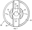
Фиг. 7 - поперечный вид в разрезе сопловой вставки по линии 7-7 на фиг.5 и 6. FIG. 7 is a cross-sectional sectional view of the nozzle insert along line 7-7 of FIGS. 5 and 6.
Фиг.8 - вид спереди сопловой вставки, показанной на фиг.5. Fig. 8 is a front view of the nozzle insert shown in Fig. 5.
Фиг. 9 - вид спереди жидкостного распылителя в соответствии с альтернативным вариантом осуществления, содержащего два отдельных контейнера, установленных один на другом, в котором может быть использована сопловая вставка в соответствии с настоящим изобретением. FIG. 9 is a front view of a liquid atomizer in accordance with an alternative embodiment, comprising two separate containers mounted on top of one another, in which a nozzle insert in accordance with the present invention can be used.
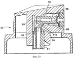
Фиг. 10 - частичный вид в разрезе в увеличенном масштабе верхней части распылителя на фиг. 9, взятый по вертикальной диаметральной плоскости, с сопловой вставкой, в соответствии с настоящим изобретением установленной в приводной кнопке. FIG. 10 is a partial cross-sectional view on an enlarged scale of the upper part of the atomizer of FIG. 9, taken along a vertical diametrical plane, with a nozzle insert, in accordance with the present invention installed in the drive button.
Описание вариантов осуществления изобретения
На фиг. 1-3 показан жидкостной распылитель 10, содержащий контейнер 11 для распыляемого продукта, такого как краска, контейнер 12 с аэрозольным пропеллентом и связывающую соединяющую контейнеры перемычку 13. Аэрозольный пропеллент может быть в форме частично сжиженного пропеллентного газа, находящегося в контейнере под существенным давлением. Отформованная из пластика перемычка 13 может быть закреплена на контейнере 12 защелкиванием. Контейнер 12 имеет стандартный аэрозольный клапан, установленный наверху контейнера в стандартной установочной чашке. Перемычка 13 удерживается непосредственно над контейнером 12 с помощью имеющихся на ней эластичных лапок, входящих в установочную чашку контейнера. С другой стороны, перемычка может удерживаться на контейнере 12 с помощью ее круглого фланца, защелкиваемого снаружи установочной чашки. Перемычка 13 снабжена также нажимным элементом 14, который при нажатии пальцем пользователя на распылитель приводит в действие аэрозольный клапан, выпускающий пропеллентный газ из контейнера 12 во внутренний канал 15, имеющийся в перемычке 13. В центральном отверстии нижней поверхности нажимного элемента 14 закреплен шток аэрозольного клапана, так что когда элемент 14 отжимается вниз, пропеллентный газ проходит вверх по штоку и далее в канал 15 перемычки, как показано на фиг.3 стрелкой.Description of Embodiments
In FIG. 1-3, a liquid sprayer 10 is shown comprising a container 11 for a sprayable product, such as paint, an aerosol propellant container 12 and a
Выходящий из аэрозольного контейнера 12 пропеллентный газ проходит по каналу 15 к входу сопловой вставки 30, расположенной в перемычке 13. В месте выходного отверстия трубки Вентури внутри вставки 30 продукт будет вытягиваться из продуктового контейнера 11 в перемычку 13 в соответствии с принципом работы трубки Вентури. Для крепления перемычки 13 к верху контейнера 11 ее часть, располагаемая над этим контейнером, снабжена резьбой, которая при установке перемычки взаимодействует с резьбой, имеющейся наверху контейнера 11. В контейнере 11 расположена трубка 17, один конец 17a которой расположен вблизи дна контейнера 11, а другой конец 17b окружает трубчатую часть 18 перемычки 13, по внутреннему каналу которой продукт из контейнера проходит в перемычку и затем в место, смежное с выходом трубки Вентури. На выходе трубки Вентури создается вакуум, благодаря которому продукт под давлением воздуха поднимается из контейнера 11 по трубке 17 в перемычку. Продукт и пропеллентный газ смешиваются и выходят из распылителя 10 в виде аэрозольной струи. The propellant gas exiting the aerosol container 12 passes through the
На фиг.4-8 показана новая отформованная пластиковая сопловая вставка 30, причем на фиг.4 показано ее положение в перемычке 13 и взаимодействие с последней. Вначале будут описаны конструкции сопловой вставки 30 и перемычки 13, а затем наиболее существенные, относящиеся к их работе аспекты. Figure 4-8 shows a new molded plastic nozzle insert 30, and figure 4 shows its position in the
Сопловая вставка 30, проходящая вдоль ее центральной продольной оси, имеет заднюю часть 31 с каналом 32, ведущим к трубке Вентури, и переднюю часть 33 с расширительной камерой 34. Промежуточная часть 35 вставки 30 содержит трубку Вентури и два поперечных продуктовых канала 37. The
На фиг.4 показано положение сопловой вставки 30 в переднем концевом отверстии 38 перемычки 13. Наружные поверхности вставки 30 и внутренние поверхности концевого отверстия 38 перемычки имеют в плоскостях, перпендикулярных центральной продольной оси сопловой вставки 30, круглое сечение, за исключением проиллюстрированных и описанных здесь участков ввода продуктовых каналов 37. Сопловая вставка 30 может быть вставлена в перемычку через передний конец распылителя 10 и зафиксирована кольцевым буртиком, имеющимся на боковой стенке отверстия 38 перемычки 13. Как показано на фиг.4, на трубчатую часть 18 перемычки 13 надет конец 17b продуктовой трубки 17, расположенной в контейнере 11. Продукт поднимается по трубке 17 и попадает в цилиндрическое пространство 39 внутри перемычки, окружающее сопловую вставку 30. Из цилиндрического пространства 39 продукт проходит в два диаметрально противоположных канала 37, описываемых ниже, проходящих внутрь вставки 30. Направление потока продукта показано на фиг.4 стрелками. Усеченно-коническая поверхность 40 перемычки 13 обеспечивает направление потока продукта в каналы 37. Цилиндрический канал 32 вставки 30 сообщается вдоль оси с внутренним каналом 15 для пропеллента, расположенным в перемычке 13. Figure 4 shows the position of the nozzle insert 30 in the
На фиг.5-8, где отдельно показана сопловая вставка 30, показано, что цилиндрический канал 32 переходит спереди в постепенно сужающийся канал 50, который, в свою очередь, переходит в узкий концевой цилиндрический канал 51, образующий трубку Вентури, и имеющий круглое выходное отверстие 52. Диаметр отверстия 52, через которое выходит пропеллент из контейнера 12, значительно меньше диаметра расширительной камеры 34, о чем подробнее будет сказано ниже. Передний конец канала 51 расположен в продольном направлении на некотором расстоянии от круглой кромки 53 передней части 33 вставки, окружающей расширительную камеру 34, о чем также речь пойдет ниже. 5-8, where the
Два продуктовых канала 37 проходят сбоку в направлении внутрь к продольной оси сопловой вставки 30. Каналы 37 проходят в продольном направлении вперед от выходного отверстия 52 к передней части 33 вставки 30, и продольно назад от отверстия 52, значительно перекрывая снаружи трубку Вентури и его выходное отверстие 52. Степень перекрытия составляет почти половину продольного просвета каналов 37 в иллюстрируемом примере осуществления изобретения. Как показано на фиг.5 и 6, передние поверхности 54 каналов 37 проходят внутрь и назад. Как показано здесь же, задние поверхности 55 отверстий каналов 37 проходят вперед и внутрь. Усеченно-коническая или, иначе говоря, плавно переходящая на конус поверхность 56, которая окружает канал 51, также служит в качестве направленного внутрь и вперед продолжения задних поверхностей 55 отверстий продуктовых каналов 37, служащих для ровного направления потока продукта внутрь и вперед для его смешивания с пропеллентом в расширительной камере 34. Two
Далее, при описании продуктовых каналов 37 ссылка будет делаться на фиг. 6. Наружное отверстие каждого канала 37 выполнено частично круглым (в продольном направлении) и частично прямоугольным (в поперечном направлении), при этом последняя форма отверстия служит для обеспечения большего потока продукта, чем это могло бы быть в случае полностью круглого отверстия канала для того же продольного направления. На фиг.7 показана другая проекция продуктовых каналов 37, проходящих в сопловую вставку 30, а на фиг.8 показан передний конец выхода вставки 30. Further, when describing the
На фиг.9 показана другая форма жидкостного распылителя, содержащего аэрозольный контейнер 60 с пропеллентом, который навинчен на жидкостной контейнер 61 с подлежащим распылению продуктом. Приводная кнопка 62, при нажатии на которую приводится в действие распылитель, показана в увеличенном масштабе на фиг.10. Жидкий продукт по трубке 63, проходящей через контейнер 60, поднимается вверх, причем верхний конец трубки 63 проходит в центральную часть 64а штока 64 аэрозольного клапана, расположенную в кнопке, причем кнопка имеет центральное отверстие 65, в котором установлена центральная часть 64а штока. Шток 64 клапана имеет также три периферийных отверстия 66, расположенных по периферии штока 64 через 120o и находящихся ниже части 64а штока, причем одно такое отверстие показано в разрезе на фиг.10. При нажатии на кнопку 62 срабатывает через шток стандартный аэрозольный клапан, и отверстия 66 пропускают пропеллент, находящийся в контейнере 60.Figure 9 shows another form of a liquid atomizer comprising an
В кнопке 62, в ее концевом отверстии 67 установлена сопловая вставка 30, подобная описанной со ссылкой на фиг.5-8. При нажатии на кнопку 62 продукт поступает в цилиндрическое пространство 68, окружающее сопловую вставку 30, а пропеллент проходит в периферийный канал 69 в кнопке 62, сообщающийся с отверстиями 66, и в задний конец вставки 30. Сопловая вставка 30 функционирует здесь точно также, как было описано выше с ссылкой на фиг.4-8. Системы, подобные показанной на фиг.9, ранее использовались, при этом в них достигалось соотношение содержания продукта в пропелленте, порядка, пять или шесть к одному для продукта с вязкостью воды. Однако распылитель фиг.9-10, содержащий сопловую вставку 30, описанную ссылкой на фиг.4-8, и кнопку с внутренней конструкцией, описанную с ссылкой на фиг.10, обеспечивает соотношение содержания продукта в пропелленте, порядка, девять к одному для продукта с вязкостью воды. In the
Ряд элементов, описанных здесь и проиллюстрированных на чертежах, является существенным для получения значительного соотношения содержания продукта в пропелленте при осуществлении настоящего изобретения. Принимая во внимание сопловую вставку, описанную с ссылкой на фиг.4-8, необходимо чтобы:
а) Продольное пространство от выходного отверстия 52, из которого выходит газ, простирающееся вперед до входа в расширительную камеру 34, начинающуюся у круговой кромки 53, должно быть таких размеров, чтобы наружная периферия конуса потока пропеллентного газа, выходящего из отверстия 52, оставалась меньшей или равной диаметру периферии круговой кромки 53 до попадания газа в расширительную камеру 34. Конус потока газа схематично показан на фиг. 5 пунктирными линиями. Если периферия этого конуса станет больше до достижения потоком газа круговой кромки 53, выходящий с высокой скоростью из отверстия 52 газ частично пойдет вверх, проходя в поперечные продуктовые каналы 37, создавая вихревые потоки и снижая вакуум, создаваемый трубкой Вентури. Это, несомненно, снизит соотношение содержания продукта в пропелленте.A number of elements described here and illustrated in the drawings are essential to obtain a significant ratio of the product content in the propellant in the implementation of the present invention. Considering the nozzle insert described with reference to FIGS. 4-8, it is necessary that:
a) The longitudinal space from the
б) Диаметр выходного отверстия 52 должен быть значительно меньше диаметра расширительной камеры 34, чтобы с учетом параметров продольного пространства, описанного в п. а), периферия конуса потока газа незначительно превышала диаметр круговой кромки 53 для гарантирования требуемых расширения газа и его смешивания с продуктом. Кроме того, размер выходного отверстия 52 по отношению к диаметру расширительной камеры 34 и продуктовых каналов 37 должен быть таким, чтобы обеспечить требуемое соотношение содержания продукта в пропелленте. b) The diameter of the
с) Необходимо обеспечить существенную степень продольного перекрытия поперечных продуктовых каналов 37 в направлении назад от его выходного отверстия 52. Как указывалось выше, такое перекрытие составляет почти половину размера продольного просвета отверстий продуктовых каналов 37 в описываемом примере осуществления настоящего изобретения. c) It is necessary to provide a substantial degree of longitudinal overlap of the
д) Задние поверхности 55 отверстий продуктовых каналов и усеченно-коническая поверхность 56, окружающая канал 51, должны обеспечивать равномерный поток продукта через отверстия каналов 37 и в поток газа, выходящего из отверстия 52. Острые, выступающие кромки вдоль поверхностей 55 и 56 могут привести к завихрениям в потоке продукта и к снижению в результате соотношения необходимого содержания продукта в пропелленте. Усеченно-коническая поверхность 56 должна заканчиваться спереди по кромке 57, диаметр которой должен быть меньше диаметра круговой кромки 53 расширительной камеры 34, чтобы продукт, выходящий из каналов 37, проходил в поток пропеллентного газа, выходящего из отверстия 52 сужения. e) The rear surfaces 55 of the openings of the product channels and the truncated-
е) Размеры продуктовых каналов 37 должны быть достаточными, чтобы обеспечить необходимое соотношение содержания продукта в пропелленте. Отверстия каналов 37 могут быть увеличены, как показано на фиг.6, за счет придания им частично круглой и частично прямоугольной формы, как указывалось выше. В этом случае, для данного продольного размера продуктовых каналов 37 может быть получен больший поток продукта и может использоваться больший диаметр продуктовой трубки 17. В описываемом примере осуществления изобретения наружный диаметр трубки 17 составляет 0,158 дюйма(4 мм). f) The dimensions of the
ф) Продольная длина расширительной камеры 34 должна быть достаточной для необходимых расширения и смешивания продукта газа, а также для исключения негативного влияния на величину вакуума у продуктовых каналов 37. Однако расширительная камера 34 не должна быть настолько удлиненной, чтобы создавать сопротивление смеси вследствие трения, ухудшающего необходимые характеристики распыления. f) The longitudinal length of the
ж) Для получения необходимого соотношения содержания продукта в пропелленте диаметр входного канала 32 сопловой вставки 30 должен согласовываться с диаметрами других элементов вставки. g) In order to obtain the necessary ratio of the product content in the propellant, the diameter of the
Размеры сопловой вставки для частного примера осуществления настоящего изобретения приведены ниже. Однако для конструкций распылителей, предназначенных для распыления продуктов различных вязкостей и других характеристик, эти размеры могут быть другими. Но эти размеры взаимосвязаны. Считается, что различные размеры отверстий сопловой вставки 30, описанной выше, будут постоянно оставаться пропорциональными друг к другу в соответствии с их площадями. Подобным образом, длина расширительной камеры 34 будет вероятно изменяться пропорционально площадям отверстий вставки. The dimensions of the nozzle insert for a particular embodiment of the present invention are given below. However, for sprayer designs designed to spray products of various viscosities and other characteristics, these sizes may be different. But these sizes are interconnected. It is believed that the various hole sizes of the
Размеры сопловой вставки 30 для частного примера осуществления настоящего изобретения:
Диаметр канала 32 - 0,030 дюйма (0,762 мм)
Диаметр отверстия 52 - 0,012 дюйма (0,305 мм)
Диаметр расширительной камеры 34 - 0,032 дюйма (0,813 мм)
Продольный размер каждого канала 37 - 0,040 дюйма (1,016 мм)
Поперечный размер каждого канала 37 (по диаметру) - 0,050 дюйма (1,27 мм)
Длина сопловой вставки 30 - 0,369 дюйма (9,373 мм)
Длина канала 32 - 0,212 дюйма (5,385 мм)
Длина канала 50 - 0,066 дюйма (1,677 мм)
Длина канала 51 - 0,018 дюйма (0,457 мм)
Длина расширительной камеры 34 - 0,049 дюйма (1,245 мм)
Максимальный наружный диаметр передней части 33 - 0,185 дюйма (4,699 мм)
Наружный диаметр задней части 31 - 0,095 дюйма (2,413 мм)
Угол поверхности 56 к продольной оси - 17o
Угол поверхности 55 к поперечной оси - 11o
Продольное расстояние от кромки 57 до кромки 53 - 0,016 дюйма (0,407 мм)
В описанном и проиллюстрированном примере осуществления настоящего изобретения благодаря сочетанию конструкции сопловой вставки 30 с ее плотной посадкой внутри перемычки 13 или кнопки 62, в месте у поперечных продуктовых каналов 37 достигается высокий вакуум, например, порядка 40-50 см ртутного столба. Вакуум в сочетании с другими существенными конструктивными признаками обеспечивает достижение значительного соотношения содержания продукта в пропелленте, порядка, почти тринадцать к одному для продуктов с вязкостью воды. Это соотношение заметно выше, чем у современных распылителей красок и подобных продуктов. Кроме того, распылители в соответствии с настоящим изобретением могут с успехом распылять виниловые и эмалевые краски.The dimensions of the
Hole Diameter 52 - 0.012 in. (0.305 mm)
Diameter of expansion chamber 34 - 0.032 in. (0.813 mm)
The longitudinal size of each channel is 37 - 0.040 inches (1.016 mm)
The transverse dimension of each channel 37 (in diameter) is 0.050 inches (1.27 mm)
Nozzle Insert Length 30 - 0.369 in. (9.373 mm)
Channel 32 - 0.212 inches (5.385 mm)
Channel length 50 - 0.066 in. (1.677 mm)
Channel 51 - 0.018 in. (0.457 mm)
Expansion Chamber Length 34 - 0.049 in. (1.245 mm)
Maximum Outside Diameter 33 - 0.185 in. (4.699 mm)
Rear Outer Diameter 31 - 0.095 Inches (2.413 mm)
The angle of the
The angle of the
The longitudinal distance from
In the described and illustrated embodiment of the present invention, due to the combination of the design of the
Специалистам понятно, что в настоящее изобретение могут быть, без отклонения от его существа и объема, внесены изменения и/или выполнены его модификации. Поэтому пример осуществления изобретения следует рассматривать как чисто иллюстративный и не ограничивающий изобретение. Professionals it is clear that in the present invention can be, without deviating from its essence and scope, changes are made and / or modifications are made. Therefore, an example embodiment of the invention should be considered as purely illustrative and not limiting of the invention.
Claims (16)
Applications Claiming Priority (2)
| Application Number | Priority Date | Filing Date | Title |
|---|---|---|---|
| US09/030,712 US6062493A (en) | 1998-02-26 | 1998-02-26 | Sprayer for liquids and nozzle insert |
| US09/030,712 | 1998-02-26 |
Related Child Applications (1)
| Application Number | Title | Priority Date | Filing Date |
|---|---|---|---|
| RU2001103928/12A Division RU2245196C2 (en) | 1998-02-26 | 1999-02-12 | Connection partition used with liquid sprayer |
Publications (2)
| Publication Number | Publication Date |
|---|---|
| RU2000124400A RU2000124400A (en) | 2002-08-20 |
| RU2205705C2 true RU2205705C2 (en) | 2003-06-10 |
Family
ID=21855617
Family Applications (2)
| Application Number | Title | Priority Date | Filing Date |
|---|---|---|---|
| RU2000124400/12A RU2205705C2 (en) | 1998-02-26 | 1999-02-12 | Liquid sprayer and nozzle insert |
| RU2001103928/12A RU2245196C2 (en) | 1998-02-26 | 1999-02-12 | Connection partition used with liquid sprayer |
Family Applications After (1)
| Application Number | Title | Priority Date | Filing Date |
|---|---|---|---|
| RU2001103928/12A RU2245196C2 (en) | 1998-02-26 | 1999-02-12 | Connection partition used with liquid sprayer |
Country Status (18)
| Country | Link |
|---|---|
| US (3) | US6062493A (en) |
| EP (1) | EP1056547B1 (en) |
| JP (1) | JP4237403B2 (en) |
| KR (1) | KR100507821B1 (en) |
| CN (1) | CN1115204C (en) |
| AU (1) | AU742559B2 (en) |
| BR (1) | BR9908247A (en) |
| CA (1) | CA2321566A1 (en) |
| CZ (1) | CZ20003053A3 (en) |
| DE (1) | DE69909056T2 (en) |
| ES (1) | ES2201746T3 (en) |
| HU (1) | HUP0100894A3 (en) |
| ID (1) | ID26935A (en) |
| NO (1) | NO20004214L (en) |
| PL (1) | PL342489A1 (en) |
| RU (2) | RU2205705C2 (en) |
| UA (1) | UA62997C2 (en) |
| WO (1) | WO1999043441A1 (en) |
Cited By (1)
| Publication number | Priority date | Publication date | Assignee | Title |
|---|---|---|---|---|
| RU2571133C2 (en) * | 2011-02-09 | 2015-12-20 | Зм Инновейтив Пропертиз Компани | Nozzle adapters and paint blower spraying head components |
Families Citing this family (59)
| Publication number | Priority date | Publication date | Assignee | Title |
|---|---|---|---|---|
| US6000583A (en) * | 1992-02-24 | 1999-12-14 | Homax Products, Inc. | Aerosol spray texturing devices |
| US7278590B1 (en) | 1992-02-24 | 2007-10-09 | Homax Products, Inc. | Systems and methods for applying texture material to ceiling surfaces |
| US5310095A (en) * | 1992-02-24 | 1994-05-10 | Djs&T Limited Partnership | Spray texturing apparatus and method having a plurality of dispersing tubes |
| US6062493A (en) * | 1998-02-26 | 2000-05-16 | Abplanalp; Robert Henry | Sprayer for liquids and nozzle insert |
| WO2001039892A1 (en) * | 1999-12-06 | 2001-06-07 | Laibovitz Robert A | Apparatus and method for delivery of small volumes of liquid |
| WO2001092131A1 (en) * | 2000-05-30 | 2001-12-06 | Taisho Pharmaceutical Co., Ltd. | Aerosol container |
| US6394364B1 (en) | 2000-09-29 | 2002-05-28 | Robert Henry Abplanalp | Aerosol spray dispenser |
| EP1461125A4 (en) | 2001-12-13 | 2007-03-28 | Advanced Specialized Technolog | Spraying system for dispersing and disseminating fluids |
| US7906473B2 (en) * | 2002-09-13 | 2011-03-15 | Bissell Homecare, Inc. | Manual spray cleaner |
| FR2844728A1 (en) * | 2002-09-25 | 2004-03-26 | Patrick Marc Loubeyre | Liquid product projection device comprises compressed air tank, product tan and projection hose connected to tanks by flexible hose |
| JP4339610B2 (en) * | 2003-02-25 | 2009-10-07 | 株式会社ダイゾー | Liquid injection adapter |
| US7500621B2 (en) | 2003-04-10 | 2009-03-10 | Homax Products, Inc. | Systems and methods for securing aerosol systems |
| KR100500164B1 (en) * | 2003-05-31 | 2005-07-11 | 이용해 | a suction apparatus of leak oil in soil |
| FR2859650B1 (en) * | 2003-09-12 | 2006-02-24 | Gloster Sante Europ | APPARATUS FOR BRUSTING A LIQUID COMPOSITION |
| US7118049B2 (en) * | 2003-10-30 | 2006-10-10 | Meadwestvaco Corporation | Hose-end sprayer assembly |
| US20050145270A1 (en) * | 2003-12-31 | 2005-07-07 | Ray R. K. | Pressure washer with injector |
| US20050161531A1 (en) | 2004-01-28 | 2005-07-28 | Greer Lester R.Jr. | Texture material for covering a repaired portion of a textured surface |
| KR100622987B1 (en) | 2004-06-10 | 2006-09-19 | 한국에너지기술연구원 | Twin Fluid Atomizing Nozzle |
| US7677420B1 (en) | 2004-07-02 | 2010-03-16 | Homax Products, Inc. | Aerosol spray texture apparatus for a particulate containing material |
| JP4838988B2 (en) * | 2004-07-13 | 2011-12-14 | 黒田精工株式会社 | Mist supply nozzle |
| US7487893B1 (en) | 2004-10-08 | 2009-02-10 | Homax Products, Inc. | Aerosol systems and methods for dispensing texture material |
| US7407117B2 (en) * | 2004-10-28 | 2008-08-05 | Meadwestvaco Calmar, Inc. | Liquid sprayer assembly |
| US7188786B2 (en) * | 2004-10-28 | 2007-03-13 | Meadwestvaco Corporation | Hose-end sprayer assembly |
| WO2006058433A1 (en) * | 2004-12-03 | 2006-06-08 | Multi-Vet Ltd. | Fluid delivery system for dispensing an active substance in spray form |
| WO2006119923A1 (en) | 2005-05-06 | 2006-11-16 | Dieter Wurz | Spray nozzle, spray device and the operation method thereof |
| US7237728B1 (en) * | 2005-05-19 | 2007-07-03 | Rodney Laible | Hand-held dispenser |
| JP5240886B2 (en) * | 2005-06-27 | 2013-07-17 | 国立大学法人 熊本大学 | Fine droplet generator, fine droplet generator, and fine droplet generation method |
| US7607591B2 (en) * | 2005-10-26 | 2009-10-27 | Hallmark Cards, Incorporated | Airbrush |
| WO2007065197A1 (en) * | 2005-12-06 | 2007-06-14 | Datadot Technology Ltd | The application of microdots and other identifiers to an article |
| US8344056B1 (en) | 2007-04-04 | 2013-01-01 | Homax Products, Inc. | Aerosol dispensing systems, methods, and compositions for repairing interior structure surfaces |
| US8580349B1 (en) | 2007-04-05 | 2013-11-12 | Homax Products, Inc. | Pigmented spray texture material compositions, systems, and methods |
| US9382060B1 (en) | 2007-04-05 | 2016-07-05 | Homax Products, Inc. | Spray texture material compositions, systems, and methods with accelerated dry times |
| US7572107B2 (en) | 2007-04-20 | 2009-08-11 | Adapco, Inc. | Ultra low volume chemical delivery system and method |
| FR2935362B1 (en) * | 2008-09-04 | 2010-09-10 | Valois Sa | DEVICE FOR DISPENSING FLUID PRODUCT. |
| FR2940923B1 (en) * | 2009-01-13 | 2012-02-24 | Gloster Europe | MIXING APPARATUS WITH A FRACTIONING INJECTOR |
| CN102355956A (en) | 2009-01-26 | 2012-02-15 | 3M创新有限公司 | Liquid spray gun, spray gun platform, and spray head assembly |
| CN101607238B (en) * | 2009-07-17 | 2012-08-29 | 何启烽 | Device for jetting liquid and usage thereof |
| KR101222370B1 (en) | 2011-03-04 | 2013-01-16 | 정영주 | Apparatus for discharging fluid |
| ES2845618T3 (en) | 2011-07-28 | 2021-07-27 | 3M Innovative Properties Co | Spray head unit with integrated air cap / nozzle for a liquid spray gun |
| US9248457B2 (en) | 2011-07-29 | 2016-02-02 | Homax Products, Inc. | Systems and methods for dispensing texture material using dual flow adjustment |
| US9156042B2 (en) | 2011-07-29 | 2015-10-13 | Homax Products, Inc. | Systems and methods for dispensing texture material using dual flow adjustment |
| BR112014008900A2 (en) | 2011-10-12 | 2017-04-25 | 3M Innovative Properties Co | spray head assemblies for liquid spray guns, spray gun, and method of changing a liquid handling core from a spray head assembly |
| EP2766095B1 (en) * | 2011-10-12 | 2017-03-15 | Aptargroup, Inc. | Fan spray structure for use in dispensing actuator |
| EP2822699B1 (en) | 2012-03-06 | 2021-12-22 | 3M Innovative Properties Company | Spray gun having internal boost passageway |
| US11167298B2 (en) | 2012-03-23 | 2021-11-09 | 3M Innovative Properties Company | Spray gun barrel with inseparable nozzle |
| US9156602B1 (en) | 2012-05-17 | 2015-10-13 | Homax Products, Inc. | Actuators for dispensers for texture material |
| US9435120B2 (en) | 2013-03-13 | 2016-09-06 | Homax Products, Inc. | Acoustic ceiling popcorn texture materials, systems, and methods |
| JP6449874B2 (en) | 2013-07-15 | 2019-01-09 | スリーエム イノベイティブ プロパティズ カンパニー | Air cap with surface insert for liquid spray gun |
| US9776785B2 (en) | 2013-08-19 | 2017-10-03 | Ppg Architectural Finishes, Inc. | Ceiling texture materials, systems, and methods |
| KR101501746B1 (en) * | 2013-09-27 | 2015-03-11 | (주)레이원 | Spray apparatus of liquid substance |
| MD843Z (en) * | 2014-04-17 | 2015-07-31 | Институт Почвоведения, Агрохимии И Охраны Почв "Nicolae Dimo" | Process for soil fertilization |
| CN104016011B (en) * | 2014-06-23 | 2017-01-18 | 惠州市德莱仕科技有限公司 | Gas-liquid separation type spray tank |
| USD787326S1 (en) | 2014-12-09 | 2017-05-23 | Ppg Architectural Finishes, Inc. | Cap with actuator |
| US10518962B2 (en) | 2016-05-26 | 2019-12-31 | Pro Form Products Ltd. | Two aerosol can injection system |
| US10556738B2 (en) | 2016-05-26 | 2020-02-11 | Pro Form Products Ltd. | Two aerosol can injection system |
| TWI688529B (en) * | 2017-10-06 | 2020-03-21 | 日商大日本除蟲菊股份有限公司 | Spray member for trigger-type aerosol, and aerosol product |
| CN109692764A (en) * | 2017-10-20 | 2019-04-30 | 美的集团股份有限公司 | Atomizer and cooling device with it |
| CN108580084A (en) * | 2018-07-26 | 2018-09-28 | 太原市华豹装饰工程有限公司 | A kind of aqueous self-spraying paint device of external hanging type and its application method |
| US10940493B2 (en) * | 2018-07-26 | 2021-03-09 | S. C. Johnson & Son, Inc. | Actuator and nozzle insert for dispensing systems |
Family Cites Families (13)
| Publication number | Priority date | Publication date | Assignee | Title |
|---|---|---|---|---|
| US912106A (en) * | 1908-03-28 | 1909-02-09 | Edwin J Frazier | Multiple-fluid sprayer. |
| US1989912A (en) * | 1933-02-27 | 1935-02-05 | Adam A Breuer | Steam sprayer |
| FR1150416A (en) * | 1956-05-02 | 1958-01-13 | Vaporisateurs Marcel Franck | Improvements to sprayers, in particular to perfume sprayers |
| US2954678A (en) * | 1957-07-18 | 1960-10-04 | Ass For Physiologic Res Inc | Method of dispersing materials |
| FR1243445A (en) * | 1959-08-29 | 1960-10-14 | Improvements to automatic sprayers for liquids | |
| US3289949A (en) * | 1964-07-09 | 1966-12-06 | Geigy Chem Corp | Pushbutton dispenser for products in the fluid state |
| US3305134A (en) * | 1965-10-21 | 1967-02-21 | Union Carbide Corp | Automatic spray device |
| US3437272A (en) * | 1966-02-02 | 1969-04-08 | Abplanalp Robert H | Valve actuator for pressurized dispensers |
| US3442425A (en) * | 1967-12-28 | 1969-05-06 | Geigy Chem Corp | Plug valve assembly for aerosol bomb type dispensers of fluid products |
| US3575319A (en) * | 1968-07-11 | 1971-04-20 | Upjohn Co | Portable dispenser for polymer foams |
| DE2127651C3 (en) * | 1970-06-04 | 1975-09-25 | Ciba-Geigy Ag, Basel (Schweiz) | Atomizing device |
| US4382552A (en) * | 1981-09-08 | 1983-05-10 | The O. M. Scott & Sons Company | Liquid applicator |
| US6062493A (en) * | 1998-02-26 | 2000-05-16 | Abplanalp; Robert Henry | Sprayer for liquids and nozzle insert |
-
1998
- 1998-02-26 US US09/030,712 patent/US6062493A/en not_active Expired - Lifetime
-
1999
- 1999-02-12 KR KR10-2000-7009420A patent/KR100507821B1/en not_active IP Right Cessation
- 1999-02-12 CA CA002321566A patent/CA2321566A1/en not_active Abandoned
- 1999-02-12 JP JP2000533229A patent/JP4237403B2/en not_active Expired - Lifetime
- 1999-02-12 ID IDW20001855A patent/ID26935A/en unknown
- 1999-02-12 EP EP99936042A patent/EP1056547B1/en not_active Expired - Lifetime
- 1999-02-12 DE DE69909056T patent/DE69909056T2/en not_active Expired - Lifetime
- 1999-02-12 AU AU32904/99A patent/AU742559B2/en not_active Ceased
- 1999-02-12 HU HU0100894A patent/HUP0100894A3/en unknown
- 1999-02-12 ES ES99936042T patent/ES2201746T3/en not_active Expired - Lifetime
- 1999-02-12 CN CN99804306A patent/CN1115204C/en not_active Expired - Fee Related
- 1999-02-12 BR BR9908247-0A patent/BR9908247A/en not_active IP Right Cessation
- 1999-02-12 WO PCT/US1999/003005 patent/WO1999043441A1/en active IP Right Grant
- 1999-02-12 CZ CZ20003053A patent/CZ20003053A3/en unknown
- 1999-02-12 RU RU2000124400/12A patent/RU2205705C2/en not_active IP Right Cessation
- 1999-02-12 RU RU2001103928/12A patent/RU2245196C2/en not_active IP Right Cessation
- 1999-02-12 PL PL99342489A patent/PL342489A1/en unknown
- 1999-04-14 US US09/291,317 patent/US6036111A/en not_active Expired - Lifetime
- 1999-12-02 UA UA2000095502A patent/UA62997C2/en unknown
-
2000
- 2000-03-13 US US09/524,035 patent/US6254015B1/en not_active Expired - Lifetime
- 2000-08-23 NO NO20004214A patent/NO20004214L/en not_active Application Discontinuation
Cited By (1)
| Publication number | Priority date | Publication date | Assignee | Title |
|---|---|---|---|---|
| RU2571133C2 (en) * | 2011-02-09 | 2015-12-20 | Зм Инновейтив Пропертиз Компани | Nozzle adapters and paint blower spraying head components |
Also Published As
| Publication number | Publication date |
|---|---|
| JP2002504431A (en) | 2002-02-12 |
| CA2321566A1 (en) | 1999-09-02 |
| NO20004214D0 (en) | 2000-08-23 |
| EP1056547B1 (en) | 2003-06-25 |
| EP1056547A4 (en) | 2002-08-28 |
| NO20004214L (en) | 2000-10-23 |
| DE69909056D1 (en) | 2003-07-31 |
| ES2201746T3 (en) | 2004-03-16 |
| CZ20003053A3 (en) | 2001-12-12 |
| ID26935A (en) | 2001-02-22 |
| KR20010041314A (en) | 2001-05-15 |
| US6062493A (en) | 2000-05-16 |
| WO1999043441A1 (en) | 1999-09-02 |
| CN1294534A (en) | 2001-05-09 |
| HUP0100894A2 (en) | 2001-06-28 |
| CN1115204C (en) | 2003-07-23 |
| RU2245196C2 (en) | 2005-01-27 |
| KR100507821B1 (en) | 2005-08-10 |
| EP1056547A1 (en) | 2000-12-06 |
| US6036111A (en) | 2000-03-14 |
| US6254015B1 (en) | 2001-07-03 |
| DE69909056T2 (en) | 2004-05-19 |
| UA62997C2 (en) | 2004-01-15 |
| JP4237403B2 (en) | 2009-03-11 |
| AU742559B2 (en) | 2002-01-03 |
| PL342489A1 (en) | 2001-06-04 |
| HUP0100894A3 (en) | 2001-07-30 |
| BR9908247A (en) | 2000-10-31 |
| AU3290499A (en) | 1999-09-15 |
Similar Documents
| Publication | Publication Date | Title |
|---|---|---|
| RU2205705C2 (en) | Liquid sprayer and nozzle insert | |
| US3913842A (en) | Spray head for aerosol can | |
| EP1320416B1 (en) | Aerosol spray dispenser | |
| US4286735A (en) | Squeeze dispenser with flexible conduit with attached, weighted and grooved end | |
| CA1267666A (en) | Two piece foamer nozzle assembly | |
| AU2009230810B2 (en) | Dome pump spray assembly | |
| RU2000124400A (en) | SPRAY FOR LIQUIDS AND NOZZLE INSERT | |
| ES2851723T3 (en) | Application device | |
| WO1990003227A1 (en) | Foam-off nozzle assembly with barrel screen insert for use in a trigger sprayer | |
| EP3442715B1 (en) | Squeeze sprayer closure | |
| NO329202B1 (en) | Improvements in and related to liquid dispensing apparatus | |
| EP1230984B1 (en) | Airless sprayer for a squeeze bottle | |
| JPH07256162A (en) | Foaming nozzle | |
| US6250568B1 (en) | Squeeze bottle aspirator | |
| AU2001245655A1 (en) | Method of using a dispensing head for a squeeze dispenser | |
| JPH0646865Y2 (en) | Spraying device | |
| US20170173599A1 (en) | Modular Nozzle Assembly and Fluidic Plate Apparatus and Method for Selectively Creating 2-D or 3-D Spray Patterns | |
| EP3508278B1 (en) | Cosmetic air brush | |
| JPH0335385Y2 (en) | ||
| AU625077C (en) | Foam-off nozzle assembly with barrel screen insert for use in a trigger sprayer | |
| MXPA00009390A (en) | Squeeze bottle aspirator | |
| MXPA00008279A (en) | Sprayer for liquids and nozzle insert | |
| JP2003024843A (en) | Spray |
Legal Events
| Date | Code | Title | Description |
|---|---|---|---|
| MM4A | The patent is invalid due to non-payment of fees |
Effective date: 20090213 |