US3442425A - Plug valve assembly for aerosol bomb type dispensers of fluid products - Google Patents
Plug valve assembly for aerosol bomb type dispensers of fluid products Download PDFInfo
- Publication number
- US3442425A US3442425A US694309A US3442425DA US3442425A US 3442425 A US3442425 A US 3442425A US 694309 A US694309 A US 694309A US 3442425D A US3442425D A US 3442425DA US 3442425 A US3442425 A US 3442425A
- Authority
- US
- United States
- Prior art keywords
- valve
- gasket
- propellant
- rod
- plug valve
- Prior art date
- Legal status (The legal status is an assumption and is not a legal conclusion. Google has not performed a legal analysis and makes no representation as to the accuracy of the status listed.)
- Expired - Lifetime
Links
- 239000012530 fluid Substances 0.000 title description 19
- 239000000443 aerosol Substances 0.000 title description 6
- 239000003380 propellant Substances 0.000 description 45
- 238000007789 sealing Methods 0.000 description 12
- 239000013543 active substance Substances 0.000 description 11
- 239000007788 liquid Substances 0.000 description 9
- 239000007921 spray Substances 0.000 description 6
- 239000000463 material Substances 0.000 description 3
- 239000000843 powder Substances 0.000 description 3
- 239000004215 Carbon black (E152) Substances 0.000 description 2
- 238000010276 construction Methods 0.000 description 2
- 239000007789 gas Substances 0.000 description 2
- 229930195733 hydrocarbon Natural products 0.000 description 2
- 150000002430 hydrocarbons Chemical class 0.000 description 2
- 239000002184 metal Substances 0.000 description 2
- 239000003795 chemical substances by application Substances 0.000 description 1
- 238000002788 crimping Methods 0.000 description 1
- 238000011031 large-scale manufacturing process Methods 0.000 description 1
- 238000004519 manufacturing process Methods 0.000 description 1
- 230000002093 peripheral effect Effects 0.000 description 1
- 230000002035 prolonged effect Effects 0.000 description 1
- 238000005507 spraying Methods 0.000 description 1
- 239000000126 substance Substances 0.000 description 1
Images


Classifications
-
- B—PERFORMING OPERATIONS; TRANSPORTING
- B05—SPRAYING OR ATOMISING IN GENERAL; APPLYING FLUENT MATERIALS TO SURFACES, IN GENERAL
- B05B—SPRAYING APPARATUS; ATOMISING APPARATUS; NOZZLES
- B05B7/00—Spraying apparatus for discharge of liquids or other fluent materials from two or more sources, e.g. of liquid and air, of powder and gas
- B05B7/24—Spraying apparatus for discharge of liquids or other fluent materials from two or more sources, e.g. of liquid and air, of powder and gas with means, e.g. a container, for supplying liquid or other fluent material to a discharge device
- B05B7/2402—Apparatus to be carried on or by a person, e.g. by hand; Apparatus comprising containers fixed to the discharge device
- B05B7/2405—Apparatus to be carried on or by a person, e.g. by hand; Apparatus comprising containers fixed to the discharge device using an atomising fluid as carrying fluid for feeding, e.g. by suction or pressure, a carried liquid from the container to the nozzle
- B05B7/2424—Apparatus to be carried on or by a person, e.g. by hand; Apparatus comprising containers fixed to the discharge device using an atomising fluid as carrying fluid for feeding, e.g. by suction or pressure, a carried liquid from the container to the nozzle the carried liquid and the main stream of atomising fluid being brought together downstream of the container before discharge
-
- B—PERFORMING OPERATIONS; TRANSPORTING
- B65—CONVEYING; PACKING; STORING; HANDLING THIN OR FILAMENTARY MATERIAL
- B65D—CONTAINERS FOR STORAGE OR TRANSPORT OF ARTICLES OR MATERIALS, e.g. BAGS, BARRELS, BOTTLES, BOXES, CANS, CARTONS, CRATES, DRUMS, JARS, TANKS, HOPPERS, FORWARDING CONTAINERS; ACCESSORIES, CLOSURES, OR FITTINGS THEREFOR; PACKAGING ELEMENTS; PACKAGES
- B65D83/00—Containers or packages with special means for dispensing contents
- B65D83/14—Containers for dispensing liquid or semi-liquid contents by internal gaseous pressure, i.e. aerosol containers comprising propellant
- B65D83/60—Containers for dispensing liquid or semi-liquid contents by internal gaseous pressure, i.e. aerosol containers comprising propellant with contents and propellant separated
- B65D83/66—Containers for dispensing liquid or semi-liquid contents by internal gaseous pressure, i.e. aerosol containers comprising propellant with contents and propellant separated initially separated and subsequently mixed, e.g. in a dispensing head
Definitions
- a plug valve assembly for dispensers of fluid products and having a container for containing the fluid product to be dispensed and adapted to accommodate a propellant cartridge within the product container, said plug valve assembly comprising a hollow rod, a valve actuator on the upper end of said rod and having a nozzle therein, a cap member having an aperture therein through which the hollow rod is movable, a valve body on the lower side of said cap member and into which said valve rod is slideable through said aperture, the assembly having the flow path for the fluid product obturated by gasket means, a propellant cartridge secured to said valve body, and a dip tube extending through said propellant cartridge to the bottom of said valve body and being connected to said valve rod and opening into said flow path, said gasket means being a double gasket around said valve rod for sealing the openings therein which connect to the fluid product flow path, said dip tube being in fluid-tight en gagement with said propellant cartridge where it passes therethrough.
- This invention relates to a plug valve with push-button control for dispenser appliances ofproducts in liquid or powder form, and more particularly relates to such valve for dispenser appliances of the aerosol bomb type, especially of the type having triple obturation.
- the valve comprises a mobile member actuated by a valve actuator in the form of a push-button simultaneously controlling a high pressure obturator and two low pressure obturators.
- the dispenser has an outer product container containing an active agent and a propellant cartridge in whch a propellant is accommodated, which propellant generally consists of a liquefied hydrocarbon, the liquid stage being in equilibrium with the vapor stage when the propellant is quiescent.
- propellant generally consists of a liquefied hydrocarbon
- the passage of the gaseous propellant toward a spray nozzle contained in the valve actuator for the plug valve is controlled by the high pressure obturator.
- the dispenser further comprises a dip tube which dips into the active agent and which is in communication with the spray nozzle, the flow of the active agent therethrough being controlled by one of the low pressure obturators.
- the other low pressure obturator controls the admission of atmospheric air into the receptacle as it is emptied for the purpose of equalizing the internal and external pressures, this admission taking place concurrently with the other operations when the push-button valve actuator is operated.
- the dip tube is independent of the propellant cartridge. It is fixed to the body of the plug valve and dips directly into the material in the product container.
- Such dispensers are to some extent easy to produce and assemble, but they only have one obturator, a high pressure obturator, for the propellant.
- the dip tube communicates directly with the spray nozzle. It follows that when the dispenser is at rest, the equalization of the pressure between the interior of the product container and the atmosphere must be effected automatically through the unvalved dip tube.
- there is the serious drawback of possible leakage either when the dispenser is placed head downwards, or when it is heated, for example by being exposed to the sun, because of the expansion of the gases it contains, which causes the active agent to flow up through the dip tube and out the spray nozzle.
- the pressure in the product container will be reduced, which reduces the rate of expulsion of the active agent.
- An object of the invention is to provide a sealing gasket means where the dip tube is attached to the plug valve which obturates the dip tube when the plug valve is in the closed position.
- a further object of the present invention is to overcome these drawbacks and to provide triple obturation of a dispenser having dip tube which passes through a propellant cartridge which is within the product container.
- a still further object of the invention is to provide such triple obturation in a manner in which leakage of the active agent through the dip tube and leakage of the propellant into the diptube is prevented.
- a still further object of the invention is to provide a dispenser which can be produced easily, and in which the parts can be of plastic and need not be made of excessively close manufacturing tolerances, because such close tolerances are not suited to the utilization of plastic components in large scale production.
- the push-button actuated plug valve for dispensers -for products in liquid or powder form which dispenser has a liquefied propellant under pressure containeld in a propellant cartridge accommodated inside a product container containing the active agent, has three separate flow paths, one for the propellant, one for the liquid to be sprayed and one for connecting the interior of the product container with the atmosphere respectively, each of these flow paths being controlled by an obturator.
- the active agent flow path comprises a dip tube which dips into the agent, passes through the propellant reservoir and extends to the base of the plug valve, and the valve comprises a hollow sliding rod which passes through two sealing gasket means, one acting as a double obturator for both the propellant flow path and one of the other flow paths, while the second sealing gasket means is a double gasket which acts as an obturator for the third flow path.
- the sealing gasket means acting as the double obturator is arranged in the propellant flow path and the flow path connecting the product container with the atmosphere, while the second sealing gasket means controls the active agent flow path.
- the arrangement of the obturators and flow paths is such that the active agent flow path is opened before the propellant flow path and the flow path between the pro'duct container and the atmosphere, and the closing of said flow paths is in the reverse order.
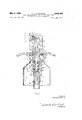
- FIGURE 1 is a sectional view, on a small scale, of a dispenser of the aerosol bomb type with a plug valve in accordance with the invention fitted thereon;
- FIGURE 2 is an axial sectional view, on a larger scale, showing the plug valve in the closed position
- FIGURE 3 is a view similar to FIGURE 2 showing the plug valve in the valve actuated position
- FIGURE 4 is a view similar to FIGURE 1 showing a modified form of dispenser.
- the plug valve of the invention is applied to a push-botton valve actuator type dispenser for spraying a substance 1 in liquid or powder form (FIGURE 1) contained in a product container 2 of plastic or metal.
- the plug valve is mounted on a product container cap 3 for capping the product container 2.
- the periphery of the cap 3 has a depending flange which engages with a reduced diameter collar 4 of the container 2, and the flange can be welded peripherally along the collar or bonded firmly to it.
- the cap 3 has at its center an aperture 5 through which extents a rod 6, the upper end of which is covered by the push-button valve actuator 8 which is secured thereto.
- the actuator 8 continues a spray nozzle insert 9 defining the spray nozzle.
- the cap 3 also has an annular depending projection 11 for engagement around a lateral annular projection 12 on a propellant cartridge 13 of metal or plastic and containing for instance a liquefied gas such as a fluorochlorinated hydrocarbon.
- the propellant cartridge 13 is accommodated inside the contain 2.
- the dispenser has a dip tube 14 for feeding the liquid '1 to be sprayed towards the nozzle insert 9.
- the tube 14 passes through the bottom 15 of the propellant cartridge 3 through a fluid tight joint, and then axially through the cartridge. Fluid tightness is ensured by a crimping element or the like 16.
- the plug valve further comprises a hollow valve body 18, of cast material for example.
- This hollow body is also accommodated inside the reservoir 13 and has at its upper end a peripheral bulge 19 which fits in the annular projections 12 of the cartridge 13, which in turn is gripped by the ldepending projection 11, so that the propellant cartridge 13 and the valve body '18 therein is suspended from the underneath side of the cap 3.
- the first gasket means in the form of a flexible annular sealing gasket 21 through the center of which passes the rod, the sealing gasket 21 engaging in an annular constriction 22 in this rod.
- a shoulder is provided on the lower end of rod 6 and is in turn positioned on the upper end of a plug 23 of greater diameter than the rod 6.
- the central bore in the rod 6 is aligned with the central bore 45a in the plug 23.
- Plug 23 and shoulder 25 are accommodated in valve up 18a inside the valve body 18.
- the cap 3 has an inner annular projection 24 around the aperture 5.
- the surface of the sealing gasket 21 opposite the projection 24 is engaged by the shoulder 25, the dimensions of these components being suflicient to permit the gasket 21 to flex when the plug valve is operated, as will be described later.
- a bleeder duct 41 extends from just behind the projection 24 and opens into the interior of the product container 2.
- the shoulder 25 is urged, when the valve is at rest, against the gasket 21 by a spring 26 which is supported between a second shoulder 27 on the bottom of the plug 23 and a collar 28 in the form of a ring in the bottom of valve cup 18a, Extending axially through the spring 26 from plug 23 is a hollow tubular extension 29 extending to and entering the tube 14 through the second gasket means in the form of a pair of flexible sealing gaskets 31 and 31a.
- Gasket 31 is held between the collar 28 and the bottom 18a of the hollow valve body 18, and the gasket 31a is held between the end of a tubular member 61 and the bottom of a recess 32a, defined by a sleeve 32 projecting from the valve body 18.
- the end of the tube 14 is secured to the lower end of the extension 29.
- the duct is blocked near the lower end by a diaphragm 45b which in the closed position of the valve lies within upper gasket 31, and transverse orifices 46 and 46a are provided above and below the diaphragm.
- the gaskets 31 and 31a are spaced along the length of the tubular extension 29 a distance greater than the distance between orifices 46 and 46a.
- the duct 45 opens into a duct 47 in the push-button valve actuator 8 which communicates with an annular chamber 48 in the actuator 8.
- radial ducts 49 in the nozzle insert 9 which nozzle insert has a nozzle therein having a convergent portion 51 and a divergent portion 52 connected by a choke portion 53, the portions together forming a venturi in a known manner.
- the radial ducts 49 extend from the choke portions 53.
- the axial duct 45 in the rod 6 is surrounded by an annular duct 55 provided in the upper part of the rod, annular duct 45 opening at its lower end into the annular constriction 22 through an orifice 56.
- the orifice 56 is above the inner lip of the annular gasket 21.
- the annular duct 55 communicates with a recess 57 in the actuator 8 into which recess the convergent portion 51 of the nozzle insert opens.
- sealing gasket 21 acts as a double obturator. It is positioned, in fact, both in the propellant flow path and in the flow path for placing the interior of the container when the push-button actuator 7 is pressed down.
- High pressure obturation is ensured by contact between the shoulder 25 and the surface 20 of the gasket 21 facing towards the cartridge 13.
- the pressure of the shoulder 25 on the surface 20 comes both from the spring 26 and the vapor pressure of the propellant contained in the cartridge 13.
- the cartridge communicates with the body 18 through one or more apertures 30 in the valve body.
- the other surface 40 of the gasket 21 is brought into relationship with the gaseous medium above the liquid 1 contained in the receptacle 2 through the radial bleeder duct 41 in the annular projection 11.
- This bleeder duct communicates with an annular chamber 42 provided in the cap 3 and is separated from the bore 5 by the projection 24.
- the assembly of the flexible sealing gaskets 31 and 31a and the hollow-tubular extension 29 constitutes the single obturator of the plug valve, this obturator serving for controlling the passage of the liquid 1 from the tube 14 towards the nozzle insert 9.
- the assembly is capped by the cap 3 and the projection 11 of this latter is hot set onto the annular projection 12 on the cartridge 13 with the dip tube extending through the bottom thereof.
- the head 8 provided with the nozzle insert 9 is force fitted onto the upper end of rod 6.
- the plug valve assembly is then mounted on a product container 2 by securing the depending flange to collar 4.
- the propellant in the gaseous state passes from the cartridge 13 into the cup 18a through the orifice then escapes through the orifice 56, flows along the annular duct 55, through the recess 57 and the nozzle in the nozzle insert 9 which it traverses axially (arrow P).
- FIG. 4 A modified embodiment of the invention is shown in FIG. 4 in which the same parts have been given the same reference numbers.
- the valve assembly is secured to the cap 70 for the cartridge 13, the gasket 21 being held between the cap 70 and the top of the valve body 18, and obturating only the opening 56 into the propellant passage 55.
- the cap 70 is secure to the body 13 of the propellant cartridge in a conventional manner, and the product container 71 is secured to the propellant cartridge in a likewise conventional manner.
- the valve structure and the double gasket construction are the same as the embodiment shown in FIGS. 1-3.
- a plug valve assembly for dispensers of fluid products and having a product container for containing the fluid product to be dispensed and adapted to accommodate a propellant cartridge within the product container, said plug valve assembly comprising a hollow rod, a valve actuator on the upper end of said rod and having a nozzle therein, a cap member having an aperture therein through which the hollow rod is movable, a valve body on the lower side of said cap member and into which said valve rod is slideable through said aperture, the assembly having at least two flow paths therethrough, one for the propellant and one for the fluid product, a first flexible gasket means in said assembly through which said hollow rod passes obturating said propellant flow path and a second flexible gasket means obturating the fluid product flow path, a propellant cartridge secured to said valve body, and a dip tube extending through said propellant cartridge to the bottom of said valve body and being connected to said valve rod and opening into said product flow path, said second gasket means being a double gasket around said valve rod, said valve rod having flow path
- a plug valve assembly as claimed in claim 2 in which said double gasket comprises anupper gasket adjacent which said diaphragm is positioned and which blocks the opening in the valve rod on the upper side of the diaphragm when the rod is in the raised position, said double gasket further including a lower gasket spaced from said upper gasket along the length of the valve rod a distance greater than the distance between the openings on either side of the diaphragm.
- a plug valve assembly for dispensers of fluid products and having a product container for containing the fluid product to be dispensed and adapted to accommodate a propellant cartridge within the product container, said plug valve assembly comprising a hollow rod, a valve actuator on the upper end of said rod and having a nozzle therein, a cap member having an aperture therein through which the hollow rod is movable, a valve body on the lower side of said cap member and into which said valve rod is slideable through said aperture, the assembly having three flow paths therethrough, one for the propellant, one for the fluid product, and one for the atmospheric air to flow into the space within the product container above the fluid product, two flexible gasket means in said assembly through which said hollow rod passes, said first gasket means obturating said propellant and said flow paths and the second gasket means obturating the fluid product flow path, a propellant cartridge secured to said valve body, and a dip tube extending through said propellant cartridge to the bottom of said valve body and being connected to said valve rod and opening into said product flow path, said
Landscapes
- Chemical & Material Sciences (AREA)
- Dispersion Chemistry (AREA)
- Engineering & Computer Science (AREA)
- Mechanical Engineering (AREA)
- Containers And Packaging Bodies Having A Special Means To Remove Contents (AREA)
Description
Sheet of 3 y 6, 1969 c. D. CHAMBERS PLUG VALVE ASSEMBLY FOR AEROSOL BOMB TYPE DISPENSERS OF FLUID PRODUCTS Filed Dec. 28, 1967 S S R Y m m m R E W o M C Mm D .L m m H c \w a y I o 1 ,1 I y 7 vV N\\\\\\- J4 Y B L b 6 4 Q wa M May 6, 1969 c. D. CHAMBERS 3,442,425
PLUG VALVE ASSEMBLY FOR AEROSOL BOMB TYPE DISPENSERS OF FLUID PRODUCTS Filed Dec. 28, 1967 Sheet 2 of 5 $/-7T\P "55 1 6 A 7 4] A 24 42 3 L V 7 3o I P l8 l g 26 ll! 31 n1 E Y 32 l i I i 3 s 6i 1 18b I4 INVENTOR CHARLES D.CI-IAMBERS ATTORNEYS May 6, 1969 D. CHAMBERS v PLUG VALVE ASSEMBLY FOR AEROSOL BOMB TYPE Sheet Filed D66. 28, 1967 B I I o 2 1 m m W 81 Q 5 5 A i 5 5 55 5 \5 m 4 m7 f E #07 g Q 6 .5 54 ID 0 6 Q 4 l 9 4 w I IIHI -HH w ri l 5 I lill [H 1 l ffl 2 INVENT OR CHARLES D. CHAM BERS ATTORNEYS United States Patent US. Cl. 222193 5 Claims ABSTRACT OF THE DISCLOSURE A plug valve assembly for dispensers of fluid products and having a container for containing the fluid product to be dispensed and adapted to accommodate a propellant cartridge within the product container, said plug valve assembly comprising a hollow rod, a valve actuator on the upper end of said rod and having a nozzle therein, a cap member having an aperture therein through which the hollow rod is movable, a valve body on the lower side of said cap member and into which said valve rod is slideable through said aperture, the assembly having the flow path for the fluid product obturated by gasket means, a propellant cartridge secured to said valve body, and a dip tube extending through said propellant cartridge to the bottom of said valve body and being connected to said valve rod and opening into said flow path, said gasket means being a double gasket around said valve rod for sealing the openings therein which connect to the fluid product flow path, said dip tube being in fluid-tight en gagement with said propellant cartridge where it passes therethrough.
This invention relates to a plug valve with push-button control for dispenser appliances ofproducts in liquid or powder form, and more particularly relates to such valve for dispenser appliances of the aerosol bomb type, especially of the type having triple obturation. The valve comprises a mobile member actuated by a valve actuator in the form of a push-button simultaneously controlling a high pressure obturator and two low pressure obturators.
Plug valves of this kind have already been described in the US. Patent 3,289,949.
In the said patent, the dispenser has an outer product container containing an active agent and a propellant cartridge in whch a propellant is accommodated, which propellant generally consists of a liquefied hydrocarbon, the liquid stage being in equilibrium with the vapor stage when the propellant is quiescent. The passage of the gaseous propellant toward a spray nozzle contained in the valve actuator for the plug valve is controlled by the high pressure obturator.
The dispenser further comprises a dip tube which dips into the active agent and which is in communication with the spray nozzle, the flow of the active agent therethrough being controlled by one of the low pressure obturators. The other low pressure obturator controls the admission of atmospheric air into the receptacle as it is emptied for the purpose of equalizing the internal and external pressures, this admission taking place concurrently with the other operations when the push-button valve actuator is operated.
In these prior devices, the dip tube is independent of the propellant cartridge. It is fixed to the body of the plug valve and dips directly into the material in the product container.
There are also known, as disclosed in US. Patent No. 3,326,469 to Abplanalp, other dispensers comprising a plug valve, a push-button valve actuator and a cartridge propellant accommodated in a product container and 3,442,425 Patented May 6, 1969 ice coaxial with it. In these dispensers the dip tube which starts from the plug valve traverses the propellant cartridge axially and leaves through the bottom thereof through a fluid-tight joint, finally reaching the bottom of the product container.
Such dispensers are to some extent easy to produce and assemble, but they only have one obturator, a high pressure obturator, for the propellant. The dip tube communicates directly with the spray nozzle. It follows that when the dispenser is at rest, the equalization of the pressure between the interior of the product container and the atmosphere must be effected automatically through the unvalved dip tube. However, there is the serious drawback of possible leakage, either when the dispenser is placed head downwards, or when it is heated, for example by being exposed to the sun, because of the expansion of the gases it contains, which causes the active agent to flow up through the dip tube and out the spray nozzle. Furthermore, during prolonged use of such a dispenser the pressure in the product container will be reduced, which reduces the rate of expulsion of the active agent.
An object of the invention is to provide a sealing gasket means where the dip tube is attached to the plug valve which obturates the dip tube when the plug valve is in the closed position.
A further object of the present invention is to overcome these drawbacks and to provide triple obturation of a dispenser having dip tube which passes through a propellant cartridge which is within the product container.
A still further object of the invention is to provide such triple obturation in a manner in which leakage of the active agent through the dip tube and leakage of the propellant into the diptube is prevented.
A still further object of the invention is to provide a dispenser which can be produced easily, and in which the parts can be of plastic and need not be made of excessively close manufacturing tolerances, because such close tolerances are not suited to the utilization of plastic components in large scale production.
According to a preferred form of the invention the push-button actuated plug valve for dispensers -for products in liquid or powder form, which dispenser has a liquefied propellant under pressure containeld in a propellant cartridge accommodated inside a product container containing the active agent, has three separate flow paths, one for the propellant, one for the liquid to be sprayed and one for connecting the interior of the product container with the atmosphere respectively, each of these flow paths being controlled by an obturator. The active agent flow path comprises a dip tube which dips into the agent, passes through the propellant reservoir and extends to the base of the plug valve, and the valve comprises a hollow sliding rod which passes through two sealing gasket means, one acting as a double obturator for both the propellant flow path and one of the other flow paths, while the second sealing gasket means is a double gasket which acts as an obturator for the third flow path.
In a preferred embodiment of the invention the sealing gasket means acting as the double obturator is arranged in the propellant flow path and the flow path connecting the product container with the atmosphere, while the second sealing gasket means controls the active agent flow path.
In addition, the arrangement of the obturators and flow paths is such that the active agent flow path is opened before the propellant flow path and the flow path between the pro'duct container and the atmosphere, and the closing of said flow paths is in the reverse order.
The invention will now be described in greater detail by way of example with reference to the accompanying drawings, wherein:
FIGURE 1 is a sectional view, on a small scale, of a dispenser of the aerosol bomb type with a plug valve in accordance with the invention fitted thereon;
FIGURE 2 is an axial sectional view, on a larger scale, showing the plug valve in the closed position;
FIGURE 3 is a view similar to FIGURE 2 showing the plug valve in the valve actuated position, and
FIGURE 4 is a view similar to FIGURE 1 showing a modified form of dispenser.
In the embodiment of the invention which will be described hereinafter, it is presupposed that the plug valve of the invention is applied to a push-botton valve actuator type dispenser for spraying a substance 1 in liquid or powder form (FIGURE 1) contained in a product container 2 of plastic or metal.
The plug valve is mounted on a product container cap 3 for capping the product container 2. For this purpose the periphery of the cap 3 has a depending flange which engages with a reduced diameter collar 4 of the container 2, and the flange can be welded peripherally along the collar or bonded firmly to it.
The cap 3 has at its center an aperture 5 through which extents a rod 6, the upper end of which is covered by the push-button valve actuator 8 which is secured thereto. The actuator 8 continues a spray nozzle insert 9 defining the spray nozzle.
The cap 3 also has an annular depending projection 11 for engagement around a lateral annular projection 12 on a propellant cartridge 13 of metal or plastic and containing for instance a liquefied gas such as a fluorochlorinated hydrocarbon. The propellant cartridge 13 is accommodated inside the contain 2.
In the particlular embodiment in question, the dispenser has a dip tube 14 for feeding the liquid '1 to be sprayed towards the nozzle insert 9. The tube 14 passes through the bottom 15 of the propellant cartridge 3 through a fluid tight joint, and then axially through the cartridge. Fluid tightness is ensured by a crimping element or the like 16.
The plug valve further comprises a hollow valve body 18, of cast material for example. This hollow body is also accommodated inside the reservoir 13 and has at its upper end a peripheral bulge 19 which fits in the annular projections 12 of the cartridge 13, which in turn is gripped by the ldepending projection 11, so that the propellant cartridge 13 and the valve body '18 therein is suspended from the underneath side of the cap 3.
Between the cap 3 and the edge of the components 12 and 19 is gripped the first gasket means in the form of a flexible annular sealing gasket 21 through the center of which passes the rod, the sealing gasket 21 engaging in an annular constriction 22 in this rod. A shoulder is provided on the lower end of rod 6 and is in turn positioned on the upper end of a plug 23 of greater diameter than the rod 6. The central bore in the rod 6 is aligned with the central bore 45a in the plug 23. Plug 23 and shoulder 25 are accommodated in valve up 18a inside the valve body 18.
The cap 3 has an inner annular projection 24 around the aperture 5. The surface of the sealing gasket 21 opposite the projection 24 is engaged by the shoulder 25, the dimensions of these components being suflicient to permit the gasket 21 to flex when the plug valve is operated, as will be described later. A bleeder duct 41 extends from just behind the projection 24 and opens into the interior of the product container 2.
The shoulder 25 is urged, when the valve is at rest, against the gasket 21 by a spring 26 which is supported between a second shoulder 27 on the bottom of the plug 23 and a collar 28 in the form of a ring in the bottom of valve cup 18a, Extending axially through the spring 26 from plug 23 is a hollow tubular extension 29 extending to and entering the tube 14 through the second gasket means in the form of a pair of flexible sealing gaskets 31 and 31a. Gasket 31 is held between the collar 28 and the bottom 18a of the hollow valve body 18, and the gasket 31a is held between the end of a tubular member 61 and the bottom of a recess 32a, defined by a sleeve 32 projecting from the valve body 18. The end of the tube 14 is secured to the lower end of the extension 29. There passes longitudinally through the rod 6 and plug 23 a duct 45, 45a for conducting the active agent 7. The duct is blocked near the lower end by a diaphragm 45b which in the closed position of the valve lies within upper gasket 31, and transverse orifices 46 and 46a are provided above and below the diaphragm. The gaskets 31 and 31a are spaced along the length of the tubular extension 29 a distance greater than the distance between orifices 46 and 46a. At the other end the duct 45 opens into a duct 47 in the push-button valve actuator 8 which communicates with an annular chamber 48 in the actuator 8. Into the chamber 48 there open radial ducts 49 in the nozzle insert 9, which nozzle insert has a nozzle therein having a convergent portion 51 and a divergent portion 52 connected by a choke portion 53, the portions together forming a venturi in a known manner. The radial ducts 49 extend from the choke portions 53.
The axial duct 45 in the rod 6 is surrounded by an annular duct 55 provided in the upper part of the rod, annular duct 45 opening at its lower end into the annular constriction 22 through an orifice 56. When the plug valve is at rest, the orifice 56 is above the inner lip of the annular gasket 21. At the other end, the annular duct 55 communicates with a recess 57 in the actuator 8 into which recess the convergent portion 51 of the nozzle insert opens.
A noteworthy feature of this arrangement is that the sealing gasket 21 acts as a double obturator. It is positioned, in fact, both in the propellant flow path and in the flow path for placing the interior of the container when the push-button actuator 7 is pressed down.
High pressure obturation is ensured by contact between the shoulder 25 and the surface 20 of the gasket 21 facing towards the cartridge 13. The pressure of the shoulder 25 on the surface 20 comes both from the spring 26 and the vapor pressure of the propellant contained in the cartridge 13. The cartridge communicates with the body 18 through one or more apertures 30 in the valve body.
The other surface 40 of the gasket 21 is brought into relationship with the gaseous medium above the liquid 1 contained in the receptacle 2 through the radial bleeder duct 41 in the annular projection 11. This bleeder duct communicates with an annular chamber 42 provided in the cap 3 and is separated from the bore 5 by the projection 24.
The assembly of the flexible sealing gaskets 31 and 31a and the hollow-tubular extension 29 constitutes the single obturator of the plug valve, this obturator serving for controlling the passage of the liquid 1 from the tube 14 towards the nozzle insert 9.
To mount the plug valve, the valve body 18, dip tube 14 and gasket 31, being already assembled, there is inserted in the body 18 the collar 28, the spring 26 and the plug 23, and then the shoulder 25 and the rod 6 which carries the flexible gasket 21 engaged in the constriction 22 is mounted on the plug 23. The assembly is capped by the cap 3 and the projection 11 of this latter is hot set onto the annular projection 12 on the cartridge 13 with the dip tube extending through the bottom thereof. Finally the head 8 provided with the nozzle insert 9 is force fitted onto the upper end of rod 6.
The plug valve assembly is then mounted on a product container 2 by securing the depending flange to collar 4.
In operation, it will be found first of all that at rest, in spite of there being only flexible gasket 21 and gasket 31 and 31a, complete fluid tightness is ensured both for the propellant and for the liquid 1 which cannot escape from the dispenser and for the outer air which cannot enter the interior of the dispenser. In fact, in this position the gasket 21 is gripped between the shoulder 25 and the projection 24, and the orifice 46 is facing the gasket 31. The three flow paths provided in the plug valve are thus obturated.
If the actuator 8 is pressed (FIGURE 3) the orifice 46 first moves downwardly past the lower edge of gasket 31 into the space between gaskets 31 and 31a. Since both orifices are now in communication through the space 62 between the gaskets, the product is free to flow along the flow path 45, 45a to the nozzle. It is only at this time that gasket 21 flexes under the thrust of the rod 6 and frees the orifices 56 which open into the cup 18a in the valve body 18.
The propellant in the gaseous state passes from the cartridge 13 into the cup 18a through the orifice then escapes through the orifice 56, flows along the annular duct 55, through the recess 57 and the nozzle in the nozzle insert 9 which it traverses axially (arrow P).
Because the orifice 56 has moved inside the cup 18a beyond the gasket 21, the reduced pressure existing at the choke of the nozzle in the insert 9 is transmitted to the axial tube 45 and to the tube 14. The active product to be sprayed rises through the tube 14 and the duct 45, 45a and is atomized when it reaches the choke portion 53 of the nozzle through the ducts 49 (arrow L).
As the gasket 21 is flexed, it moves away from the projection 24 and the atmospheric air flows into the annular chamber 42, and through the bleeder 41 into the container 2.
A modified embodiment of the invention is shown in FIG. 4 in which the same parts have been given the same reference numbers. In this embodiment, there is no flow path through the valve assembly to admit air to the product container. The valve assembly is secured to the cap 70 for the cartridge 13, the gasket 21 being held between the cap 70 and the top of the valve body 18, and obturating only the opening 56 into the propellant passage 55. The cap 70 is secure to the body 13 of the propellant cartridge in a conventional manner, and the product container 71 is secured to the propellant cartridge in a likewise conventional manner. Otherwise, the valve structure and the double gasket construction are the same as the embodiment shown in FIGS. 1-3.
It is thought that the invention and its advantages will be understood from the foregoing description and it is apparent that various changes may be made in the form, construction and arrangement of the parts without departing from the spirit and scope of the invention or sacrificing its material advantages, the forms hereinbefore described and illustrated in the drawings being merely preferred embodiments thereof.
What is claimed is:
1. A plug valve assembly for dispensers of fluid products and having a product container for containing the fluid product to be dispensed and adapted to accommodate a propellant cartridge within the product container, said plug valve assembly comprising a hollow rod, a valve actuator on the upper end of said rod and having a nozzle therein, a cap member having an aperture therein through which the hollow rod is movable, a valve body on the lower side of said cap member and into which said valve rod is slideable through said aperture, the assembly having at least two flow paths therethrough, one for the propellant and one for the fluid product, a first flexible gasket means in said assembly through which said hollow rod passes obturating said propellant flow path and a second flexible gasket means obturating the fluid product flow path, a propellant cartridge secured to said valve body, and a dip tube extending through said propellant cartridge to the bottom of said valve body and being connected to said valve rod and opening into said product flow path, said second gasket means being a double gasket around said valve rod, said valve rod having flow path forming means obturated by at least one gasket of said double gasket, said dip tube being in fluid-tight engagement with said propellant cartridge where it passes therethrough.
2. A plug valve assembly as claimed in claim 1 in which said flow path forming means comprises a diaphragm in said valve rod, said valve rod having openings on either side of said diaphragm, one of which is blocked by one of said gaskets when the valve rod is in the raised position.
3. A plug valve assembly as claimed in claim 2 in which said double gasket comprises anupper gasket adjacent which said diaphragm is positioned and which blocks the opening in the valve rod on the upper side of the diaphragm when the rod is in the raised position, said double gasket further including a lower gasket spaced from said upper gasket along the length of the valve rod a distance greater than the distance between the openings on either side of the diaphragm.
4. A plug valve assembly as claimed in claim 3 in which said double gasket further comprises a collar in the bottom of the valve body holding said upper gasket in the bottom of the valve body, a recess in the bottom of the valve body in which said lower gasket is positioned, and a tubular member holding the lower gasket in said recess.
5. A plug valve assembly for dispensers of fluid products and having a product container for containing the fluid product to be dispensed and adapted to accommodate a propellant cartridge within the product container, said plug valve assembly comprising a hollow rod, a valve actuator on the upper end of said rod and having a nozzle therein, a cap member having an aperture therein through which the hollow rod is movable, a valve body on the lower side of said cap member and into which said valve rod is slideable through said aperture, the assembly having three flow paths therethrough, one for the propellant, one for the fluid product, and one for the atmospheric air to flow into the space within the product container above the fluid product, two flexible gasket means in said assembly through which said hollow rod passes, said first gasket means obturating said propellant and said flow paths and the second gasket means obturating the fluid product flow path, a propellant cartridge secured to said valve body, and a dip tube extending through said propellant cartridge to the bottom of said valve body and being connected to said valve rod and opening into said product flow path, said second gasket means being a double gasket around said valve rod, said valve rod having flow path forming means obturated by at least one gasket of said double gasket, said dip tube being in fluid-tight engagement with said propellant cartridge where it passes therethrough.
References Cited UNITED STATES PATENTS 3,217,936 11/1965 Abplanalp 239308 X 3,289,949 12/1966 Roth 239308 X ROBERT B. REEVES, Primary Examiner.
H. S. LANE, Assistant Examiner.
US. Cl. X.R. 239-308
Applications Claiming Priority (1)
| Application Number | Priority Date | Filing Date | Title |
|---|---|---|---|
| US69430967A | 1967-12-28 | 1967-12-28 |
Publications (1)
| Publication Number | Publication Date |
|---|---|
| US3442425A true US3442425A (en) | 1969-05-06 |
Family
ID=24788289
Family Applications (1)
| Application Number | Title | Priority Date | Filing Date |
|---|---|---|---|
| US694309A Expired - Lifetime US3442425A (en) | 1967-12-28 | 1967-12-28 | Plug valve assembly for aerosol bomb type dispensers of fluid products |
Country Status (1)
| Country | Link |
|---|---|
| US (1) | US3442425A (en) |
Cited By (6)
| Publication number | Priority date | Publication date | Assignee | Title |
|---|---|---|---|---|
| US3670965A (en) * | 1970-06-04 | 1972-06-20 | Ciba Geigy Corp | Non pressurized product dispensing system |
| US3672544A (en) * | 1970-06-22 | 1972-06-27 | Ciba Geigy Corp | Multi-component product dispenser |
| US3865271A (en) * | 1972-05-16 | 1975-02-11 | Max Gold | Dispenser and liquid applicator for toilet paper, paper towels, and the like |
| US3920158A (en) * | 1973-11-27 | 1975-11-18 | Philip Meshberg | Dual Dispensing valve |
| EP1056547A4 (en) * | 1998-02-26 | 2002-08-28 | Abplanalp Robert H | Sprayer for liquids and nozzle insert |
| US20100282636A1 (en) * | 2008-01-21 | 2010-11-11 | Barilla G. E R. Fratelli. S.P.A. | Microwaveable nested trays |
Citations (2)
| Publication number | Priority date | Publication date | Assignee | Title |
|---|---|---|---|---|
| US3217936A (en) * | 1963-01-09 | 1965-11-16 | Robert Henry Abplanalp | Dispenser for materials under pressure |
| US3289949A (en) * | 1964-07-09 | 1966-12-06 | Geigy Chem Corp | Pushbutton dispenser for products in the fluid state |
-
1967
- 1967-12-28 US US694309A patent/US3442425A/en not_active Expired - Lifetime
Patent Citations (2)
| Publication number | Priority date | Publication date | Assignee | Title |
|---|---|---|---|---|
| US3217936A (en) * | 1963-01-09 | 1965-11-16 | Robert Henry Abplanalp | Dispenser for materials under pressure |
| US3289949A (en) * | 1964-07-09 | 1966-12-06 | Geigy Chem Corp | Pushbutton dispenser for products in the fluid state |
Cited By (7)
| Publication number | Priority date | Publication date | Assignee | Title |
|---|---|---|---|---|
| US3670965A (en) * | 1970-06-04 | 1972-06-20 | Ciba Geigy Corp | Non pressurized product dispensing system |
| US3672544A (en) * | 1970-06-22 | 1972-06-27 | Ciba Geigy Corp | Multi-component product dispenser |
| US3865271A (en) * | 1972-05-16 | 1975-02-11 | Max Gold | Dispenser and liquid applicator for toilet paper, paper towels, and the like |
| US3920158A (en) * | 1973-11-27 | 1975-11-18 | Philip Meshberg | Dual Dispensing valve |
| EP1056547A4 (en) * | 1998-02-26 | 2002-08-28 | Abplanalp Robert H | Sprayer for liquids and nozzle insert |
| US20100282636A1 (en) * | 2008-01-21 | 2010-11-11 | Barilla G. E R. Fratelli. S.P.A. | Microwaveable nested trays |
| US8226999B2 (en) | 2008-01-21 | 2012-07-24 | Barilla G. E R Fratelli S.p.A. | Microwaveable nested trays |
Similar Documents
| Publication | Publication Date | Title |
|---|---|---|
| US3389837A (en) | Plug valve assembly for aerosol type dispensers of fluid products | |
| US2631814A (en) | Valve mechanism for dispensing gases and liquids under pressure | |
| US3326469A (en) | Spraying dispenser with separate holders for material and carrier fluid | |
| US3451596A (en) | Integral plug valve assembly for dispenser of products in the fluid state | |
| US2839225A (en) | Dispenser valve providing controlled flow and quick gassing | |
| US3893596A (en) | Upright-inverted aerosol dispenser | |
| JP2995510B2 (en) | Control valves for containers containing fluids under gas pressure and containers equipped with such valves | |
| US2890817A (en) | Valve means for pressurized container | |
| GB669316A (en) | Improvements in or relating to dispensing apparatus for fluids | |
| US3682355A (en) | Pressure actuated valve | |
| US3401844A (en) | Leakproof aerosol construction | |
| US4441634A (en) | Dispenser adapted for fast pressure filling | |
| US3375957A (en) | Pressure fillable aerosol valve assembly | |
| US4410110A (en) | Valve-and-lid assembly for a container | |
| US2789012A (en) | Valve mechanism for dispensing apparatus | |
| US3283963A (en) | Valve for pressurized containers | |
| US3704812A (en) | Multi-component dispenser and valve | |
| US3442425A (en) | Plug valve assembly for aerosol bomb type dispensers of fluid products | |
| US4247024A (en) | Aerosol container valve with means for tapping additional gas | |
| US3982674A (en) | Valve | |
| US3478933A (en) | Valve and propellant cartridge assembly for pushbutton aerosol dispenser | |
| US3704725A (en) | High pressure propellant dispensing valve | |
| US3144179A (en) | Aerosol valve | |
| US2811390A (en) | Aerosol valve assembly | |
| US3527388A (en) | Aspiration-type liquid dispenser |