RU2202103C1 - Method for producing electrode unit of electrostatic gyroscope gyro camera and tool for producing electrode unit of electrostatic gyroscope gyro camera - Google Patents
Method for producing electrode unit of electrostatic gyroscope gyro camera and tool for producing electrode unit of electrostatic gyroscope gyro camera Download PDFInfo
- Publication number
- RU2202103C1 RU2202103C1 RU2001128102A RU2001128102A RU2202103C1 RU 2202103 C1 RU2202103 C1 RU 2202103C1 RU 2001128102 A RU2001128102 A RU 2001128102A RU 2001128102 A RU2001128102 A RU 2001128102A RU 2202103 C1 RU2202103 C1 RU 2202103C1
- Authority
- RU
- Russia
- Prior art keywords
- electrode
- electrodes
- base
- tool
- external
- Prior art date
Links
- 238000004519 manufacturing process Methods 0.000 title claims abstract description 21
- 238000005520 cutting process Methods 0.000 claims abstract description 26
- 239000000919 ceramic Substances 0.000 claims abstract description 10
- 238000003466 welding Methods 0.000 claims abstract description 6
- 238000009792 diffusion process Methods 0.000 claims abstract description 5
- 230000015572 biosynthetic process Effects 0.000 claims abstract description 3
- 238000000034 method Methods 0.000 abstract description 6
- 238000005553 drilling Methods 0.000 abstract description 3
- 230000000694 effects Effects 0.000 abstract description 2
- 239000007787 solid Substances 0.000 abstract 1
- 239000000126 substance Substances 0.000 abstract 1
- 239000010432 diamond Substances 0.000 description 6
- 229910003460 diamond Inorganic materials 0.000 description 6
- 239000011521 glass Substances 0.000 description 4
- 238000005507 spraying Methods 0.000 description 4
- 238000011160 research Methods 0.000 description 3
- 238000011161 development Methods 0.000 description 2
- 230000005684 electric field Effects 0.000 description 2
- 238000003754 machining Methods 0.000 description 2
- 238000011089 mechanical engineering Methods 0.000 description 2
- 239000000725 suspension Substances 0.000 description 2
- VYZAMTAEIAYCRO-UHFFFAOYSA-N Chromium Chemical compound [Cr] VYZAMTAEIAYCRO-UHFFFAOYSA-N 0.000 description 1
- 238000009825 accumulation Methods 0.000 description 1
- 238000005452 bending Methods 0.000 description 1
- 230000015556 catabolic process Effects 0.000 description 1
- 229910052804 chromium Inorganic materials 0.000 description 1
- 239000011651 chromium Substances 0.000 description 1
- 238000000576 coating method Methods 0.000 description 1
- 230000007423 decrease Effects 0.000 description 1
- 239000000463 material Substances 0.000 description 1
- 229910052751 metal Inorganic materials 0.000 description 1
- 239000002184 metal Substances 0.000 description 1
- 150000002739 metals Chemical class 0.000 description 1
- 238000012545 processing Methods 0.000 description 1
- 239000010453 quartz Substances 0.000 description 1
- VYPSYNLAJGMNEJ-UHFFFAOYSA-N silicon dioxide Inorganic materials O=[Si]=O VYPSYNLAJGMNEJ-UHFFFAOYSA-N 0.000 description 1
- 239000007921 spray Substances 0.000 description 1
- 238000004544 sputter deposition Methods 0.000 description 1
- 238000012360 testing method Methods 0.000 description 1
- 238000002207 thermal evaporation Methods 0.000 description 1
Images

Landscapes
- Ceramic Products (AREA)
Abstract
Description
Изобретение относится к области прецизионного приборостроения и может быть использовано в производстве малогабаритных гироскопов с электростатическим подвесом ротора. The invention relates to the field of precision instrumentation and can be used in the manufacture of small gyroscopes with electrostatic suspension of the rotor.
Известен гироскоп [Технический отчет по НИР "Фрегат" "Разработка ЭСГ со сплошным сферическим ротором", предприятие ЦНИИ "Электроприбор", 1987 г.], при котором гермоввод устанавливают в цилиндрическом отверстии полусферы гирокамеры через промежуточную прослойку, нагревают, прикладывают сварочное давление и осуществляют изотермическую выдержку, а затем производят механическую обработку до получения сферической рабочей поверхности полусферы, а также напыление на эту поверхность через маску пленочных электродов. A gyroscope is known [Technical report on the Fregat research work "Development of an ESG with a continuous spherical rotor", an enterprise of the Central Research Institute "Elektropribor", 1987], in which a pressure sleeve is installed in a cylindrical hole in the hemisphere of a gyro chamber through an intermediate layer, heated, applied welding pressure and carried out isothermal exposure, and then machining to obtain a spherical working surface of the hemisphere, as well as spraying on this surface through a mask of film electrodes.
Маска для напыления представляет собой тонкостенную ажурную деталь, повторяющую своей формой форму внутренней сферической рабочей поверхности гирокамеры. В местах, где необходимо напылять, в маске выполнены соответствующие окна [Инструкция по напылению КФ0.045.712. "Нанесение хромовых покрытий на полусферы методом термического испарения в вакууме". Разработка предприятия ЦНИИ "Электроприбор", 1985 г.]. Таким образом при напылении формируются рабочие сферические поверхности электродов и изолирующие промежутки между электродами. После напыления не допускается механическая обработка поверхности. Это объясняется крайне малой толщиной напыленного слоя (примерно 2 мкм) и относительно невысокой адгезией к материалу полусферы гирокамеры (керамика). The spraying mask is a thin-walled openwork detail, repeating in its shape the shape of the inner spherical working surface of the gyro chamber. In places where it is necessary to spray, the corresponding windows are made in the mask [Instruction for spraying KF.0.045.712. "The application of chromium coatings on hemispheres by thermal evaporation in a vacuum." Development of the enterprise Central Research Institute "Electrical Appliance", 1985]. Thus, during sputtering, working spherical surfaces of the electrodes and insulating gaps between the electrodes are formed. After spraying, surface machining is not allowed. This is explained by the extremely small thickness of the sprayed layer (approximately 2 μm) and the relatively low adhesion to the material of the hemisphere of the gyrocamera (ceramic).
Аналогом инструмента для изготовления электродного блока гирокамеры электростатического гироскопа является алмазное трубчатое сверло [Е.М. Левинсон. "Отверстия малых размеров", Ленинград, "Машиностроение", Ленинградское отделение, 1977 г., стр. 42, рис.26в], содержащее держак в виде трубы, цилиндрическую рабочую часть (алмазная коронка), соосную держаку и жестко связанную с ним. Рабочая часть (алмазная коронка) представляет собой трубу, наружный диаметр которой превышает наружный диаметр держака, а внутрений диаметр равен внутреннему диаметру держака. Алмазоносная коронка фактически вся является режущей частью. Режущей кромкой является торцевая плоская кольцевая поверхность алмазоносной коронки. An analogue of the tool for the manufacture of the electrode unit of the gyrocamera of an electrostatic gyroscope is a diamond tube drill [E.M. Levinson. “Small Holes,” Leningrad, “Mechanical Engineering,” Leningrad Branch, 1977, p. 42, Fig. 26c], containing a pipe-shaped holder, a cylindrical working part (diamond crown), an axial holder and rigidly connected to it. The working part (diamond crown) is a pipe whose outer diameter exceeds the outer diameter of the holder, and the inner diameter is equal to the inner diameter of the holder. The diamond crown is virtually the entire cutting part. The cutting edge is the end flat annular surface of the diamond-bearing crown.
Нужно отметить, что алмазные сверла пригодны только для обработки стекла, керамики, кварца и т.д., но не пригодны для сверления отверстий в металлах. It should be noted that diamond drills are only suitable for processing glass, ceramics, quartz, etc., but are not suitable for drilling holes in metals.
В качестве прототипа способа изготовления по наибольшему количеству существенных признаков и по основному признаку принимаем способ изготовления электродного блока камеры электростатического акселерометра [Ю.А. Осокин, В. Н. Герди, К.А. Майков, Н.Н. Станкевич "Теория и применение электромагнитных подвесов. " М., "Машиностроение", 1980 г., стр. 264, рис. 8.22], содержащий следующие технологические операции. As a prototype of a manufacturing method for the largest number of essential features and for the main feature, we accept a method of manufacturing an electrode unit of an electrostatic accelerometer chamber [Yu.A. Osokin, V.N. Gerdy, K.A. Maykov, N.N. Stankevich "Theory and application of electromagnetic suspensions." M., "Engineering", 1980, p. 264, Fig. 8.22], containing the following technological operations.
1. Выполнение заготовки внешнего электрода с наружной цилиндрической поверхностью. 1. The execution of the workpiece of the outer electrode with an outer cylindrical surface.
2. Выполнение на этой заготовки внутренней цилиндрической поверхности, соосной с наружной. 2. The execution on this workpiece inner cylindrical surface, coaxial with the outer.
3. Выполнение плоской торцевой поверхности внешнего электрода. 3. The implementation of the flat end surface of the outer electrode.
4. Выполнение сферической рабочей поверхности на другом торце электрода. 4. The implementation of a spherical working surface on the other end of the electrode.
5. Выполнение заготовки внутреннего электрода в виде цилиндра. 5. The implementation of the workpiece of the inner electrode in the form of a cylinder.
6. Выполнение плоской торцевой поверхности внутреннего электрода. 6. The implementation of the flat end surface of the inner electrode.
7. Выполнение сферической рабочей поверхности на другом торце заготовки внутреннего электрода. Нужно отметить, что сферические рабочие поверхности внутреннего и внешнего электродов имеют один и тот же радиус. 7. The implementation of a spherical working surface on the other end of the workpiece of the inner electrode. It should be noted that the spherical working surfaces of the inner and outer electrodes have the same radius.
Последовательность указанных операций может быть иной, т.к. это не имеет значения для конечной цели - изготовления блока электродов в целом. The sequence of these operations may be different, because it does not matter for the ultimate goal - the manufacture of a block of electrodes as a whole.
8. Изготовление стеклянной оправки (керамического основания), в которой выполняют гнезда для установки плоских торцов электродов. 8. The manufacture of a glass mandrel (ceramic base), in which the sockets for installing the flat ends of the electrodes.
9. Жесткое закрепление электродов в гнездах основания. 9. Rigid fastening of the electrodes in the sockets of the base.
10. Регулировка притиркой плоских торцов электродов, расположения их сферических рабочих поверхностей относительно геометрического центра корпуса. 10. Lapping adjustment of the flat ends of the electrodes, the location of their spherical working surfaces relative to the geometric center of the housing.
Очевидно, что инструментами для изготовления блока электродов являются токарные резцы и доводочное оборудование. Obviously, tools for manufacturing the electrode block are turning tools and lapping equipment.
В качестве прототипа инструмента по наибольшему количеству существенных признаков и по основному признаку принимаем кольцевое сверло [Справочник инструментальщика. Под общей редакцией И. А. Ординарцева, Ленинград, "Машиностроение", Ленинградское отделение, 1987 г., с 378-379, рис. 10, 11], содержащее:
1. Хвостовик - конус Морзе (держак).As a prototype of the tool for the largest number of essential features and for the main feature we take a ring drill [Toolmaker's Handbook. Under the general editorship of I. A. Ordinartsev, Leningrad, "Mechanical Engineering", Leningrad Branch, 1987, pp. 378-379, Fig. 10, 11], containing:
1. Shank - Morse cone (derzhak).
2. Цилиндрическую рабочую часть в виде трубы, наружная поверхность которой образована спиральными ребрами. 2. A cylindrical working part in the form of a pipe, the outer surface of which is formed by spiral ribs.
3. Режущую часть, представляющую собой твердосплавные пластины, жестко закрепленные по торцу рабочей части. 3. The cutting part, which is a carbide insert, rigidly fixed at the end of the working part.
4. Режущие кромки твердосплавных пластин. Каждая режущая кромка образована плоской торцевой поверхностью пластинки и плоской боковой поверхностью этой пластинки. 4. Cutting edges of carbide inserts. Each cutting edge is formed by a flat end surface of the insert and a flat lateral surface of the insert.
Внутренняя поверхность рабочей части представляет собой цилиндр. Ширина режущей части больше толщины стенки цилиндрической рабочей части. При сверлении стружка уходит между стенками отверстия и стенками рабочей части сверла. При реализации способа - прототипа это кольцевое сверло может быть применено для выполнения кольцевого гнезда внешнего электрода в стеклянной оправке (керамическом основании). The inner surface of the working part is a cylinder. The width of the cutting part is greater than the wall thickness of the cylindrical working part. When drilling, the chips leave between the walls of the hole and the walls of the working part of the drill. When implementing the prototype method, this ring drill can be used to make the annular socket of the external electrode in a glass mandrel (ceramic base).
Недостатком прототипа является низкая точность изготовления электродного блока, что обусловлено следующими обстоятельствами. При изготовлении внешнего электрода возникают следующие погрешности формы:
1. Эксцентриситет наружной цилиндрической поверхности.The disadvantage of the prototype is the low accuracy of the manufacture of the electrode unit, due to the following circumstances. In the manufacture of the external electrode, the following shape errors occur:
1. The eccentricity of the outer cylindrical surface.
2. Эксцентриситет внутренней цилиндрической поверхности. 2. The eccentricity of the inner cylindrical surface.
3. Неперпендикулярность базовой торцевой поверхности оси акселерометра. 3. The non-perpendicularity of the base end surface of the axis of the accelerometer.
4. Отклонение положения центра сферической рабочей поверхности от оси симметрии электрода. 4. The deviation of the position of the center of the spherical working surface from the axis of symmetry of the electrode.
5. Отклонения абсолютного значения радиуса сферической рабочей поверхности от номинала. 5. Deviations of the absolute value of the radius of the spherical working surface from the nominal.
При изготовлении внутреннего электрода возникают следующие погрешности формы:
1. Эксцентриситет наружной цилиндрической поверхности.In the manufacture of the internal electrode, the following shape errors occur:
1. The eccentricity of the outer cylindrical surface.
2. Неперпендикулярность базовой торцевой поверхности оси симметрии. 2. The non-perpendicularity of the base end surface of the axis of symmetry.
3. Отклонение положения центра сферической рабочей поверхности от оси симметрии электрода. 3. The deviation of the position of the center of the spherical working surface from the axis of symmetry of the electrode.
4. Отклонения абсолютного значения радиуса сферической рабочей поверхности от номинала. 4. Deviations of the absolute value of the radius of the spherical working surface from the nominal.
При изготовлении стеклянной оправки возникают следующие погрешности формы:
1. Эксцентриситет цилиндрических поверхностей гнезд под электроды.In the manufacture of a glass mandrel, the following shape errors occur:
1. The eccentricity of the cylindrical surfaces of the nests under the electrodes.
2. Неперпендикулярность базовых торцевых поверхностей гнезд оси оправки. 2. The non-perpendicularity of the base end surfaces of the mandrel axis sockets.
Указанные погрешности при сборке электродного блока приводят к:
1. Несовпадению центров сферических поверхностей двух электродов между собой.The indicated errors during assembly of the electrode block lead to:
1. The mismatch of the centers of the spherical surfaces of the two electrodes with each other.
2. Несовпадению осей электродов и т.д. 2. The mismatch of the axes of the electrodes, etc.
Нужно отметить, что при установке блока в корпус чувствительного элемента также возникают погрешности, которые суммируются с перечисленными выше. В результате точность чувствительного элемента снижается. It should be noted that when installing the unit in the housing of the sensing element, errors also arise that are summarized with those listed above. As a result, the accuracy of the sensor decreases.
Задачей изобретения является повышение точности изготовления электродного блока. The objective of the invention is to increase the accuracy of the manufacture of the electrode block.
Поставленная задача решается тем, что заготовку внешнего электрода выполняют в виде массивного элемента, закрепление электродов на основании осуществляют диффузионной сваркой плоской торцевой поверхности заготовки внешнего электрода с плоским торцом основания, а внутренний электрод формируют сквозной проточкой массива заготовки внешнего электрода со стороны, противоположной основанию, кольцевой канавки, ось симметрии которой совпадает с осью заготовки внешнего электрода. The problem is solved in that the outer electrode preform is made in the form of a massive element, the electrodes are fixed on the base by diffusion welding of the flat end surface of the outer electrode preform with a flat end face, and the inner electrode is formed through the groove of the outer electrode preform array from the side opposite to the base grooves, the axis of symmetry of which coincides with the axis of the workpiece of the external electrode.
Поставленная задача в устройстве решается тем, что режущая часть выполнена продольным уступом стенки трубы с торцевой поверхностью в виде спирали, один конец которой совпадает с подножьем уступа, а второй - с режущей кромкой, образованной ее пересечением с плоской поверхностью уступа, параллельной оси трубы и пересекающейся также с наружной и внутренней поверхностями трубы, образованными, начиная с ее торца, встречными конусами, причем внутренний конус ориентирован большим основанием в сторону, противоположную режущей части, а обе конические поверхности пересекаются с торцевой поверхностью трубы. The problem in the device is solved by the fact that the cutting part is made by a longitudinal ledge of the pipe wall with an end surface in the form of a spiral, one end of which coincides with the foot of the ledge, and the second with the cutting edge formed by its intersection with the flat surface of the ledge parallel to the pipe axis and intersecting also with the outer and inner surfaces of the pipe, formed, starting from its end, with counter cones, the inner cone being oriented by a large base in the direction opposite to the cutting part, and both cones Hard surfaces intersect the end surface of the pipe.
Предлагаемое изобретение поясняется фиг.1-4. The invention is illustrated in figures 1-4.
На фиг.1 изображен общий вид заготовки внешнего электрода. Figure 1 shows a General view of the workpiece of the external electrode.
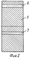
На фиг.2 - общий вид керамического основания. Figure 2 is a General view of the ceramic base.
На фиг.3 - общий вид изготовленного электродного блока. Figure 3 is a General view of the manufactured electrode unit.
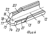
На фиг. 4 - аксонометрическое изображение предлагаемого инструмента с разрезом. In FIG. 4 - axonometric image of the proposed tool with a slit.
На фиг.1-4 приняты следующие обозначения:
1 - заготовка внешнего электрода,
2 - наружная цилиндрическая поверхность заготовки 1,
3 - плоская торцевая поверхность заготовки 1,
4 - сферическая рабочая поверхность заготовки 1,
5 - керамическое основание,
6, 7 - отверстия под выводы электродов,
8 - промежуточная прослойка для диффузионной сварки,
9 - внутренний электрод,
10 - кольцевая канавка,
11 - ось заготовки,
12 - держак инструмента,
13 - рабочая часть инструмента,
14 - продольный уступ режущей части,
15 - спиральная торцевая поверхность,
16 - подножье уступа,
17 - режущая кромка,
18 - плоская поверхность уступа,
19 - ось трубы,
20 - внутренний конус трубы,
21 - наружный конус трубы,
22, 23 - линии пересечения конических поверхностей 20 и 21 с торцевой плоскостью 15,
24, 25 - выводы электродов,
d - максимальный диаметр канавки.Figure 1-4 adopted the following notation:
1 - blank external electrode,
2 - the outer cylindrical surface of the workpiece 1,
3 - flat end surface of the workpiece 1,
4 - spherical working surface of the workpiece 1,
5 - ceramic base
6, 7 - holes for the conclusions of the electrodes,
8 - an intermediate layer for diffusion welding,
9 - internal electrode,
10 - annular groove,
11 - the axis of the workpiece,
12 - tool holder,
13 - the working part of the tool,
14 is a longitudinal ledge of the cutting part,
15 - spiral end surface,
16 - foot of the ledge,
17 - cutting edge,
18 is a flat surface of the ledge,
19 - axis of the pipe,
20 - inner cone of the pipe,
21 - the outer cone of the pipe,
22, 23 - the intersection lines of the
24, 25 - conclusions of the electrodes,
d is the maximum diameter of the groove.
Предлагаемый способ включает в себя следующую последовательность технологических операций:
1. Выполнение заготовки 1 внешнего электрода с наружной цилиндрической поверхностью 2 в виде массивного элемента (фиг.1).The proposed method includes the following sequence of technological operations:
1. The workpiece 1 of the outer electrode with the outer cylindrical surface 2 in the form of a massive element (figure 1).
2. Выполнение на этом этапе плоской торцевой поверхности 3. 2. The implementation at this stage of a flat end surface 3.
3. Выполнение сферической рабочей поверхности 4 на другом торце заготовки 1. 3. The implementation of the spherical working surface 4 on the other end of the workpiece 1.
4. Изготовление керамического основания 5 (фиг.2) в виде массивного цилиндра с двумя отверстиями 6 и 7. 4. The manufacture of ceramic base 5 (figure 2) in the form of a massive cylinder with two
5. Жесткое закрепление заготовки 1 внешнего электрода на керамическом основании 5 посредством диффузионной сварки (например, через промежуточную прослойку, которая на фиг.3 обозначена жирной линией и цифрой 8). 5. Rigid fastening of the workpiece 1 of the external electrode to the
6. Формирование внутреннего электрода сквозной проточкой кольцевой канавки 10 массива заготовки 1 внешнего электрода со стороны, противоположной основанию 5. Ось симметрии канавки 10 совпадает с осью 11 заготовки 1 внешнего электрода. Проточку выполняют инструментом, изображенным на фиг.4. 6. The formation of the inner electrode through the groove of the
Предлагаемый инструмент содержит:
1. Держак 12, т.е. цилиндрическую часть инструмента, которая является зоной крепления инструмента на станке (она может быть массивной).The proposed tool contains:
1.
2. Рабочую часть 13 в виде трубы. 2. The working
3. Режущую часть, выполненную продольным уступом 14 стенки трубы, с торцевой поверхностью 15 в виде спирали, один конец которой совпадает с подножьем 16 уступа, а второй - с режущей кромкой 17, образованной ее пересечением с плоской поверхностью 18 уступа 14. Плоская поверхность 18 уступа 14 параллельна оси 19 трубы. 3. The cutting part made by a
Поверхность спирали ограничена (пересекается), с одной стороны, с наружной поверхностью трубы, с другой - с ее внутренней поверхностью. The surface of the spiral is limited (intersects), on the one hand, with the outer surface of the pipe, on the other - with its inner surface.
Внутренняя поверхность трубы образована (начиная с ее торца) конусом 20, ориентированным большим основанием в сторону, противоположную режущей части (т.е. в сторону держака 12). The inner surface of the pipe is formed (starting from its end) by a
Наружная поверхность трубы образована конусом 21, т.е. в сторону держака 12 обращено меньшее основание. The outer surface of the pipe is formed by a
Обе конические поверхности пересекаются с торцевой поверхностью 15 трубы (линии пересечения - это линии 22 и 23, ограничивающие ленту спирали с боков). Спираль торцевой поверхности 15 имеет шаг в пределах рабочей части 13. Both conical surfaces intersect with the
Конуса 20 и 21 выполнены на всей длине рабочей части 13, которая определяет фактически максимально возможную глубину проточки. The
Предлагаемый инструмент не может быть отнесен к сверлам, так как у него режущая часть не симметрична относительно оси 19. Однако это и не токарный резец, так как рабочая часть 13 выполнена в виде трубы, что не характерно для резцов. Продольная подача (вдоль оси 19) не может быть большой, т.к. образующаяся при этом стружка скапливается между спиральными торцом режущей части и дном протачиваемой канавки 10. Конуса 20 и 21 обеспечивают свободный вход и выход инструмента в протачиваемую канавку 10 даже в условиях, когда стружка попадает между стенками канавки 10 и стенками рабочей части 13 инструмента. Без этих конусов инструмент не работоспособен. The proposed tool cannot be attributed to drills, since its cutting part is not symmetrical about
Спиральный торец обеспечивает:
1. Максимальную жесткость режущей части на изгиб (т.е. максимальную прочность инструмента).The spiral end provides:
1. Maximum bending stiffness of the cutting part (ie maximum tool strength).
2. Наибольшую емкость пазухи под режущей частью для скапливания стружки. 2. The largest sinus capacity under the cutting part for the accumulation of chips.
Без выполнения спирального торца инструмент не работоспособен. Работу нужно осуществлять периодическим введением инструмента в канавку 10 с малой подачей при разрезании, затем полный выход инструмента из канавки 10 для удаления стружки. Затем повторение операций. Without a spiral end, the tool is not operational. The work must be carried out by periodically introducing the tool into the
Инструмент позволяет выполнить канавку шириной 0,4-0,6 мм при глубине в пределах 10-12 мм (максимальный диаметр d канавки (фиг.3) в пределах 5 мм. Ни один из известных инструментов не обеспечивает выполнение такой операции. The tool allows you to make a groove with a width of 0.4-0.6 mm with a depth in the range of 10-12 mm (maximum diameter d of the groove (figure 3) within 5 mm. None of the known tools provides such an operation.
Таким образом, предлагаемый способ изготовления электродного блока может быть осуществлен только при наличии предлагаемого инструмента. Thus, the proposed method for manufacturing the electrode block can be carried out only in the presence of the proposed tool.
По сравнению с прототипом предлагаемые технические решения обеспечивают повышение точности изготовления электродного блока. Compared with the prototype, the proposed technical solutions provide increased accuracy in the manufacture of the electrode block.
Это обусловлено тем, что предлагаемым способом электродный блок изготавливается как одна деталь, т.е. в нем не может быть:
1. Несовпадения центров сферических поверхностей двух электродов между собой.This is due to the fact that the proposed method, the electrode block is made as one part, i.e. it cannot be:
1. Mismatches of the centers of the spherical surfaces of the two electrodes with each other.
2. Несовпадения осей электродов. 2. Mismatch of the axes of the electrodes.
3. Эксцентриситета между собой цилиндрических стенок канавки 10, разделяющей электроды. 3. The eccentricity between the cylindrical walls of the
Более того, выполнение блока позволяет уменьшить градиент электрического поля между электродами и в рабочем зазоре. Это увеличит точность гироскопа и повысит его надежность, т.к. нижняя граница пробойного напряжения, определяемая градиентом электрического поля, возрастает. Moreover, the implementation of the block allows you to reduce the gradient of the electric field between the electrodes and in the working gap. This will increase the accuracy of the gyroscope and increase its reliability, as the lower limit of the breakdown voltage, determined by the gradient of the electric field, increases.
На предприятии ЦНИИ "Электроприбор" предлагаемые технические решения реализованы. При их испытаниях получены положительные результаты. В настоящее время разрабатывается техническая документация для применения предлагаемых решений при производстве малогабаритных электростатических гироскопов. At the TsNII Elektribribor enterprise, the proposed technical solutions are implemented. During their testing, positive results were obtained. Currently, technical documentation is being developed for the application of the proposed solutions in the production of small-sized electrostatic gyroscopes.
Технико-экономическая эффективность изобретения заключается в повышении точности и надежности малогабаритных электростатических гироскопов. Feasibility of the invention is to improve the accuracy and reliability of small-sized electrostatic gyroscopes.
В связи с отсутствием сведений о потребностях страны в таких гироскопах, экономический эффект изобретения подсчитать не представляется возможным. Due to the lack of information about the country's needs for such gyroscopes, it is not possible to calculate the economic effect of the invention.
Claims (2)
Priority Applications (1)
| Application Number | Priority Date | Filing Date | Title |
|---|---|---|---|
| RU2001128102A RU2202103C1 (en) | 2001-10-16 | 2001-10-16 | Method for producing electrode unit of electrostatic gyroscope gyro camera and tool for producing electrode unit of electrostatic gyroscope gyro camera |
Applications Claiming Priority (1)
| Application Number | Priority Date | Filing Date | Title |
|---|---|---|---|
| RU2001128102A RU2202103C1 (en) | 2001-10-16 | 2001-10-16 | Method for producing electrode unit of electrostatic gyroscope gyro camera and tool for producing electrode unit of electrostatic gyroscope gyro camera |
Publications (1)
| Publication Number | Publication Date |
|---|---|
| RU2202103C1 true RU2202103C1 (en) | 2003-04-10 |
Family
ID=20253790
Family Applications (1)
| Application Number | Title | Priority Date | Filing Date |
|---|---|---|---|
| RU2001128102A RU2202103C1 (en) | 2001-10-16 | 2001-10-16 | Method for producing electrode unit of electrostatic gyroscope gyro camera and tool for producing electrode unit of electrostatic gyroscope gyro camera |
Country Status (1)
| Country | Link |
|---|---|
| RU (1) | RU2202103C1 (en) |
Cited By (1)
| Publication number | Priority date | Publication date | Assignee | Title |
|---|---|---|---|---|
| RU2238249C2 (en) * | 2003-03-21 | 2004-10-20 | Открытое акционерное общество Арзамасское научно-производственное предприятие "Темп-Авиа" | Method of hermetically joining glass ceramics with metallic part |
Citations (3)
| Publication number | Priority date | Publication date | Assignee | Title |
|---|---|---|---|---|
| SU618202A1 (en) * | 1976-07-12 | 1978-07-17 | Предприятие П/Я В-2769 | Cutting-tool |
| WO1996012592A1 (en) * | 1994-10-23 | 1996-05-02 | Iscar Ltd. | Cutting tool assembly having an exchangeable adaptor |
| RU2127868C1 (en) * | 1996-06-26 | 1999-03-20 | Центральный научно-исследовательский институт "Электроприбор" | Process of manufacture of electrode system on spherical surface of vacuum chamber of electrostatic gyroscope |
-
2001
- 2001-10-16 RU RU2001128102A patent/RU2202103C1/en not_active IP Right Cessation
Patent Citations (3)
| Publication number | Priority date | Publication date | Assignee | Title |
|---|---|---|---|---|
| SU618202A1 (en) * | 1976-07-12 | 1978-07-17 | Предприятие П/Я В-2769 | Cutting-tool |
| WO1996012592A1 (en) * | 1994-10-23 | 1996-05-02 | Iscar Ltd. | Cutting tool assembly having an exchangeable adaptor |
| RU2127868C1 (en) * | 1996-06-26 | 1999-03-20 | Центральный научно-исследовательский институт "Электроприбор" | Process of manufacture of electrode system on spherical surface of vacuum chamber of electrostatic gyroscope |
Non-Patent Citations (1)
| Title |
|---|
| ОСОКИН Ю.А. и др. Теория и применение электромагнитных подвесов. - М.: Машиностроение, 1980, с. 264, рис. 8.22. Справочник инструментальщика. /Под общей ред. ОРДИНАРЦЕВА И.А. - Л.: Машиностроение, Ленинградское отделение, 1987, с.378-379, рис. 10, 11. * |
Cited By (1)
| Publication number | Priority date | Publication date | Assignee | Title |
|---|---|---|---|---|
| RU2238249C2 (en) * | 2003-03-21 | 2004-10-20 | Открытое акционерное общество Арзамасское научно-производственное предприятие "Темп-Авиа" | Method of hermetically joining glass ceramics with metallic part |
Similar Documents
| Publication | Publication Date | Title |
|---|---|---|
| Leo Kumar et al. | A review on current research aspects in tool-based micromachining processes | |
| Egashira et al. | Drilling of microholes down to 10 μm in diameter using ultrasonic grinding | |
| EP0583329B1 (en) | Process for the manufacture of a multipolar elongate-electrode lens or mass filter | |
| Saranya et al. | Fabrication of precise micro-holes on quartz substrates with improved aspect ratio using a constant velocity-feed drilling technique of an ECDM process | |
| RU2202103C1 (en) | Method for producing electrode unit of electrostatic gyroscope gyro camera and tool for producing electrode unit of electrostatic gyroscope gyro camera | |
| Fonda et al. | A study on the optimal fabrication method for micro-scale gyroscopes using a hybrid process consisting of electric discharge machining, chemical etching or micro-mechanical milling | |
| CN114290538A (en) | Method for processing diaphragm hole of cavity of laser gyroscope | |
| US20200122300A1 (en) | Grinding wheel tool for microgroove processing and fabrication method thereof | |
| Pratap et al. | Fabrication of array microelectrodes: achieving geometrical characteristics using reverse micro-EDM process | |
| CN104249310B (en) | Tack cutter and the glass or glass and ceramic product of the tack cutter manufacture can be used | |
| Tong et al. | Servo scanning 3D micro EDM for array micro cavities using on-machine fabricated tool electrodes | |
| CN110355622A (en) | Composite vibration grinding wheel for ultrasonic machining | |
| JP2015085419A (en) | Lapping reamer and manufacturing method of lapping reamer | |
| JP2020049646A (en) | Microfabrication device, microfabrication method, transfer mold, and transfer object | |
| CN114340831B (en) | Stone material, in particular for timepiece movements, and method for manufacturing same | |
| US6766662B2 (en) | Method of manufacturing glass parts for connecting optical fibers, and glass parts for connecting optical fibers manufactured using the methods | |
| KR102124707B1 (en) | A Processing Too1 for a Difficult-to-Cut Material Used in Processing a Helix of Ceramics | |
| CN116038255A (en) | A Processing Method of Miniature Precision Inclined Hole | |
| GB2107626A (en) | Flow-drilling tool | |
| Reynaerts et al. | Production of seismic mass suspensions in silicon by electro-discharge machining | |
| CN113613841A (en) | Cutting tool and method for manufacturing optical fiber preform | |
| RU1794614C (en) | Method for making articles with long channels | |
| CN114139301A (en) | Hemispherical harmonic oscillator machining error standard making method based on frequency cracking | |
| KR101117778B1 (en) | Method for Producing Optical Fiber and Preform | |
| JPS63127865A (en) | Method of working optical connector ferrule |
Legal Events
| Date | Code | Title | Description |
|---|---|---|---|
| HK4A | Changes in a published invention | ||
| MM4A | The patent is invalid due to non-payment of fees |
Effective date: 20181017 |