RU2192508C2 - Busbar structure of electrolytic cell - Google Patents
Busbar structure of electrolytic cell Download PDFInfo
- Publication number
- RU2192508C2 RU2192508C2 RU2000130724/02A RU2000130724A RU2192508C2 RU 2192508 C2 RU2192508 C2 RU 2192508C2 RU 2000130724/02 A RU2000130724/02 A RU 2000130724/02A RU 2000130724 A RU2000130724 A RU 2000130724A RU 2192508 C2 RU2192508 C2 RU 2192508C2
- Authority
- RU
- Russia
- Prior art keywords
- busbar
- electrolytic cell
- main
- supporting
- electrodes
- Prior art date
Links
Images
Classifications
-
- C—CHEMISTRY; METALLURGY
- C25—ELECTROLYTIC OR ELECTROPHORETIC PROCESSES; APPARATUS THEREFOR
- C25C—PROCESSES FOR THE ELECTROLYTIC PRODUCTION, RECOVERY OR REFINING OF METALS; APPARATUS THEREFOR
- C25C7/00—Constructional parts, or assemblies thereof, of cells; Servicing or operating of cells
- C25C7/02—Electrodes; Connections thereof
Abstract
Description
Область техники, к которой относится изобретение
Данное изобретение относится к шинной конструкции электролитической ячейки, предназначенной для электролизного извлечения металлов, выполненной как единое целое таким образом, что межэлектродный зазор, т.е. расстояние, можно свободно подбирать и изменять. Все детали конструкции имеют в электролитической ячейке постоянное поперечное сечение по длине.FIELD OF THE INVENTION
This invention relates to a busbar design of an electrolytic cell designed for electrolytic extraction of metals, made as a unit so that the interelectrode gap, i.e. distance, you can freely select and change. All structural parts have a constant cross-section in length in the electrolytic cell.
Уровень техники
В ваннах, сконструированных для электролизного извлечения металлов, таких как медь, никель и цинк, обычно располагают большое число электролитических ячеек, которые последовательно соединяют в группы, в результате чего анод одной электролитической ячейки электрически соединен с катодом следующей электролитической ячейки с помощью имеющих высокую проводимость шин, выполненных обычно из меди и расположенных на перегородке между ваннами. Устройство такого вида известно под названием системы Уолкера.State of the art
In bathtubs designed for the electrolytic extraction of metals, such as copper, nickel and zinc, a large number of electrolytic cells are usually located, which are connected in series into groups, as a result of which the anode of one electrolytic cell is electrically connected to the cathode of the next electrolytic cell using high conductivity buses usually made of copper and located on the partition between the bathtubs. A device of this kind is known as the Walker system.
Эта конструкция также обычно содержит имеющий вырезы изолирующий стержень, находящийся наверху шины, чтобы отделять катод предшествующей электролитической ячейки и анод последующей электролитической ячейки от шины. Такое устройство обязательно, поскольку все электроды в ваннах в ином случае были бы электрически соединенными и ток в этом случае не протекал бы через электролит. This design also typically includes a cut-out insulating rod located at the top of the busbar to separate the cathode of the preceding electrolytic cell and the anode of the subsequent electrolytic cell from the busbar. Such a device is necessary, since all the electrodes in the baths would otherwise be electrically connected and the current in this case would not flow through the electrolyte.
В шине согласно известному уровню техники боковые стенки обычно имеют утолщения полукруглого или треугольного поперечного сечения, идущие по длине шины; причем утолщения являются либо сплошными, либо, для изолирующей шины, прерывистыми. Электроды, которые должны контактировать с шиной, устанавливают сверху этих утолщений. Назначение утолщений в первую очередь заключается в придании жесткости шине, и, во-вторых, в обеспечении линейного контакта между шиной и электродом. In a tire according to the prior art, the side walls usually have thickenings of a semicircular or triangular cross section extending along the length of the tire; moreover, the bulges are either continuous, or, for the insulating bus, intermittent. The electrodes that must be in contact with the bus are mounted on top of these bulges. The purpose of the thickenings is primarily to stiffen the tire, and, secondly, to provide linear contact between the tire and the electrode.
Изолирующий стержень имеет скобы, направленные в стороны, которые проходят либо между прерывистыми утолщениями шины, или по верху непрерывных утолщений. Электроды, не контактирующие с шиной, устанавливают сверху этих изолирующих скоб. The insulating rod has brackets directed to the sides, which extend either between intermittent thickenings of the tire, or on top of continuous thickenings. Electrodes not in contact with the bus are mounted on top of these insulating brackets.
Известна шинная конструкция, раскрываемая в патенте США 3682809, где в соответствии с Фиг.1 шина выполнена сплошной, при этом опорные выступы электродов имеют вырезы на той стороне, на которой их помещают сверху шины. Согласно этой Фиг. опорные элементы одного и того же электрода изменяются по длине. Но на этой Фиг. не изображено, как электроды двух соседних ванн расположены относительно шины и изолирующего стержня. A tire structure is known, disclosed in US Pat. No. 3,682,809, where, in accordance with FIG. 1, the tire is solid, with the electrode protrusions having cutouts on the side on which they are placed on top of the tire. According to this FIG. supporting elements of the same electrode vary in length. But in this FIG. not shown how the electrodes of two adjacent baths are located relative to the busbar and the insulating rod.
В обычной шинной конструкции с имеющими вырезы электродами всегда есть следующие недостатки:
Электрическое подключение каждого электрода к цепи основано на одном контакте. Поскольку качество контакта (хороший/плохой контакт) сильно изменяется, поэтому токораспределение между электродами неровное.In a conventional busbar design with cut-out electrodes, there are always the following disadvantages:
The electrical connection of each electrode to the circuit is based on one contact. Since the contact quality (good / bad contact) varies greatly, therefore, the current distribution between the electrodes is uneven.
Если используется имеющий вырезы медный стержень, то его себестоимость выше стержня без вырезов. Если, с другой стороны, используется шина без вырезов, то электроды не будут находиться в горизонтальном положении по причине наличия изолирующей шины. If a copper rod having cutouts is used, then its prime cost is higher than the rod without cutouts. If, on the other hand, a tire without cuts is used, then the electrodes will not be in a horizontal position due to the presence of an insulating bus.
Изготовление имеющих вырезы электродов обходится дороже, чем изготовление электродов без вырезов. Making cut-out electrodes is more expensive than making cut-out electrodes.
При введении их в ванну имеющие вырезы электроды надо опускать в электролитическую ячейку по ширине очень осторожно, чтобы соблюсти правильное положение относительно шины. When introducing them into the bath, the cut-out electrodes must be lowered into the electrolytic cell in width very carefully to maintain the correct position relative to the tire.
По причине наличия имеющего вырезы изолирующего стержня и, возможно, медной шины, электроды надо опускать в электролитическую ячейку очень осторожно для соблюдения правильного положения по длине относительно шины в целях правильного формирования электрических контактов и расстояний между электродами. Тепловое удлинение шины может обусловить появление проблем. Due to the presence of cutouts of an insulating rod and possibly a copper bus, the electrodes must be lowered into the electrolytic cell very carefully to maintain the correct position along the length of the bus in order to correctly form electrical contacts and the distances between the electrodes. Thermal lengthening of the tire can cause problems.
Имеющая вырезы шина не позволяет изменять межэлектродный зазор без замены всех шин и изолирующих стержней. Изменение межэлектродного зазора с неимеющей вырезов медной шиной требует замены изолирующих стержней. The cut-out tire does not allow changing the interelectrode gap without replacing all tires and insulating rods. Changing the interelectrode gap with a notched copper bus bar requires replacement of the insulating rods.
По причине наличия имеющего вырезы изолирующего стержня очистка шин на практике всегда требует удаления изолирующего стержня во время очистки. Это значительно затрудняет механическую очистку. Due to the presence of cutouts of an insulating rod, tire cleaning in practice always requires the removal of the insulating rod during cleaning. This greatly complicates mechanical cleaning.
Поскольку имеющая вырезы шина должна быть выполнена относительно тонкой, она обычно очень непрочная и имеет короткий срок службы. Since the cut-out tire must be relatively thin, it is usually very fragile and has a short life.
Сущность изобретения
Задача данного изобретения состоит в создании шинной конструкции, которая устранит упомянутые выше недостатки обычной конструкции. В шинной конструкции согласно данному изобретению имеющую высокую проводимость главную шину устанавливают сверху боковой стенки электролитической ячейки, электрически соединяя аноды предшествующей электролитической ячейки с катодами соседней электролитической ячейки таким образом, что ванны подключаются последовательно обычным образом. Главная шина имеет сплошные боковые утолщения с разной высотой, поэтому один комплект электродов - аноды и катоды - находится в данной электролитической ячейке ниже, чем другой комплект. Опорные элементы также выполняют наверху боковой стенки электролитической ячейки, и на них опираются электроды на той стороне, которая не контактирует с главной шиной. Опорные элементы электрически изолированы от главной шины, и их целесообразно выполнять из электропроводного материала, чтобы они уравновешивали потенциал между электродами одинакового знака полярности в электролитической ячейке. Главная шина, опорные элементы и изолирующие материалы, все из них, расположены вместе продольно относительно электролитической ячейки и имеют постоянные поперечные сечения по всей своей длине. Существенные признаки данного изобретения очевидны из прилагаемой формулы изобретения.SUMMARY OF THE INVENTION
An object of the present invention is to provide a tire structure that eliminates the aforementioned disadvantages of a conventional structure. In the busbar structure of the present invention, a high conductivity main bus is mounted on top of the side wall of the electrolytic cell, electrically connecting the anodes of the previous electrolytic cell to the cathodes of the adjacent electrolytic cell so that the baths are connected in series in a conventional manner. The main busbar has continuous lateral thickenings with different heights, therefore, one set of electrodes - anodes and cathodes - is located in this electrolytic cell lower than the other set. The supporting elements are also performed at the top of the side wall of the electrolytic cell, and electrodes are supported on them on the side that does not contact the main bus. The support elements are electrically isolated from the main bus, and it is advisable to make them from an electrically conductive material so that they balance the potential between the electrodes of the same sign of polarity in the electrolytic cell. The main busbar, supporting elements and insulating materials, all of them, are arranged together longitudinally relative to the electrolytic cell and have constant cross sections along their entire length. The essential features of this invention are apparent from the appended claims.
Боковые утолщения главной шины находятся на разных высотах, в результате чего некоторые электроды, например аноды, находятся несколько ниже в электролитической ячейке, чем другие электроды, например, в этом случае, катоды. На практике и нижнее утолщение главной шины на одной стороне электролитической ячейки, и нижний опорный элемент на другой стороне электролитической ячейки находятся ближе к осевой линии электролитической ячейки, чем более высокие аналогичные элементы, причем опорные выступы электродов, расположенных ниже, выполнены более короткими, чем те выступы электродов, которые расположены выше; а верхнее утолщение и опорный элемент расположены вблизи осевой линии стенки электролитической ячейки; при этом они располагаются дальше от осевой линии самой электролитической ячейки, чем аналогичные нижние элементы. При необходимости эту компоновку можно выполнить наоборот, т. е. можно расположить катоды на нижних утолщениях, а аноды - на верхних. Утолщения главной шины являются сплошными и не имеют на них изолирующих скоб. Термины "сплошной" или "целый" используют для обозначения того, что данный материал не имеет вырезов для размещения электродов и что данный материал по существу имеет одинаковую прочность по длине электролитической ячейки. Опорные выступы электродов также не имеют вырезов. Lateral thickenings of the main bus are at different heights, as a result of which some electrodes, for example anodes, are somewhat lower in the electrolytic cell than other electrodes, for example, in this case, cathodes. In practice, both the lower thickening of the main busbar on one side of the electrolytic cell and the lower supporting element on the other side of the electrolytic cell are closer to the center line of the electrolytic cell than the higher similar elements, and the supporting protrusions of the electrodes located lower are shorter than those protrusions of the electrodes that are located above; and the upper thickening and supporting element are located near the center line of the wall of the electrolytic cell; however, they are located farther from the centerline of the electrolytic cell itself than similar lower cells. If necessary, this arrangement can be performed vice versa, i.e., cathodes can be located on the lower bulges, and the anodes on the upper ones. The thickenings of the main tire are continuous and do not have insulating brackets on them. The terms “solid” or “whole” are used to mean that the material does not have cutouts for the placement of electrodes and that the material has essentially the same strength along the length of the electrolytic cell. The supporting protrusions of the electrodes also have no cutouts.
Опорный элемент верхних электродов помещен наверху главной шины между ее утолщениями. Опорным элементом наиболее целесообразно является уравнивающий потенциал стержень, отделяемый от главной шины изолирующим материалом. Как стержень, так и изолирующий материал имеют постоянные поперечные сечения по своей длине. Этот стержень находится на том же уровне, что и верхнее утолщение главной шины, и формирует электрическое соединение между опорными выступами верхних электродов, которые не находятся на главной шине. The support element of the upper electrodes is placed at the top of the main bus between its thickenings. The supporting element is most expediently a potential equalizing rod, which is separated from the main tire by an insulating material. Both the core and the insulating material have constant cross sections along their length. This rod is at the same level as the upper bulge of the main bus, and forms an electrical connection between the supporting protrusions of the upper electrodes, which are not on the main bus.
Опорный элемент нижних электродов, который также предпочтительно является уравнивающим потенциал стержнем, находится на наружной стороне главной шины, рядом с ее верхним утолщением по краю электролитической ячейки и сверху изолирующего материала. И стержень, и изолирующий материал имеют постоянные поперечные сечения по своей длине. Этот стержень находится на том же уровне, что и нижнее утолщение главной шины, и формирует электрическое соединение между опорными утолщениями нижних электродов, которые не находятся на главной шине. Изоляция ниже этого уравнивающего потенциал стержня может быть выполнена в нем между главной шиной и боковой стенкой электролитической ячейки. The support element of the lower electrodes, which is also preferably a potential equalizing rod, is located on the outside of the main bus, near its upper bulge along the edge of the electrolytic cell and on top of the insulating material. Both the core and the insulating material have constant cross sections along their length. This rod is at the same level as the lower bulge of the main bus, and forms an electrical connection between the supporting bulges of the lower electrodes that are not on the main bus. Insulation below this potential equalizing rod can be made in it between the main busbar and the side wall of the electrolytic cell.
По сравнению с известным уровнем техники выполнение шины согласно данному изобретению дает по меньшей мере следующие преимущества:
И главная шина, и уравновешивающие потенциал стержни, и также изолирующие профили не имеют вырезов и имеют постоянные поперечные сечения, в результате чего распределение электродов можно свободно изменять без необходимости что-либо делать с шиной.Compared with the prior art, the implementation of the tire according to this invention provides at least the following advantages:
Both the main bus and the potential-balancing rods, as well as the insulating profiles, do not have cutouts and have constant cross sections, as a result of which the distribution of the electrodes can be freely changed without having to do anything with the bus.
Проста механическая очистка шин, поскольку все очищаемые поверхности являются сплошными и выполнены из одного материала. Нет необходимости разбирать шинную конструкцию для очистки. Mechanical tire cleaning is easy, as all surfaces to be cleaned are solid and made of the same material. There is no need to disassemble the busbar structure for cleaning.
Шинная конструкция прочная и долговечная. The tire structure is strong and durable.
Благодаря уравнивающему потенциал стержню каждый электрод теперь имеет два контакта с электрической цепью: если один электрод имеет контакт с главной шиной, который хуже среднего, то параллельные электроды выравнивают токораспределение с помощью уравновешивающего потенциал стержня для обеспечения более ровного токораспределения. Thanks to the potential equalizing rod, each electrode now has two contacts with the electric circuit: if one electrode has a contact with the main bus that is worse than the average, then the parallel electrodes equalize the current distribution with the help of the potential balancing rod to ensure a more even current distribution.
Электроды всегда можно выпрямить. The electrodes can always be straightened.
Электрические контакты и разделители всегда формируются правильно, даже если электроды не опущены в ванны тщательно в требуемое место поперечно и продольно относительно шины. Тепловое расширение шины проблем не вызывает. Electrical contacts and dividers are always formed correctly, even if the electrodes are not lowered into the baths carefully to the desired location transversely and longitudinally with respect to the tire. Thermal expansion of the bus does not cause problems.
Перечень фигур чертежей
Данное изобретение более точно иллюстрируется в прилагаемых чертежах, где Фиг.1 представляет поперечное сечение электролитической ячейки с шинной конструкцией в соответствии с данным изобретением и Фиг.2 представляет более подробное изображение шинной конструкции.List of drawings
The invention is more precisely illustrated in the accompanying drawings, in which Fig. 1 is a cross-sectional view of an electrolytic cell with a busbar structure in accordance with this invention and Fig. 2 is a more detailed depiction of a busbar structure.
Сведения, подтверждающие возможность осуществления изобретения
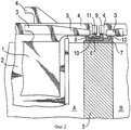
Согласно Фиг.1 аноды и катоды опущены в электролитическую ячейку А и также в электролитическую ячейку В, причем на Фиг.1 видны только их опорные выступы. Согласно Фиг.1 анод 1, на переднем плане, расположен ниже катода 2, изображаемого на заднем плане. Как обычно, аноды и катоды расположены в электролитической ячейке попеременно. И аноды, и катоды опираются посредством опорных выступов 3 и 4 на шинную конструкцию, согласно данному изобретению расположенную на боковых стенках 5 электролитической ячейки. Боковая стенка означает боковую стенку между двумя соседними ваннами - независимо от выполнения ее из одной или более прилегающих друг к другу частей.Information confirming the possibility of carrying out the invention
According to FIG. 1, the anodes and cathodes are lowered into the electrolytic cell A and also into the electrolytic cell B, wherein in FIG. 1 only their supporting projections are visible. 1, the
Фиг. 2 более подробно изображает, как главная шина 6 помещена сверху изолирующей пластины 7, которая находится на боковой стенке 5. Применение изолирующей пластины под главной шиной не является обязательным, но рекомендуется из практических соображений. Основная шина проходит по верху боковых стенок по всей длине электролитической ячейки. Нижняя поверхность главной шины горизонтальная и может быть также центром верхней поверхности, но на краях шины два сплошных утолщения, или гребня, разной высоты поднимаются и выступают вверх в продольном направлении. Утолщения могут иметь разную форму, но, например, утолщение полукруглого сечения является целесообразным. В случае Фиг.2 опорные выступы 3 анодов в электролитической ячейке А помещены на нижнем утолщении 8, а опорные выступы 4 катодов в электролитической ячейке В находятся сверху более высокого утолщения 9. Не имея вырезов, нижний край опорных выступов электродов является сплошным. Соответствующей разницей высоты выступов является обычно разница в 5-15 мм; и для практических целей аноды часто выбирают в качестве более низких электродов. Целесообразно размещать нижнее утолщение ближе к краю электролитической ячейки, а верхнее утолщение - вблизи центра боковой стенки. FIG. 2 depicts in more detail how the
Сплошной изолирующий профиль 10 помещен между утолщениями 8 и 9 главной шины 6 по всей длине шины и сверху профиля находится опорный элемент 11 катодов электролитической ячейки А. Этот опорный элемент в этом случае является электропроводным уравнивающим потенциал стержнем. Поскольку опорные выступы катодов в другой стороне электролитической ячейки А (не изображено) опираются на верхнее утолщение главной шины в следующей электролитической ячейке, поэтому верхняя часть уравнивающего потенциал стержня 11 установлена на той же высоте, что и верхнее утолщение главной шины, в результате чего катоды имеют горизонтальное положение на своих опорных выступах 4. A continuous insulating
Согласно Фиг. 2 главная шина 6 не проходит по всей ширине края электролитической ячейки, и часть края покрыта только изолирующей пластиной 7. Опорный элемент 12 анодов в электролитической ячейке В в этом случае - также уравнивающий потенциал стержень, наиболее целесообразно размещать на той части изолирующей пластины, которая находится снаружи главной шины, и таким образом опорный элемент соединяет опорные выступы анода, которые не опираются на главную шину. Этот опорный элемент установлен на такой высоте, что он поднимает опорные выступы 3 другого конца анодов на ту же высоту, что и опорные выступы на главной шине. Ни на том, ни на другом уравновешивающих потенциал стержнях изолирующего материала нет. Стержни предпочтительно выполняют из одного и того же материала, например из прутка круглого или треугольного поперечного сечения. According to FIG. 2, the
Если в отношении тех или других электродов, анодов или катодов нежелательно использование уравновешивающего потенциал стержня, то этот стержень можно заменить соответствующим образом выполненным профилем из изолирующего материала, либо возможно изолирующий материал сформировать непосредственно таким образом, что на него будут опираться опорные выступы электродов на правильной высоте. Но в этом случае некоторые из упоминаемых выше преимуществ будут потеряны. If in relation to one or another electrode, anode or cathode, it is undesirable to use a counterbalancing rod, then this rod can be replaced with a suitably made profile of insulating material, or it is possible to form the insulating material directly so that the electrode support projections rest on it at the correct height . But in this case, some of the benefits mentioned above will be lost.
Как указывалось выше, главная шина не проходит по всей ширине боковых стенок электролитической ячейки, а несколько превышает половину ширины боковой стенки. Наиболее оптимально, чтобы оба опорных элемента электродов находились на приблизительно равном расстоянии от осевой линии боковой стенки как соответствующее утолщение главной шины. As indicated above, the main busbar does not extend across the entire width of the side walls of the electrolytic cell, but slightly exceeds half the width of the side wall. It is most optimal for both supporting elements of the electrodes to be approximately equal to the distance from the center line of the side wall as a corresponding thickening of the main busbar.
Claims (11)
Applications Claiming Priority (2)
| Application Number | Priority Date | Filing Date | Title |
|---|---|---|---|
| FI980999 | 1998-05-06 | ||
| FI980999A FI104839B (en) | 1998-05-06 | 1998-05-06 | Current rail construction for an electrolysis pool |
Publications (2)
| Publication Number | Publication Date |
|---|---|
| RU2192508C2 true RU2192508C2 (en) | 2002-11-10 |
| RU2000130724A RU2000130724A (en) | 2003-02-10 |
Family
ID=8551661
Family Applications (1)
| Application Number | Title | Priority Date | Filing Date |
|---|---|---|---|
| RU2000130724/02A RU2192508C2 (en) | 1998-05-06 | 1999-04-21 | Busbar structure of electrolytic cell |
Country Status (18)
| Country | Link |
|---|---|
| US (1) | US6342136B1 (en) |
| EP (1) | EP1095175B1 (en) |
| JP (1) | JP4377056B2 (en) |
| KR (1) | KR100617925B1 (en) |
| CN (1) | CN1204299C (en) |
| AT (1) | ATE310112T1 (en) |
| AU (1) | AU753891B2 (en) |
| BG (1) | BG63896B1 (en) |
| BR (1) | BR9910244A (en) |
| CA (1) | CA2329711C (en) |
| DE (1) | DE69928406T2 (en) |
| ES (1) | ES2251188T3 (en) |
| FI (1) | FI104839B (en) |
| PE (1) | PE20000437A1 (en) |
| PL (1) | PL192738B1 (en) |
| RU (1) | RU2192508C2 (en) |
| WO (1) | WO1999057337A1 (en) |
| ZA (1) | ZA200005904B (en) |
Families Citing this family (21)
| Publication number | Priority date | Publication date | Assignee | Title |
|---|---|---|---|---|
| FI113280B (en) | 2002-04-03 | 2004-03-31 | Outokumpu Oy | Useful displacement and insulation device for electrolysis |
| US7204919B2 (en) * | 2003-12-03 | 2007-04-17 | Pultrusion Technique Inc. | Capping board with at least one sheet of electrically conductive material embedded therein |
| DE102004008813B3 (en) * | 2004-02-20 | 2005-12-01 | Outokumpu Oyj | Process and installation for the electrochemical deposition of copper |
| CA2472688C (en) * | 2004-06-29 | 2011-09-06 | Pultrusion Technique Inc. | Capping board with separating walls |
| CA2676373C (en) * | 2007-01-29 | 2016-03-29 | Pultrusion Technique Inc. | Capping board section and assembly with reinforced mating projection |
| CA2579459C (en) | 2007-02-22 | 2013-12-17 | Pultrusion Technique Inc. | Contact bar for capping board |
| CN101849039B (en) * | 2007-07-31 | 2013-04-10 | 恩克泰克敏股份公司 | System for monitoring, control and management of a plant where hydrometallurgical electrowinning and electrorefining processes for non ferrous metals are conducted |
| US7993501B2 (en) * | 2007-11-07 | 2011-08-09 | Freeport-Mcmoran Corporation | Double contact bar insulator assembly for electrowinning of a metal and methods of use thereof |
| FI121472B (en) | 2008-06-05 | 2010-11-30 | Outotec Oyj | Method for Arranging Electrodes in the Electrolysis Process, Electrolysis System and Method Use, and / or System Use |
| GB2474054A (en) * | 2009-10-02 | 2011-04-06 | Corner Electrical Systems Ltd G | A shorting frame for an electrowinning plant |
| FI121886B (en) * | 2009-10-22 | 2011-05-31 | Outotec Oyj | The busbar structure |
| CN101805911B (en) * | 2010-03-18 | 2012-06-20 | 上海心尔新材料科技股份有限公司 | Energy-saving and environmental-friendly electrolysis system |
| US8597477B2 (en) * | 2011-02-16 | 2013-12-03 | Freeport-Mcmoran Corporation | Contact bar assembly, system including the contact bar assembly, and method of using same |
| US9234287B2 (en) | 2011-07-12 | 2016-01-12 | Pultrusion Technique Inc. | Contact bar and capping board for supporting symmetrical electrodes for enhanced electrolytic refining of metals |
| CL2011002307A1 (en) * | 2011-09-16 | 2014-08-22 | Vargas Aldo Ivan Labra | System composed of an anode hanger means and an anode, which makes it possible to reuse said anode hanger means minimizing scrap production, because said hanger means is formed by a reusable central bar to be located at the top edge of the anode. |
| PE20151177A1 (en) | 2013-01-11 | 2015-08-24 | Pultrusion Tech Inc | SET OF SEGMENTED LEVELING TABLE AND CONTACT BAR, AND METHODS IN HYDROMETALLURGICAL REFINING |
| FI125515B (en) | 2013-03-01 | 2015-11-13 | Outotec Oyj | Method for measuring electric current flowing in an individual electrode in an electrolysis system and arrangement for the same |
| FI125211B (en) | 2013-03-01 | 2015-07-15 | Outotec Oyj | A method of measuring and arranging an electric current flowing at a single electrode of an electrolysis system |
| MX2015016781A (en) | 2013-06-04 | 2016-03-31 | Pultrusion Tech Inc | Configurations and positioning of contact bar segments on a capping board for enhanced current density homogeneity and/or short circuit reduction. |
| EP3283670A4 (en) * | 2015-04-17 | 2019-01-02 | Pultrusion Technique Inc. | Components, assemblies and methods for distributing electrical current in an electrolytic cell |
| WO2021159086A1 (en) * | 2020-02-07 | 2021-08-12 | University Of Kentucky Research Foundation | Electrowinning cells for the segregation of the cathodic and anodic compartments |
Family Cites Families (5)
| Publication number | Priority date | Publication date | Assignee | Title |
|---|---|---|---|---|
| US3682809A (en) * | 1970-02-24 | 1972-08-08 | Kennecott Copper Corp | Electrolytic cell constructed for high circulation and uniform flow of electrolyte |
| US3697404A (en) * | 1971-01-29 | 1972-10-10 | Peter M Paige | Apparatus to support the electrodes and bus bars in an electrolytic cell |
| US3929614A (en) * | 1974-02-19 | 1975-12-30 | Mitsui Mining & Smelting Co | Electrolytic cell having means for supporting the electrodes on the cell wall and means for shorting out the electrodes |
| CA1034533A (en) | 1974-11-28 | 1978-07-11 | Ronald N. Honey | Contact bar for electrolytic cells |
| JP3160556B2 (en) * | 1997-06-20 | 2001-04-25 | 日鉱金属株式会社 | Structure of electrical contact part of electrolytic cell |
-
1998
- 1998-05-06 FI FI980999A patent/FI104839B/en not_active IP Right Cessation
-
1999
- 1999-04-21 CA CA002329711A patent/CA2329711C/en not_active Expired - Lifetime
- 1999-04-21 ES ES99916937T patent/ES2251188T3/en not_active Expired - Lifetime
- 1999-04-21 KR KR1020007012212A patent/KR100617925B1/en not_active IP Right Cessation
- 1999-04-21 DE DE69928406T patent/DE69928406T2/en not_active Expired - Lifetime
- 1999-04-21 WO PCT/FI1999/000324 patent/WO1999057337A1/en active IP Right Grant
- 1999-04-21 RU RU2000130724/02A patent/RU2192508C2/en active
- 1999-04-21 BR BR9910244-7A patent/BR9910244A/en not_active IP Right Cessation
- 1999-04-21 AT AT99916937T patent/ATE310112T1/en not_active IP Right Cessation
- 1999-04-21 CN CNB998058580A patent/CN1204299C/en not_active Expired - Lifetime
- 1999-04-21 PL PL343843A patent/PL192738B1/en not_active IP Right Cessation
- 1999-04-21 US US09/674,124 patent/US6342136B1/en not_active Expired - Lifetime
- 1999-04-21 AU AU35243/99A patent/AU753891B2/en not_active Expired
- 1999-04-21 EP EP99916937A patent/EP1095175B1/en not_active Expired - Lifetime
- 1999-04-21 JP JP2000547285A patent/JP4377056B2/en not_active Expired - Lifetime
- 1999-04-28 PE PE1999000350A patent/PE20000437A1/en not_active IP Right Cessation
-
2000
- 2000-10-23 ZA ZA200005904A patent/ZA200005904B/en unknown
- 2000-11-02 BG BG104906A patent/BG63896B1/en unknown
Also Published As
| Publication number | Publication date |
|---|---|
| KR100617925B1 (en) | 2006-08-30 |
| CA2329711C (en) | 2006-07-11 |
| EP1095175B1 (en) | 2005-11-16 |
| ATE310112T1 (en) | 2005-12-15 |
| BR9910244A (en) | 2001-01-09 |
| PL343843A1 (en) | 2001-09-10 |
| CA2329711A1 (en) | 1999-11-11 |
| AU753891B2 (en) | 2002-10-31 |
| EP1095175A1 (en) | 2001-05-02 |
| FI980999A (en) | 1999-11-07 |
| KR20010043261A (en) | 2001-05-25 |
| DE69928406D1 (en) | 2005-12-22 |
| CN1204299C (en) | 2005-06-01 |
| FI980999A0 (en) | 1998-05-06 |
| FI104839B (en) | 2000-04-14 |
| BG104906A (en) | 2001-07-31 |
| PE20000437A1 (en) | 2000-05-22 |
| JP2002513859A (en) | 2002-05-14 |
| US6342136B1 (en) | 2002-01-29 |
| PL192738B1 (en) | 2006-12-29 |
| JP4377056B2 (en) | 2009-12-02 |
| AU3524399A (en) | 1999-11-23 |
| ZA200005904B (en) | 2001-06-28 |
| DE69928406T2 (en) | 2006-04-20 |
| ES2251188T3 (en) | 2006-04-16 |
| WO1999057337A1 (en) | 1999-11-11 |
| BG63896B1 (en) | 2003-05-30 |
| CN1299421A (en) | 2001-06-13 |
Similar Documents
| Publication | Publication Date | Title |
|---|---|---|
| RU2192508C2 (en) | Busbar structure of electrolytic cell | |
| RU2000130724A (en) | TIRE DESIGN OF THE ELECTROLYTIC CELL | |
| JP6737797B2 (en) | Cathode current collector for Hall-Eru cell | |
| FI75873C (en) | ISOLATOR FOER ANVAENDNING I ELEKTROLYTISKA CELLER. | |
| PL90063B1 (en) | ||
| US4396483A (en) | Arrangement of busbars for electrolytic reduction cells | |
| EA021254B1 (en) | Busbar construction | |
| RU2303657C2 (en) | Bus-bars of aluminum cells arranged crosswise in housing | |
| MXPA00010699A (en) | Busbar construction for electrolytic cell | |
| US3969216A (en) | Flotation separation | |
| CN217203026U (en) | Main and auxiliary electric conduction device between electrolytic and electrodeposition cells | |
| US1815078A (en) | Electrolytic cell | |
| SU703605A1 (en) | Current supply to electrolyzer electrodes | |
| CN115491741A (en) | Anode box and electroplating device | |
| RU2319794C2 (en) | Electric current supply unit for electrodes of electrolyzer | |
| RU99109373A (en) | ELECTROLYZER TIRE FOR ALUMINUM PRODUCTION | |
| WO2024000065A1 (en) | A capping board including side wall portions for preventing metal dust release during electrorefining | |
| CA2923906C (en) | Configurations and positioning of contact bar segments on a capping board for enhanced current density homogeneity and/or short circuit reduction | |
| JP3220094B2 (en) | Connection method of electrolytic cell conductor |