RU2185526C1 - Method of creating thrust in vacuum and field engine for spacecraft (versions) - Google Patents
Method of creating thrust in vacuum and field engine for spacecraft (versions) Download PDFInfo
- Publication number
- RU2185526C1 RU2185526C1 RU2001113320/06A RU2001113320A RU2185526C1 RU 2185526 C1 RU2185526 C1 RU 2185526C1 RU 2001113320/06 A RU2001113320/06 A RU 2001113320/06A RU 2001113320 A RU2001113320 A RU 2001113320A RU 2185526 C1 RU2185526 C1 RU 2185526C1
- Authority
- RU
- Russia
- Prior art keywords
- field
- magnetic
- electric
- vacuum
- spacecraft
- Prior art date
Links
Images

Classifications
-
- F—MECHANICAL ENGINEERING; LIGHTING; HEATING; WEAPONS; BLASTING
- F03—MACHINES OR ENGINES FOR LIQUIDS; WIND, SPRING, OR WEIGHT MOTORS; PRODUCING MECHANICAL POWER OR A REACTIVE PROPULSIVE THRUST, NOT OTHERWISE PROVIDED FOR
- F03H—PRODUCING A REACTIVE PROPULSIVE THRUST, NOT OTHERWISE PROVIDED FOR
- F03H99/00—Subject matter not provided for in other groups of this subclass
Abstract
Description
Изобретение относится к космической отрасли и предназначено для создания тяги в новых поколениях межпланетных космических кораблей за счет использования сверхсильных взаимодействий с вакуумным полем. Изобретения также может быть использовано в народном хозяйстве как энергетическое и тяговое средство для самолета, автомобиля, трактора и других транспортных средств. The invention relates to the space industry and is intended to create thrust in new generations of interplanetary spacecraft through the use of ultra-strong interactions with a vacuum field. The invention can also be used in the national economy as an energy and traction tool for an airplane, automobile, tractor and other vehicles.
Известен способ создания реактивной тяги в вакууме за счет истечения газов через реактивное сопло в результате сжигания химического топлива в реактивном двигателе (статьи "Реактивная тяга" и "Реактивный двигатель". Политехнический словарь. М.: Советская энциклопедия, 1989, с.446 ) [1]. There is a method of creating jet thrust in a vacuum due to the outflow of gases through a jet nozzle as a result of burning chemical fuel in a jet engine (articles "Jet thrust" and "Jet engine". Polytechnical dictionary. M .: Soviet Encyclopedia, 1989, p.446) [ 1].
Недостатком известного способа создания реактивной тяги является низкий коэффициент использования энергии химического топлива в реактивном двигателе, который можно выразить как полный КПД через отношение полезной энергии Wa при сгорании топлива к полной энергии Wo аккумулированной изначально в массе топлива
![]()
Полезную энергию Wa определяем через массу mо топлива и его энергоотдачу Qn p (теплоту сгорания)
Wa=Qn pmo (1.2)
Полную энергию Wo, аккумулированную в топливе, определяем как энергию покоя через массу покоя mо и квадрат скорости света С2 в вакууме (С=3•108 м/с) в соответствии с принципом эквивалентности массы и энергии
Wo=moC2 (1.3)
Подставляя (2) и (3) в (1) получаем полный КПД реактивного двигателя на химическом топливе, который даже для водородного топлива Qn p=150 МДж/кг представляет собой довольно малую величину
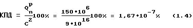
Итак, в соответствии с выражением (1,4) в энергию реактивной тяги переходит не более 10-7% от массы химического топлива. По этой причине современный космический корабль представляет в основном емкость для топлива с небольшим полезным грузом, хотя и в состоянии обеспечить вывод груза на околоземную орбиту. Полеты же с экипажам уже Луне представляют собой довольно серьезную проблему и совмещены с высоким риском. Полеты с экипажем к ближайшим планетам (Марсу и Венере) на кораблях с реактивным двигателем даже не планируются.The disadvantage of this method of creating jet thrust is the low utilization of the energy of chemical fuel in a jet engine, which can be expressed as the full efficiency through the ratio of the useful energy W a when burning fuel to the total energy W o initially accumulated in the fuel mass
![]()
Useful energy W a is determined through the mass m about fuel and its energy output Q n p (calorific value)
W a = Q n p m o (1.2)
The total energy W o accumulated in the fuel is defined as the rest energy through the rest mass m o and the square of the speed of light C 2 in vacuum (C = 3 • 10 8 m / s) in accordance with the principle of equivalence of mass and energy
W o = m o C 2 (1.3)
Substituting (2) and (3) into (1), we obtain the total efficiency of a chemical fuel jet engine, which even for hydrogen fuel Q n p = 150 MJ / kg is a rather small quantity
So, in accordance with expression (1.4), no more than 10 -7 % of the mass of chemical fuel goes into the energy of jet propulsion. For this reason, a modern spaceship is mainly a fuel tank with a small payload, although it is able to provide the launch of the cargo into low Earth orbit. Flights with crews already on the Moon are a rather serious problem and are associated with high risk. Flights with a crew to the nearest planets (Mars and Venus) on ships with a jet engine are not even planned.
Известен способ создания тяги в вакуумном поле путем воздействия на рабочее тело вращающихся неоднородных электрических и магнитных скрещивающихся полей и полевой двигатель, корпус которого одновременно может являться корпусом для космического корабля (см. Леонов B.C. Теория упругой квантованной среды, ч. 2, Новые источники энергии. Минск.: Полибиг, с.93-104, рис. 22, 24). A known method of creating traction in a vacuum field by exposing the working fluid to rotating inhomogeneous electric and magnetic crossing fields and a field engine, the casing of which can simultaneously be a casing for a spacecraft (see Leonov BC Theory of Elastic Quantized Medium,
Недостатками известных способа полевых двигателей являются невозможность создания тяги в связи с отсутствием операций и соответствующих деталей взаимодействия с вакуумным полем системы электрических и магнитных полей. The disadvantages of the known method of field engines are the inability to create traction due to the lack of operations and the corresponding details of the interaction with the vacuum field of the system of electric and magnetic fields.
Техническим решением, на достижение которого направлено изобретение, является создания тяги в вакууме за счет взаимодействия с вакуумным полем системы электрических и магнитных полей, реализация которого позволила бы обеспечить создание эффективного полевого двигателя для межпланетного космического корабля нового поколения с одновременным генерированием электрической энергии. The technical solution to which the invention is directed is to create traction in a vacuum due to the interaction of a system of electric and magnetic fields with a vacuum field, the implementation of which would ensure the creation of an effective field engine for a new generation interplanetary spacecraft with the simultaneous generation of electric energy.
Реализация предлагаемого технического решения позволяет обеспечить создание эффективного полевого двигателя для межпланетного космического корабля нового поколения. The implementation of the proposed technical solution allows for the creation of an effective field engine for a new generation of interplanetary spacecraft.
Указанный технический результат достигается тем, что в способе создания тяги в вакууме путем воздействия на рабочее тело системой вращающихся неоднородных электрических и магнитных скрещивающихся полей задают одновременно электрические и магнитные свойства рабочему телу, вращая которое перераспределяют квантовую плотность среды вакуумного поля внутри рабочего тела в направлении, противоположном вектору силы тяги в результате деформации вакуумного поля, при этом вектор силы тяги расщепляют на нормальный и тангенциальный вектора, нормальный вектор силы направляют на создание силы тяги, а тангенциальный вектор - на создание вращающего момента, обеспечивающего производство электрической энергии для питания системы неоднородных электрических и магнитных скрещивающихся полей и системы их вращения, причем силу тяги задают постоянной величиной на маршруте межпланетного движения и устанавливают из условия эквивалентности создаваемого ускорения, равного ускорению свободного падения на поверхности Земли, периодически меняют направление вектора силы тяги и ускорения на противоположное и обеспечивают движение в режиме разгона и с последующим торможением. The specified technical result is achieved by the fact that in the method of creating traction in vacuum by acting on the working fluid with a system of rotating inhomogeneous electric and magnetic crossing fields, the electrical and magnetic properties of the working fluid are set simultaneously, rotating which redistributes the quantum density of the vacuum field inside the working fluid in the opposite direction vector of traction force as a result of deformation of the vacuum field, while the vector of traction force is split into normal and tangential vectors, n The primary force vector is directed to the creation of the thrust force, and the tangential vector is directed to the creation of a torque providing the production of electric energy to power the system of inhomogeneous electric and magnetic crossing fields and the system of their rotation, and the thrust force is set to a constant value on the interplanetary motion path and set from the condition the equivalence of the created acceleration equal to the acceleration of gravity on the Earth’s surface, periodically change the direction of the vector of thrust and acceleration to the opposite and provide movement in acceleration mode and subsequent braking.
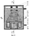
Указанный технический результат достигается также тем, что полевой двигатель для космического корабля, содержащий корпус, аккумуляторную батарею, систему управления тягой, магнитную систему и систему разнополярных электродов, содержит электрогенератор, преобразователь напряжения и активаторы вакуумного поля, включающие электродвигатель, ротор, выполненный в виде рабочего тела из диэлектрического и ферромагнитного материала в форме усеченного конуса, основание которого соосно совмещено с ротором электродвигателя, преимущественно гиромотора, магнитную систему и систему разнополярных электродов, которые охватывают с зазором конус рабочего тела, причем полюса магнитной системы повернуты относительно системы разноименных электродов на угол 90o таким образом, чтобы вектора напряженности магнитного и электрического полей образовали систему скрещивающихся полей, а группа активаторов соединена с осью электрогенератора посредством диска с его торца и снабжена устройством поворота активаторов относительно плоскости диска со средством шарнирного соединения, преобразователь тока аккумуляторной батареи снабжен регулятором частоты трехфазного источника напряжения для питания гиромоторов, а система управления тягой содержит регулятор напряжения магнитной системы и системы разноименных электродов.The specified technical result is also achieved by the fact that the field engine for the spacecraft, comprising a housing, a battery, a traction control system, a magnetic system and a system of bipolar electrodes, contains an electric generator, a voltage converter, and vacuum field activators, including an electric motor, a rotor made in the form of a working bodies of dielectric and ferromagnetic material in the form of a truncated cone, the base of which is coaxially aligned with the rotor of the electric motor, mainly a motor, a magnetic system and a system of bipolar electrodes, which cover the cone of the working fluid with a gap, the poles of the magnetic system rotated relative to the unlike electrode system by an angle of 90 ° so that the magnetic and electric field intensity vectors form a system of crossing fields, and the group of activators is connected to the axis of the generator through the disk from its end and is equipped with a device for turning the activators relative to the plane of the disk with a swivel, transform Vatel battery current is provided with a frequency controller for three-phase voltage source giromotorov power and traction control system includes a voltage regulator of the magnetic system and a system of opposite electrodes.
Указанный технический результат достигается также тем, что полевой двигатель для космического корабля, содержащий корпус, служащий также корпусом космического корабля, аккумуляторную батарею, систему управления тягой, магнитную систему и систему разнополярных электродов, отличается тем, что содержит кольцевые электрогенераторы, преобразователь напряжения и активаторы вакуумного поля, включающие электродвигатель и ротор, выполненный в виде рабочего тела из ферромагнитного диэлектрического материала в форме усеченного конуса, основание которого соосно совмещено с ротором электродвигателя, преимущественно гиромотора, магнитную систему, выполненную в виде многофазной системы магнитных полюсов, и систему разнополярных электродов, выполненную в виде многофазной системы с одинаковым количеством пар магнитных полюсов и пар разнополярных электродов, образующих систему синхронно вращающихся в одном направлении электрических и магнитных полей с пространственным сдвигом на 90o векторов напряженности магнитного и электрического скрещивающихся полей, охватывающую с зазором конус рабочего тела, при этом между магнитными полюсами и системой разнополярных электродов установлен изолятор из диэлектрического материала в форме конуса, кольцевые электрогенераторы установлены в корпусе полевого двигателя по периметру с внутренней стороны на двух уровнях и выполнены с неподвижными статорами и вращающимися в разные стороны роторами, с внутренней стороны роторов установлены активаторы вакуумного поля с наклоном оси к плоскости вращения роторов, причем угол наклона активаторов у одного из роторов противоположен углу наклона активаторов другого ротора, преобразователь напряжения снабжен регулятором частоты трехфазного напряжения для питания гиромоторов, а система управления тягой содержит регулятор напряжения магнитной системы и системы разноименных электродов, при этом активаторы по питанию разбиты на группы для регулирования тяги с любой из сторон космического корабля для осуществления его поворота при маневре.The specified technical result is also achieved in that the field engine for the spacecraft, comprising a housing that also serves as the spacecraft’s hull, a storage battery, a traction control system, a magnetic system and a system of bipolar electrodes, is characterized in that it contains ring electric generators, a voltage converter, and vacuum activators fields including an electric motor and a rotor made in the form of a working fluid from a ferromagnetic dielectric material in the form of a truncated cone, which coaxially coincides with the rotor of an electric motor, mainly a gyromotor, a magnetic system made in the form of a multiphase system of magnetic poles, and a system of different-polar electrodes made in the form of a multiphase system with the same number of pairs of magnetic poles and pairs of different-polar electrodes forming a system of synchronously rotating in one direction electric and magnetic fields with a spatial shift of 90 o vectors of intensity of the magnetic and electric crossing fields, covering the cone of the working fluid, while between the magnetic poles and the system of bipolar electrodes an insulator of dielectric material in the form of a cone is installed, ring electric generators are installed in the field motor housing along the perimeter from the inside on two levels and are made with fixed stators and rotors rotating in different directions, activators of a vacuum field with an inclination of the axis to the plane of rotation of the rotors are installed on the inner side of the rotors, and the angle of inclination of the activators in one of the rotors is opposite the angle of inclination of the activators of the other rotor, the voltage converter is equipped with a three-phase voltage frequency regulator to power the gyromotors, and the traction control system contains a voltage regulator of the magnetic system and the unlike electrodes system, while the power activators are divided into groups to regulate the thrust from either side of the spacecraft for the implementation of its rotation during maneuver.
На фиг. 1 представлена схема, объясняющая появление силы тяготения, действующей на пробную массу 2 и обусловленной градиентом квантовой плотности 3 среды (вакуумного поля) в результате сферической деформации вакуумного поля возмущающей гравитационной массой 1 (чертеж усечен). In FIG. 1 is a diagram explaining the appearance of a gravitational force acting on the
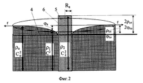
На фиг. 2 представлена гравитационная диаграмма в виде эпюры распределения квантовой плотности среды и гравитационного потенциала во внешней области 4 (ρ1, C2) и внутри 5 (ρ2, C
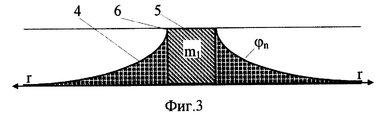
На фиг.3 показано классическое распределение ньютоновского потенциала в вакууме. Figure 3 shows the classical distribution of Newtonian potential in vacuum.
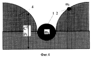
На фиг.4 показана потенциальная гравитационная яма, полученная во внешней области 4 вакуумного поля в результате его возмущения массой 1, наличие которой объясняет природу тяготения массы 2 к массе 1 в результате падения массы 2 на дно потенциальной гравитационной ямы. Figure 4 shows the potential gravitational pit obtained in the
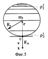
На фиг. 5 показано градиентное распределение квантовой плотности среды внутри тела в результате воздействия на тело массой m2 ускоряющей силы Fm.In FIG. 5 shows the gradient distribution of the quantum density of the medium inside the body as a result of the action of the accelerating force F m on the body of mass m 2 .
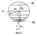
На фиг.6 показано возникновение ускоряющей силы Fm, действующей на тело массой m2 при деформации вакуумного поля внутри тела в направлении силы Fm.Figure 6 shows the occurrence of an accelerating force F m acting on a body of mass m 2 during deformation of the vacuum field inside the body in the direction of the force F m .
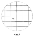
На фиг.7 представлена однородная сетка гравитационного поля внутри тела в отсутствие градиента квантовой плотности среды при равномерном и прямолинейном движении тела в вакуумном поле или его неподвижности. Figure 7 shows a homogeneous grid of the gravitational field inside the body in the absence of a gradient of the quantum density of the medium with uniform and rectilinear motion of the body in a vacuum field or its immobility.
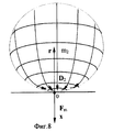
На фиг. 8 представлена неоднородна сетка градиентного вакуумного поля внутри тела в виде силовых линий вектора деформации D2 и эквипотенциалей ньютоновского гравитационного потенциала, приводящих к появлению неуравновешенной ускоряющей силы Fm.In FIG. Figure 8 shows an inhomogeneous grid of a gradient vacuum field inside the body in the form of force lines of the deformation vector D 2 and equipotentials of the Newtonian gravitational potential, leading to the appearance of an unbalanced accelerating force F m .
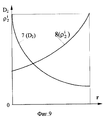
На фиг. 9 представлены градиентные зависимости изменения квантовой плотности ρ
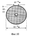
На фиг.10 представлена структура электрического (магнитного) монополя. Figure 10 shows the structure of the electric (magnetic) monopole.
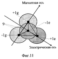
На фиг. 11 показано формирование кванта пространства (квантона) из четырех монопольных зарядов с тетраэдрной моделью расположения ядер монополей (вид сверху). In FIG. 11 shows the formation of a quantum of space (quanton) of four monopole charges with a tetrahedral model of the arrangement of monopole nuclei (top view).
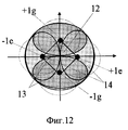
На фиг.12 показано формирование шаровой формы квантона в результате электромагнитного сжатия монополей в квадрупольной конструкции квантона. On Fig shows the formation of the spherical shape of the quanton as a result of electromagnetic compression of monopoles in the quadrupole design of the quanton.
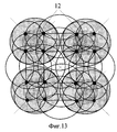
На фиг. 13 представлена упрощенная схема взаимодействия четырех квантонов, представленная в силовых линиях в локальной области вакуумного поля. In FIG. 13 shows a simplified diagram of the interaction of four quantons, presented in the lines of force in the local region of the vacuum field.
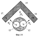
На фиг. 14 представлена схема возникновения градиентной силы Fg, действующей на магнитный диполь 13 квантона 12 в неоднородном магнитном поле.In FIG. 14 is a diagram of the occurrence of a gradient force F g acting on a
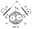
На фиг. 15 представлена схема возникновения градиентной силы Fe, действующей на электрический диполь 14 квантона 12 в неоднородном электрическом поле.In FIG. 15 is a diagram of the occurrence of a gradient force F e acting on an
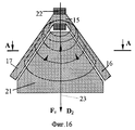
На фиг. 16 представлено воздействие на рабочее тело 21 неоднородного магнитного поля, создаваемого магнитной системой с катушкой возбуждения. In FIG. 16 shows the effect on the working
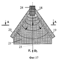
На фиг. 17 представлено воздействие на рабочее тело 21 неоднородного электрического поля создаваемого системой электродов разноименной полярности. In FIG. 17 shows the effect on the working
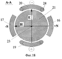
На фиг. 18 показано совмещение воздействия магнитного и электрического полей на рабочее тело 21 при условии ортогональности их векторов напряженности. In FIG. 18 shows the combination of the effects of magnetic and electric fields on the working
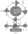
На фиг.19 представлена схема устройства простейшего полевого двигателя. On Fig presents a diagram of a simple field engine.
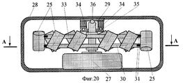
На фиг. 20 представлена схема полевого двигателя с устройством поворота активаторов. In FIG. 20 is a diagram of a field engine with a device for turning activators.
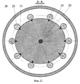
На фиг. 21 представлена схема полевого двигателя с устройством поворота активаторов (в сечении по А-А). In FIG. 21 is a diagram of a field engine with a device for turning activators (in section AA).
На фиг.22 показан активатор вакуумного поля в разрезе по магнитной системе. On Fig shows the activator of the vacuum field in the context of the magnetic system.
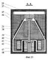
На фиг.23 показан активатор вакуумного поля в разрезе по системе разнополярных электродов (сечение по А-А). On Fig shows the activator of the vacuum field in the context of a system of bipolar electrodes (section AA).
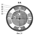
На фиг. 24 представлен активатор вакуумного поля в разрезе по магнитной системе и по системе разнополярных электродов (сечение по В-В). In FIG. 24 shows the activator of the vacuum field in the context of the magnetic system and the system of bipolar electrodes (section along BB).
На фиг.25 представлена схема полевого двигателя межпланетного космического корабля в едином совмещенном корпусе (в сечении). On Fig presents a diagram of the field engine of an interplanetary spacecraft in a single combined body (in cross section).
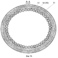
На фиг.26 представлена схема полевого двигателя межпланетного космического корабля в едином совмещенном корпусе (в сечении по А-А). On Fig presents a diagram of the field engine of an interplanetary spacecraft in a single combined body (in section along aa).
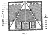
На фиг.27 показан активатор вакуумного поля с многофазной системой магнитных полюсов и разнополярных электродов (в разрезе). On Fig shows the activator of the vacuum field with a multiphase system of magnetic poles and bipolar electrodes (in the context).
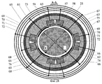
На фиг.28 показан активатор вакуумного поля с многофазной системой магнитных полюсов и разнополярных электродов (в разрезе по А-А). On Fig shows the activator of the vacuum field with a multiphase system of magnetic poles and bipolar electrodes (in the context of aa).
С целью обоснования предлагаемого способа ниже приводятся необходимые расчеты и поясняющие теоретические выкладки. В основе предлагаемого изобретения лежат физические процессы, происходящие в вакуумном поле и раскрывающие механизмы гравитации и инерции. На фиг.1 показано, что в поле тяготения Земли 1 с массой m1 другое тело 2 с массой m2 притягивается в соответствии с законом всемирного тяготения Ньютона с силой Fm, направленной к центру земли по радиусу r (1r - единичный вектор в направлении г, позиция 3 - эквипотенциали квантовой плотности вакуумной среды)
![]()
где =6,67ю10-11Нм2/кг2 - гравитационная постоянная.In order to justify the proposed method, the necessary calculations and explanatory theoretical calculations are given below. The basis of the invention are physical processes that occur in a vacuum field and reveal the mechanisms of gravity and inertia. Figure 1 shows that in the gravitational field of Earth 1 with mass m 1, another
![]()
where w = 6.67 10 -11 Nm 2 / kg 2 - gravitational constant.
Закон всемирного тяготения Ньютона (1) базируется на решении классического уравнения Пуассона для гравитационного потенциала φ, наличие которого в пространстве создается возмущающей массой, например, Земли m1 с плотностью вещества ρm(кг/м3) (см. Новиков И.Д. Тяготение. Физический энциклопедический словарь. М.: Советская энциклопедия, 1984, с.772-775) [3]
Δφ = 4πGρm (2)
где Δ - оператор Лапласа
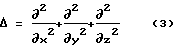
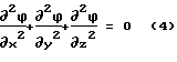
Если плотность вещества ρm сосредоточена в ограниченном объеме, то вне этого объема при условии ρm = 0 уравнение Пуассона (2) переходит в уравнение Лапласа
Решением уравнения Пуассона (2) в области, удовлетворяющей условию Лапласа (4), является функция распределения гравитационного потенциала φ, определяемая интегралом по объему V
![]()
Для сферически симметричной системы распределение гравитационного потенциала (5) описывается ньютоновским гравитационным потенциалом φn
![]()
Значение 1/r в (6) представляет собой кривизну гравитационного поля обусловленного искривлением пространства возмущающей массой m1.Newton's law of universal gravitation (1) is based on the solution of the classical Poisson equation for the gravitational potential φ, the presence of which in space is created by a disturbing mass, for example, the Earth m 1 with a density of matter ρ m (kg / m 3 ) (see Novikov I.D. Gravity, Physical Encyclopedic Dictionary, Moscow: Soviet Encyclopedia, 1984, pp. 772-775) [3]
Δφ = 4πGρ m (2)
where Δ is the Laplace operator
If the density of matter ρ m is concentrated in a limited volume, then outside this volume, provided ρ m = 0, the Poisson equation (2) goes over to the Laplace equation
The solution of the Poisson equation (2) in the region satisfying the Laplace condition (4) is the distribution function of the gravitational potential φ, determined by the integral over the volume V
![]()
For a spherically symmetric system, the distribution of the gravitational potential (5) is described by the Newtonian gravitational potential φ n
![]()
The
Наличие кривизны пространства приводит к появлению обобщающей силы, препятствующей искривлению пространства. Но это не отражено в известных решениях уравнения Пуассона (2). Отсутствие силы, препятствующей искривлению пространства, должно было бы привести к неустойчивости пространства, то есть к его коллапсу. Но этого не наблюдается экспериментально. Пространство как носитель гравитационного поля представляет собой очень устойчивую субстанцию. Это возможно только в том случае, если сила, препятствующая искривлению пространства, существует реально. Но наличие такой силы может быть связано только с наличием упругих свойств у пространства, определяемых его реальной структурой, учет которой позволяет ввести в решения уравнения Пуассона вторую компоненту, препятствующую искривлению пространства. The presence of the curvature of space leads to the appearance of a generalizing force that prevents the curvature of space. But this is not reflected in the well-known solutions of the Poisson equation (2). The absence of a force that impedes the curvature of space would lead to the instability of space, that is, to its collapse. But this is not observed experimentally. Space as a carrier of the gravitational field is a very stable substance. This is only possible if the force that impedes the curvature of space really exists. But the presence of such a force can only be associated with the presence of elastic properties in space, determined by its real structure, taking into account which allows introducing into the solutions of the Poisson equation a second component that prevents the curvature of space.
Кстати, на наличие данной силы указывал академик Дмитрий Сахаров, подвергая серьезной критике существующие теории гравитации, не только ньютоновскую, но и эйнштейновскую (см. Сахаров А.Д. Вакуумные квантовые флуктуации в искривленном пространстве и теория гравитации. Доклады Академии наук СССР, 1967, том 177, 1, с.70-71) [4]. By the way, the presence of this force was pointed out by Academician Dmitry Sakharov, seriously criticizing existing theories of gravity, not only Newtonian, but also Einstein's (see Sakharov A.D. Vacuum quantum fluctuations in curved space and the theory of gravity. Reports of the USSR Academy of Sciences, 1967,
Действительно, уравнение Пуассона (2) вошло в теорию гравитации из теории упругости при решении стационарных задач в механике сплошных сред. В векторной форме уравнение Пуассона (2) представляет собой дивергенцию градиента гравитационного потенциала, определяя свойства пространства как субстанции, обладающей идеальной упругостью (без трения и пластичности)
![]()
Но выражение (7) характеризует собой плотность источника гравитационного поля (интенсивность), хотя в теории гравитации напрямую не учитывает самих упругих свойств гравитационного поля как поля силового.Indeed, the Poisson equation (2) entered the theory of gravity from the theory of elasticity in solving stationary problems in the mechanics of continuous media. In vector form, the Poisson equation (2) is the divergence of the gradient of the gravitational potential, determining the properties of space as a substance with perfect elasticity (without friction and plasticity)
![]()
But expression (7) characterizes the density of the source of the gravitational field (intensity), although in the theory of gravity it does not directly take into account the elastic properties of the gravitational field itself as a force field.
Чтобы перейти от абстрактной величине гравитационного потенциала в (7) к реальному гравитационному полю, наделим вакуум упругой структурой, представив что он состоит из мельчайших частиц - квантов пространства, которые обладают свойством притягиваться друг к другу, образуя упругую квантованную среду (УКС). В теории УКС [5] рассматривается методика электромагнитного квантования пространства с дискретностью порядка 10-25 м на микроуровне в рамках неподвижной лоренцевой абсолютно упругой структуры (Леонов B.C. Роль сверхсильных взаимодействий при синтезе элементарных частиц. В книге "Четыре доклада по теории упругой квантованной среды УКС". Отдельное издание по материалам 6-й конференции РАН "Современные проблемы естествознания". - С. -Петербург, 2000, с.3-14.) [5].In order to move from the abstract value of the gravitational potential in (7) to the real gravitational field, we endow the vacuum with an elastic structure, imagining that it consists of the smallest particles - space quanta, which have the property of being attracted to each other, forming an elastic quantized medium (UKS). In the theory of UKS [5], a method is considered of electromagnetic quantization of space with a discreteness of the order of 10 -25 m at the micro level in the framework of a fixed Lorentz absolutely elastic structure (Leonov BC The role of superstrong interactions in the synthesis of elementary particles. In the book "Four reports on the theory of elastic quantized medium UKS" A separate publication based on the materials of the 6th conference of the Russian Academy of Sciences "Modern problems of natural sciences." - S.-Petersburg, 2000, pp. 3-14.) [5].
Квантованный электромагнитный физический вакуум на макроуровне рассматривается как специфическая сплошная среда, обладающая идеальной (без трения и пластичности) упругостью за счет колоссальных сил внутреннего натяжения собственного статического дискретного электромагнитного поля, исследования которого только начинаются (Дмитриев В.П. Упругая модель физического вакуума. Известия РАН. Механика твердого тела, 1992, 6, с. 66-79. [6]. Смирнов В. И. Экспериментальная проверка гипотезы о существовании статического электромагнитного поля. - Дубна: Объединенный институт ядерных исследований, 1999, препринт Р13-99-7. [7]. The quantized electromagnetic physical vacuum at the macro level is considered as a specific continuous medium with ideal (without friction and plasticity) elasticity due to the colossal forces of internal tension of its own static discrete electromagnetic field, the studies of which are just beginning (Dmitriev V.P. Elastic model of physical vacuum. Izvestiya RAS Solid State Mechanics, 1992, 6, pp. 66-79. [6]. Smirnov VI. Experimental verification of the hypothesis of the existence of a static electromagnetic field. - Dubna: bedinenny Institute for Nuclear Research, 1999, preprint R13-99-7. [7].
Решение стационарных задач деформации в теории упругости и механике сплошных сред определяется классическим уравнением Пуассона (7) и, в данном случае, определяется при замене гравитационного потенциала φ на квантовую плотность упругой сплошной среды ρ, которая характеризует количество частиц (квантов пространства) в единице объема среды (частиц/м3). Получаем новое перенормированное уравнение Пуассона, приведенное к квантовой плотности среды как непосредственного параметра упругих свойств упругого вакуума
ρm = kodiv grad(ρ) (8)
где
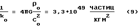

где 1/ko= 3,3•1049 частиц/кгм2 - постоянная невозмущенного деформацией упругого вакуума; Co 2=8,99•1016 м2/c2 -гравитационный потенциал невозмущенного упругого вакуума; ρo = 3,5510•1075 частиц/м3 - квантовая плотность невозмущенного упругого вакуума [5].The solution of stationary deformation problems in the theory of elasticity and continuum mechanics is determined by the classical Poisson equation (7) and, in this case, is determined by replacing the gravitational potential φ with the quantum density упруг of the elastic continuous medium, which characterizes the number of particles (space quanta) per unit volume of the medium (particles / m 3 ). We obtain a new renormalized Poisson equation reduced to the quantum density of the medium as a direct parameter of the elastic properties of the elastic vacuum
ρ m = k o div grad (ρ) (8)
Where
where 1 / k o = 3.3 • 10 49 particles / kgm 2 - constant of unperturbed deformation of the elastic vacuum; C o 2 = 8.99 • 10 16 m 2 / c 2 is the gravitational potential of the unperturbed elastic vacuum; ρ o = 3,5510 • 10 75 particles / m 3 is the quantum density of the unperturbed elastic vacuum [5].
Выражение (8) характеризует состояние деформированного возмущающей гравитационной массой m упругого вакуума, и его решение позволяет найти распределение квантовой плотности вакуумной среды как для внешней области ρ1 деформированного пространства, так и для внутренней ρ2. Для случая сферической деформации вакуума, в результате интегрирования уравнения Пуассона (8), получаем точное решение в виде системы двух уравнений в статике
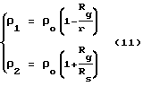
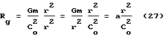
где r - расстояние от центра источника гравитации (r>Rs), м; Rs - радиус источника гравитации (гравитационная граница раздела в среде), м; Rg - гравитационный радиус источника гравитации (без множителя 2), м
![]()
Для элементарных частиц и не коллапсирующих объектов гравитационный радиус является чисто расчетным параметром.Expression (8) characterizes the state of the elastic vacuum deformed by the perturbing gravitational mass m, and its solution allows us to find the distribution of the quantum density of the vacuum medium both for the outer region ρ 1 of the deformed space and for the inner ρ 2 . For the case of spherical vacuum deformation, as a result of integration of the Poisson equation (8), we obtain the exact solution in the form of a system of two equations in statics
where r is the distance from the center of the source of gravity (r> R s ), m; R s is the radius of the source of gravity (gravitational interface in the medium), m; R g - gravitational radius of the source of gravity (without a factor of 2), m
![]()
For elementary particles and non-collapsing objects, the gravitational radius is a purely calculated parameter.
Решение (11) позволяет оценить упругость вакуума, например, по тому как сжимается квантовая плотность среды ρ2 внутри поверхности гравитационной границы раздела Земли, Солнца и черной дыры:
для Земли при Rs=6,37•106м, Rg=4,45•10-3м
ρ2 = 1,0000000007ρo
для Солнца при Rs=6,96•108 м, Rg=1,48•103м
ρ2 = 1,000002ρo
для черной дыры Rg=Rs; ρ2 = 2ρo
Если произойдет коллапс Солнца, то его вещество сожмется в 1,27•1016 раз, в то время как квант пространства сожмется всего в ![]()
for the Earth at R s = 6.37 • 10 6 m, R g = 4.45 • 10 -3 m
ρ 2 = 1.0000000007ρ o
for the Sun at R s = 6.96 • 10 8 m, R g = 1.48 • 10 3 m
ρ 2 = 1.000002ρ o
for a black hole, R g = R s ; ρ 2 = 2ρ o
If the Sun collapses, then its substance will be compressed 1.27 • 10 16 times, while the quantum of space will be compressed only ![]()
Учитывая, что квантовая плотность среды как параметр скалярного поля определяет распределение гравитационного потенциала в вакууме, уточняем решение классического уравнения Пуассона (7) для гравитационного потенциала, определив его распределение для внешней φ1 и внутренней φ2 областей сферически деформированного вакуума
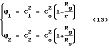
Итак, новые решения (11) и (13) статического уравнения Пуассона для упругого вакуума включают вторую внутреннюю компоненту ρ2 и φ2, которая препятствуют искривлению пространства и уравновешивает внешнюю деформацию (искривление) упругого вакуума, обусловленную параметрами ρ1 и φ1. Такой подход позволяет исключить коллапс пространства, обеспечив его устойчивость.Taking into account that the quantum density of the medium as a parameter of the scalar field determines the distribution of the gravitational potential in vacuum, we refine the solution of the classical Poisson equation (7) for the gravitational potential by determining its distribution for the external φ 1 and internal φ 2 regions of a spherically deformed vacuum
So, new solutions (11) and (13) of the Poisson's static equation for an elastic vacuum include the second internal component ρ 2 and φ 2 , which impede the curvature of space and balances the external deformation (curvature) of the elastic vacuum caused by the parameters ρ 1 and φ 1 . This approach eliminates the collapse of space, ensuring its stability.
Действительно, если выделить в упругом вакууме некую сферическую границу и начать ее равномерно сжимать до радиуса Rs вместе со средой, то внутренняя область сжатия увеличит квантовую плотность среды за счет растяжения внешней области, уравновешивая систему. Этот процесс описывается уравнением Пуассона как дивергенция градиента квантовой плотности среды или гравитационного потенциала. Решения уравнений Пуассона (11) и (13) позволяют составить точный баланс квантовой плотности среды и гравитационных потенциалов для внешней области деформированного вакуума при ρ1 = ρ и φ1 = C
ρo = ρ+ρn (14)
C
где ρn - изменение квантовой плотности среды под действием ньютоновского потенциала φn; φn - ньютоновский гравитационный потенциал (6), м2/с2; С2 - гравитационный потенциал возмущенного гравитацией вакуумного поля, м2/с2.Indeed, if you select a spherical boundary in an elastic vacuum and begin to uniformly compress it to a radius R s together with the medium, then the internal compression region will increase the quantum density of the medium due to stretching of the outer region, balancing the system. This process is described by the Poisson equation as the divergence of the gradient of the quantum density of the medium or gravitational potential. Solutions of the Poisson equations (11) and (13) allow us to make an exact balance of the quantum density of the medium and gravitational potentials for the outer region of the deformed vacuum at ρ 1 = ρ and φ 1 =
ρ o = ρ + ρ n (14)
C
where ρ n is the change in the quantum density of the medium under the action of the Newtonian potential φ n ; φ n - Newtonian gravitational potential (6), m 2 / s 2 ; C 2 - gravitational potential of a vacuum field perturbed by gravity, m 2 / s 2 .
Итак, новые решения уравнения Пуассона вместо одного ньютоновского потенциала φn дают дополнительно еще три гравитационных потенциала Сo 2, φ1 = C2 и φ2, действующих в деформированном вакуумном поле. Это значительно расширяет возможности теории гравитации и упрощает математические расчеты, делая основной упор на реальные физические модели, объясняющие природу гравитации.So, new solutions of the Poisson equation instead of one Newtonian potential φ n give an additional three more gravitational potentials С o 2 , φ 1 = C 2 and φ 2 , acting in a deformed vacuum field. This greatly expands the capabilities of the theory of gravity and simplifies mathematical calculations, focusing on real physical models that explain the nature of gravity.
На фиг. 2 представлена гравитационная диаграмма в виде эпюры распределения квантовой плотности среды и гравитационных потенциалов в соответствии с (13) и (11). Как видно, решение уравнения Пуассона для упругого вакуума определяет его сферическую деформацию. Внутри (позиция 5) гравитационной границы Rs (позиция 6) раздела наблюдается сжатие квантовой плотности среды ρ2 и увеличение гравитационного потенциала φ2 = C
Δρ = 2ρns Δφ = 2φns (16)
где φns - ньютоновский гравитационный потенциал на гравитационной границе раздела Rs, обусловленный квантовой плотностью среды ρns на гравитационной границе, м2/с2.In FIG. Figure 2 shows the gravitational diagram in the form of a diagram of the distribution of the quantum density of the medium and gravitational potentials in accordance with (13) and (11). As can be seen, the solution of the Poisson equation for an elastic vacuum determines its spherical deformation. Inside (position 5) of the gravitational boundary R s (position 6) of the section, there is a compression of the quantum density of the medium ρ 2 and an increase in the gravitational potential φ 2 =
Δρ = 2ρ ns Δφ = 2φ ns (16)
where φ ns is the Newtonian gravitational potential at the gravitational interface R s due to the quantum density of the medium ρ ns at the gravitational boundary, m 2 / s 2 .
Ньютоновский гравитационный потенциал на гравитационной диаграмме (фиг. 2) представлен как потенциал мнимый. Вместо гравитационного потенциала на самом деле в вакуумном поле действует гравитационный потенциал С2. По сути дела замена ньютоновского потенциала на гравитационный потенциал действия С2 представляет собой метод перенормировки гравитационных потенциалов, приводящий к эквивалентности энергий гравитационного и электрического (электромагнитного) полей при неизменном характере гравитационных сил.The Newtonian gravitational potential on the gravitational diagram (Fig. 2) is presented as the imaginary potential. Instead of the gravitational potential, in fact, the gravitational potential C 2 acts in a vacuum field. In fact, replacing the Newtonian potential with the gravitational action potential C 2 is a method of renormalization of gravitational potentials, which leads to the equivalence of the energies of gravitational and electric (electromagnetic) fields with the invariable nature of gravitational forces.
Действительно, из (15) запишем значение гравитационного потенциала действия С2 в вакуумном поле
C2 = C
Внесем в гравитационное поле, определяемое (17), пробную массу m2 и определим силу Fm тяготения между m2 и m1, которая создает потенциал (17), с учетом, что C2 2=const
![]()
Как видно из (18) закон всемирного тяготения с учетом перенормировки гравитационных потенциалов не изменяет своей величины и полученный результат полностью совпадает с известным выражением Ньютона (1). Однако распределение ньютоновского потенциала (фиг.3) в известном законе (1) отлично от распределения гравитационных потенциалов (фиг.2) в теории УКС.Indeed, from (15) we write the value of the gravitational action potential of C 2 in a vacuum field
C 2 = C
We introduce into the gravitational field, defined by (17), the test mass m 2 and determine the gravity force F m between m 2 and m 1 , which creates the potential (17), taking into account that C 2 2 = const
![]()
As can be seen from (18), the law of universal gravitation, taking into account the renormalization of gravitational potentials, does not change its value and the result obtained completely coincides with the well-known Newton's expression (1). However, the distribution of Newtonian potential (figure 3) in the well-known law (1) is different from the distribution of gravitational potentials (figure 2) in the theory of UKS.
Чтобы понять сущность предлагаемого изобретения необходимо уяснить причины тяготения, определяемые выражением (18). С этой целью представим гравитационную диаграмму только в виде гравитационной потенциальной ямы в вакуумном поле, создаваемой возмущающей массой m1 (позиция 1), а внутри гравитационной ямы находится пробная масса m2 (позиция 2) (фиг.4). Как видно, пробная масса 2, находясь внутри гравитационной потенциальной ямы, стремится "упасть" на дно потенциальной ямы под действием сил тяготения. Только на дне потенциальной ямы система принимает устойчивое состояние, связанное с действием гравитации как сил притяжения.To understand the essence of the invention, it is necessary to understand the causes of gravity, defined by the expression (18). To this end, we present the gravity diagram only in the form of a gravitational potential well in a vacuum field created by a disturbing mass m 1 (position 1), and inside the gravitational well there is a test mass m 2 (position 2) (Fig. 4). As you can see, the
Возвращаясь к распределению ньютоновского потенциала на фиг.3, как трактует его механика, нетрудно заметить отсутствие там потенциальной ямы. Returning to the distribution of the Newtonian potential in Fig. 3, as interpreted by its mechanics, it is easy to notice the absence of a potential well there.
Наличие гравитационной потенциальной ямы в вакуумном поле объясняет только внешнюю сторону механизма тяготения, не раскрывая более глубоких его причин. Чтобы проникнуть в суть проблемы перейдем от рассмотрения распределения гравитационного потенциала в вакуумном поле к анализу распределения квантовой плотности среды (11) (фиг. 2). Во внешней области пространства квантовая плотность среды уменьшается по мере приближения к гравитационной границе раздела. Это уменьшение представлено в виде эквипотенциалей 3 квантовой плотности среды на фиг.1. Как видно эквипотенциали сгущаются при удалении от гравитационной границы раздела (в данном случае роль гравитационной границы выполняет поверхность Земли 1). The presence of a gravitational potential well in a vacuum field explains only the external side of the gravitational mechanism, without revealing its deeper causes. To gain insight into the problem, let us move on from considering the distribution of the gravitational potential in a vacuum field to analyzing the distribution of the quantum density of the medium (11) (Fig. 2). In the outer region of space, the quantum density of the medium decreases as it approaches the gravitational interface. This decrease is presented in the form of equipotentials 3 of the quantum density of the medium in figure 1. As can be seen, the equipotentials thicken with distance from the gravitational interface (in this case, the role of the gravitational boundary is played by the Earth's surface 1).
Далее рассмотрим распределение квантовой плотности среды как поля земного тяготения внутри пробной массы 2 (фиг.1). Эквипотенциали квантовой плотности среды гравитационного поля Земли пронизывают тело пробной массы 2, формируя в нем градиент квантовой плотности среды. То есть внутри тела пробной массы 2 квантовая плотность среды распределена неравномерно. И именно эта неравномерность определяет природу тяготения как давление упругой квантованной среды (вакуумного поля) на пробное тело 2. При этом сила Fm тяготения направлена из области с большей квантовой плотностью среды в область меньшей квантовой плотности, то есть на дно гравитационной ямы. Математически это выражается путем замены гравитационного потенциала действия С2 (18) на квантовую плотность среды ρ1 = ρ
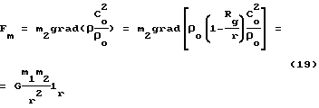
Из (19) видно, что замена гравитационного потенциала квантовой плотностью среду не изменяет самого закона всемирного тяготения. С другой стороны, градиент квантовой плотности среды представляет собой вектор деформации D вакуумного поля
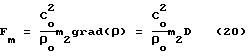
здесь
D = grad(ρ) (21)
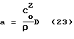
Таким образом, для того чтобы вызвать направленную силу в вакуумном поле необходимо произвести его деформацию в направлении силы. Для этого необязательно производить деформацию вакуумного поля полем тяготения Земли. Если квантовая плотность среды описывает потенциальное гравитационное поле подобно гравитационному потенциалу, то вектор деформации D вакуумного поля является аналогом вектора ускорения а
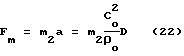
откуда
Если из поля тяготения Земли 1 (фиг. 1) вынести на отдельную фиг.5 пробную массу 2, оставив эквипотенциали 3 квантовой плотности среды вакуумного поля внутри гравитационной границы раздела, а соответственно и деформацию D2 (фиг. 6), то пробная масса будет испытывать воздействие силы Fm несмотря на то, что исходное вакуумное поле не деформировано.Next, we consider the distribution of the quantum density of the medium as a gravitational field inside the test mass 2 (Fig. 1). Equipotentials of the quantum density of the medium of the Earth's gravitational field penetrate the body of the
From (19) it is seen that the replacement of the gravitational potential with quantum density does not change the law of universal gravitation itself. On the other hand, the gradient of the quantum density of the medium is a strain vector D of the vacuum field
here
D = grad (ρ) (21)
Thus, in order to cause a directed force in a vacuum field, it is necessary to deform it in the direction of the force. For this, it is not necessary to deform the vacuum field by the Earth's gravitational field. If the quantum density of the medium describes a potential gravitational field similar to the gravitational potential, then the deformation vector D of the vacuum field is an analog of the acceleration vector a
where from
If, from the Earth's gravitational field 1 (Fig. 1),
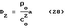
Как видно из фиг.5 тело с пробной массой m2 при воздействии силы Fm в направлении х испытывает ускорение а (23), которое ведет к перераспределению квантовой плотности среды внутри гравитационной границы раздела Rs. Разместим начало координат в точке 0, видно, что внутри тела в направлении r квантовая плотность среды увеличивается от ρ
D2 = grad(ρ2) (24)
Таким образом, чтобы искусственно вызвать силу Fm, действующую на тело и производящую его самопроизвольное ускорение, необходимо внутри тела произвести перераспределение квантовой плотности среды в направлении, противоположном вектору деформации вакуумного поля. Это является первым необходимым действием, обеспечивающим работоспособность предлагаемого способа.As can be seen from Fig. 5, a body with a test mass m 2 under the influence of a force F m in the x direction experiences acceleration a (23), which leads to a redistribution of the quantum density of the medium inside the gravitational interface R s . We place the origin at
D 2 = grad (ρ 2 ) (24)
Thus, in order to artificially cause the force F m acting on the body and spontaneously accelerating it, it is necessary to redistribute the quantum density of the medium inside the body in the opposite direction to the deformation vector of the vacuum field. This is the first necessary action, ensuring the efficiency of the proposed method.
Пока, перераспределение квантовой плотности среды в направлении, противоположном вектору деформации вакуумного поля, наблюдается в поле тяготения, например Земли, и при ускорении тела. Для создания ускорения тела в вакууме пока имеется всего лишь один способ, связанный с реактивным движением, действие которого, в конечном итоге, направлено на перераспределение квантовой плотности среды в направлении, противоположном вектору деформации вакуумного поля. Чтобы полностью отказаться от реактивного движения в космосе, необходимо технически решить проблему перераспределение квантовой плотности среды внутри тела другим способом, отличным от реактивного. So far, the redistribution of the quantum density of the medium in the direction opposite to the deformation vector of the vacuum field is observed in the gravitational field, for example the Earth, and when the body accelerates. So far, there is only one way to create acceleration of a body in vacuum, which is associated with reactive motion, the action of which, ultimately, is aimed at redistributing the quantum density of the medium in the direction opposite to the deformation vector of the vacuum field. In order to completely abandon reactive motion in space, it is necessary to technically solve the problem of redistributing the quantum density of the medium inside the body in a different way than reactive.
В соответствии с принципом эквивалентности тяготения и инерции, сформулированным еще Эйнштейном, применим зависимости, описывающие поле тяготения в виде распределения квантовой плотности ρ1 среды (11) в направлении г для описания распределения квантовой плотности ρ
![]()
Подставляя (25) в (24) получаем функции вектора деформации D2 внутри тела, испытывающего ускорение
![]()
Знак минус в (26) указывает на то, что вектор деформации D2 направлен в противоположную сторону от направления единичного вектора 1r (фиг.6). Гравитационный радиус Rg (12) в (25) и (26) представляет собой своеобразную меру инертности, характеризующую вектор деформации D2, и легко может быть преобразован в напряженность (ускорение а) гравитационного поля, обусловленного инерцией внутри тела
Подставляя (27) в (26) получаем значение вектора деформации D2 вакуумного поля внутри ускоряемого тела в результате искусственного перераспределения квантовой плотности среды
Как видно (28) согласуется с (23). Естественно, что в (27) гравитационный радиус представляет уже собой вектор, как и ускорение а в (28).In accordance with the principle of equivalence of gravity and inertia, formulated by Einstein, we apply the dependences that describe the gravitational field in the form of a distribution of the quantum density ρ 1 of the medium (11) in the direction r to describe the distribution of the quantum
![]()
Substituting (25) into (24) we obtain the functions of the deformation vector D 2 inside the body undergoing acceleration
![]()
The minus sign in (26) indicates that the deformation vector D 2 is directed in the opposite direction from the direction of the unit vector 1 r (Fig.6). The gravitational radius R g (12) in (25) and (26) is a kind of inertia measure characterizing the deformation vector D 2 and can easily be converted to the tension (acceleration a) of the gravitational field due to inertia inside the body
Substituting (27) into (26), we obtain the value of the deformation vector D 2 of the vacuum field inside the accelerated body as a result of the artificial redistribution of the quantum density of the medium
As can be seen (28) is consistent with (23). Naturally, in (27) the gravitational radius is already a vector, as well as the acceleration a in (28).
Таким образом, если внутри тела вызвать искусственно появление вектора деформации D2 вакуумного поля, то это тело станет ускоряться с ускорением а в направлении вектора деформации D2.Thus, if the deformation vector D 2 of the vacuum field is artificially induced inside the body, then this body will accelerate with acceleration a in the direction of the deformation vector D 2 .
На фиг.7 представлена картина вакуумного поля внутри гравитационной границы раздела среды для тела, неподвижного в вакуумном поле и двигающегося в нем равномерно и прямолинейно. Картина вакуумного поля представлена в виде потенциальной сетки, в узлах которой расположены равновеликие гравитационные потенциалы или значения квантовой плотности среды. Как видно, такое гравитационное поле не имеет градиентов квантовой плотности среды, а соответственно не деформировано. В таком поле все силы уравновешены натяжениями гравитационной границы раздела. Figure 7 presents a picture of a vacuum field inside the gravitational interface of a medium for a body motionless in a vacuum field and moving uniformly and rectilinearly in it. The picture of the vacuum field is presented in the form of a potential grid, at the nodes of which are equal gravitational potentials or the values of the quantum density of the medium. As can be seen, such a gravitational field does not have gradients of the quantum density of the medium, and, accordingly, is not deformed. In such a field, all forces are balanced by the tension of the gravitational interface.
На фиг. 8 представлена картина гравитационного поля внутри тела, когда исходное вакуумное поле деформировано и представлено в виде силовых линий вектора деформации D2. Силовые линии сгущаются к точке 0, определяя неоднородность гравитационного поля. Поперечные эквипотенциали отражают характер ньютоновских потенциалов. В результате формируется сетка деформированного поля с явно выраженной неоднородностью, обусловленная градиентами квантовой плотности среды. В итоге, тело с деформированным внутреннем полем создает неуравновешенную силу Fm, способную ускорять тело в пространстве. Внутри тела наблюдается увеличение деформации 7 (D2) вакуумного поля в сторону начала координат 0 за счет ослабления квантовой плотности среды, поскольку деформация проявляется как градиент квантовой плотности 8 среды (фиг.9).In FIG. Figure 8 presents a picture of the gravitational field inside the body when the initial vacuum field is deformed and is represented as the lines of force of the deformation vector D 2 . The lines of force are condensed to
Таким образом, чтобы искусственно создать неуравновешенную силу в вакууме, действующую на тело и производящую тягу, необходимо внутри тела создать условия, приводящие к направленной деформации вакуумного поля в результате градиентного перераспределения квантовой плотности среды. Для этого необходимо раскрыть структуру самого вакуумного пространства, в том числе, внутри гравитационной границы раздела. Thus, in order to artificially create an unbalanced force in a vacuum acting on the body and producing traction, it is necessary to create conditions inside the body that lead to directed deformation of the vacuum field as a result of the gradient redistribution of the quantum density of the medium. For this, it is necessary to reveal the structure of the vacuum space itself, including inside the gravitational interface.
Представленные выше расчеты убедительно доказывают, что вакуумное пространство обладает упругой структурой и должно состоять из большого количества мельчайших частиц - квантов пространства (квантонов), неделимых далее. Чтобы раскрыть структуру элементарного кванта пространства воспользуемся уравнениями Максвелла для вакуума, записав плотность токов электрического je и магнитного jm смещения при поляризации вакуумного поля электромагнитной волной через изменение во времени t напряженности электрического Е и магнитного Н полей [5]
![]()
![]()
где εo = 8,85•10-12Ф/м - электрическая постоянная; μo = 1,26•10-6Гн/м - магнитная постоянная.The above calculations convincingly prove that the vacuum space has an elastic structure and should consist of a large number of tiny particles - space quanta (quantons), indivisible further. To reveal the structure of an elementary quantum of space, we use the Maxwell equations for vacuum, recording the current density of the electric j e and magnetic j m bias when the vacuum field is polarized by an electromagnetic wave through a change in time t of the electric strength E and magnetic H fields [5]
![]()
![]()
where ε o = 8.85 • 10 -12 F / m is the electric constant; μ o = 1.26 • 10 -6 GN / m is the magnetic constant.
Ввиду симметричности электромагнитной волны плотности токов электрического и магнитного смещения в вакууме по абсолютной величине (модулю) эквивалентны друг другу
Jm=CoJe (31)
В (31) плотности токов смещения связаны между собой множителем, равным скорости света Со для невозмущенного гравитацией вакуумного поля, или С - для возмущенного гравитацией. Это обусловлено тем, что размерности плотности токов смещения для электрической и магнитной компонент различны в системе СИ. Действительно, выразить плотности токов смещения можно через скорость смещения v безмассовых элементарных электрического е и магнитного g зарядов и квантовую плотность среды ρo, пологая, что заряды е и g входят в состав квантона парами со знаком (+) и (-), образуя в целом нейтральную частицу
je = 2eρov (32)
jm = 2gρov (33)
Подставляя (32) и (33) в (31) получаем соотношение между элементарным электрическим и магнитным зарядами
g=Coe=4,8•10-11 Ам (или Дк) (34)
Итак, в системе СИ элементарный магнитный заряд (34) имеет величину 4,8•10-11 Ам и размерность, выраженную в Дираках (Дк).Due to the symmetry of the electromagnetic wave, the current densities of electric and magnetic displacement in vacuum in absolute value (modulus) are equivalent to each other
J m = C o J e (31)
In (31), the densities of bias currents are interconnected by a factor equal to the speed of light Co for an unperturbed gravity vacuum field, or C for a perturbed gravity. This is because the dimensions of the density of bias currents for the electric and magnetic components are different in the SI system. Indeed, the displacement current densities can be expressed in terms of the displacement velocity v of massless elementary electric e and magnetic g charges and the quantum density of the medium ρ o , assuming that the charges e and g are part of the quanton in pairs with the signs (+) and (-), forming whole neutral particle
j e = 2eρ o v (32)
j m = 2gρ o v (33)
Substituting (32) and (33) into (31) we obtain the relation between elementary electric and magnetic charges
g = C o e = 4.8 • 10 -11 Am (or Dk) (34)
So, in the SI system, the elementary magnetic charge (34) has a value of 4.8 • 10 -11 Am and a dimension expressed in Dirac (Dk).
Таким образом, анализ уравнений Максвелла показывает, что условием поляризации вакуума электромагнитной волной является наличие токов электрического и магнитного смещения безмассовых электрических и магнитных зарядов, входящих в состав квантона. При этом сам квантон как элементарный квант пространства должен включать в себя четыре элементарных заряда: два электрических (+1е и -1е) и два магнитных (+1g и -1g), представляя собой статический электромагнитный квадруполь, практически не изученный в электродинамике. В дальнейшем будем называть безмассовые элементарные заряды монополями (электрическими и магнитными). Thus, an analysis of Maxwell's equations shows that the condition for vacuum polarization by an electromagnetic wave is the presence of electric and magnetic bias currents of the massless electric and magnetic charges that make up the quanton. In this case, the quanton itself as an elementary quantum of space should include four elementary charges: two electric (+ 1e and -1e) and two magnetic (+ 1g and -1g), representing a static electromagnetic quadrupole, practically not studied in electrodynamics. In what follows, we will call massless elementary charges monopoles (electric and magnetic).
Чтобы выделить в пространстве элементарный объем необходимо с позиций геометрической минимизации всего четыре разметочных точки. Одна точка - просто точка, две точки позволяют выделить линию, три - поверхность, четыре - объем. И эти четыре точки запланировала сама природа в виде указанных четырех монополей, образуя структуру квантона. В целом квантон представляет собой электрически нейтральную и безмассовую частицу, обладающую электрическим и магнитными свойствами, которые проявляются при поляризации вакуума в электромагнитной волне. To select an elementary volume in space, it is necessary from the position of geometric minimization of only four marking points. One point is just a point, two points allow you to select a line, three - a surface, four - volume. And these four points were planned by nature itself in the form of the indicated four monopoles, forming the structure of a quanton. In general, a quanton is an electrically neutral and massless particle with electrical and magnetic properties that manifest themselves when the vacuum is polarized in an electromagnetic wave.
К самой структуре квантона мы не можем подходить с мерками известных элементарных частиц, таких как электрон, обладающий массой и одновременно являющийся носителем элементарного электрического заряда. С классических позиций четыре разноименных монополя в квантоне под действием колоссальных сил натяжения должны коллапсировать в точку. Однако этого не наблюдается. Вакуумное пространство представляет собой очень устойчивую субстанцию. Это означает, что монополи, входящие в квантон, имеют конечные размеры, определяя диаметр Lq самого квантона [5]
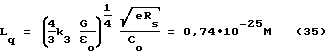
где k3= 1,44 - коэффициент заполнения вакуума квантонами шаровой формы; Rs=0,81•10-15м - радиус протона (нейтрона).We cannot approach the structure of a quanton with the standards of known elementary particles, such as an electron having a mass and simultaneously being a carrier of an elementary electric charge. From classical positions, four opposite monopoles in a quanton under the influence of colossal tension forces should collapse to a point. However, this is not observed. Vacuum space is a very stable substance. This means that the monopoles included in the quanton have finite dimensions, determining the diameter L q of the quanton itself [5]
where k 3 = 1.44 is the filling factor of the vacuum with spherical quantons; R s = 0.81 • 10 -15 m is the radius of the proton (neutron).
Выражение (35) получено из условий натяжения упругого вакуума в результате взаимодействия квантонов между собой при рождении элементарной частицы (протона, нейтрона) из вакуумного поля в результате его сферической деформации. Радиус Rs представляет собой элементарную гравитационную границу раздела в квантованной среде для указанных элементарных частиц.Expression (35) is obtained from the conditions of elastic vacuum tension as a result of the interaction of quantons with each other at the birth of an elementary particle (proton, neutron) from a vacuum field as a result of its spherical deformation. Radius R s represents an elementary gravitational interface in a quantized medium for these elementary particles.
На фиг.10 представлена наиболее вероятная структура электрического и магнитного монополя. По-видимому монополь 9, чтобы удовлетворять условиям упругого состояния вакуумного поля, должен представлять собой двухфазную частицу, состоящую из центрального ядра 10, окруженного упругой атмосферой 11. Именно ядро 10 является источником поля (электрического или магнитного) в виде заряда. Можно предположить, что именно ядро монополя определяется планковской длиной 10-35м, а сам монополь имеет размеры порядка 10-26м [5]. Пока неясна физическая природа самих монопольных зарядов и строение их упругой атмосферы. Упругая атмосфера монополей и сами монополи определяют электрические и магнитные свойства вакуума в виде εo и μo, связывая воедино электрическую и магнитную материю внутри квантона.Figure 10 shows the most likely structure of the electric and magnetic monopole. Apparently, the
Тогда на основании физической модели монопольных зарядов можно анализировать процесс формирования квантона, изображенный на фиг.11. Четыре упругих шарика-монополя 9 образуют фигуру с расстановкой своих ядер по вершинам тетраэдра, обеспечивая ортогональность электрической и магнитной осей в целом нейтрального квантона. Но в таком состоянии квантон оставаться не может. Естественно, что колоссальные силы электромагнитного сжатия должны деформировать квадруполь из монополей в шаровую частицу 12, изображенную на фиг. 12, сохраняя ее целостность как единой частицы и сохраняя ортогональность электрической и магнитной осей. В этом случае ядра монополей шарового квантона также расположены по вершинам тетраэдра, встроенного внутри квантона, обеспечивая электромагнитную симметрию системы. При этом эквивалентное действие электрического и магнитного полей внутри квантона определяется равенством сил Кулона для электрических Fe и магнитных Fg зарядов, действующих на расстоянии г, равном ребру тетраэдра
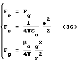
Из (36) получаем соотношение
![]()
Учитывая, что в СИ εoμoC
![]()
Сам процесс электромагнитного квантования большого объема пространства, связан с его заполнением квантонами 12. В силу естественной способности к сцеплению противоположных по знаку зарядов, квантоны сцепляясь друг с другом, образуют квантованную упругую среду. Тетраэдрная форма расстановки ядер монополей в квантонах вносит элемент хаотичности в сцепления квантонов, делая случайным образом ориентацию их электрических и магнитных осей в пространстве и, исключая при этом какое-либо приоритетное направление ориентации. В целом создается электрически и магнитно нейтральная однородная и изотропная среда, обладающая электрическим и магнитными свойствами, получившая название как вакуумное поле в виде статического электромагнитного поля.Then, on the basis of the physical model of monopoly charges, it is possible to analyze the process of formation of the quanton shown in Fig. 11. Four
From (36) we obtain the relation
![]()
Given that in SI ε o μ o C
![]()
The process of electromagnetic quantization of a large volume of space is associated with its filling with
Естественно, что представить структуру дискретного электрического и магнитного поля квантованной среды в проекции на плоскость не представляется возможным. Упрощенная модель плоского локального участка вакуумного поля для четырех квантонов 12 представлена на фиг.13 в проекции на плоскость в виде силовых линий электрического и магнитного полей. Вакуумное поле можно рассматривать в виде дискретной сетки с дискретностью порядка 10-26 м из силовых линий статического электрического и магнитного полей, наброшенной на всю Вселенную и связывающую воедино все объекты. Мы живем в электромагнитной Вселенной.Naturally, it is not possible to imagine the structure of the discrete electric and magnetic fields of a quantized medium in projection onto a plane. A simplified model of a flat local portion of a vacuum field for four
Естественно, что ввиду малых размеров действие электродинамических сил внутри квантона между монопольными зарядами настолько велико, что в природе отсутствуют силы, способные расщепить квантон на отдельные монополи. Экспериментально это подтверждается по отсутствию в природе свободных магнитных зарядов несмотря на многочисленные их поиски. Некоторый избыток электрических зарядов обусловлен электрической асимметрией Вселенной. Но именно избыток электрических зарядов является источником рождения из вакуума элементарных частиц и вещественной материи [5]. Naturally, in view of the small size, the action of electrodynamic forces inside the quanton between monopole charges is so great that in nature there are no forces capable of splitting the quanton into separate monopoles. This is experimentally confirmed by the absence of free magnetic charges in nature, despite their numerous searches. A certain excess of electric charges is due to the electric asymmetry of the Universe. But it is precisely the excess of electric charges that is the source of the production of elementary particles and material matter from vacuum [5].
Итак, анализ электромагнитной структуры вакуумного поля как упругой дискретной субстанции, обусловленной электрическими и магнитными натяжениями между квантонами (квантами пространства), показывает, что воздействуя на вакуумное поле внешними электрическими и магнитными полями, его можно искусственно деформировать в нужном направлении, создавая неуравновешенную силу тяги в соответствии с поставленной в предлагаемом изобретении задачей. С другой стороны, возвращаясь в гравитационной диаграмме фиг.2 становится понятной структура гравитационной диаграммы как области сферически деформированного статического электромагнитного вакуумного поля под действием натяжений гравитационной границы раздела, строение которой для электрона (позитрона) и нуклонов описано в [5]. So, the analysis of the electromagnetic structure of the vacuum field as an elastic discrete substance, caused by electric and magnetic tension between quantons (quanta of space), shows that acting on the vacuum field with external electric and magnetic fields, it can be artificially deformed in the right direction, creating an unbalanced traction force in in accordance with the task of the invention. On the other hand, returning to the gravitational diagram of FIG. 2, the structure of the gravitational diagram as a region of a spherically deformed static electromagnetic vacuum field under the influence of the gravitational interface, the structure of which is described for an electron (positron) and nucleons, is described in [5].
С некоторыми оговорками гравитационную границу Rs раздела как расчетный параметр можно принять при описании гравитационного поля пробного тела с массой m2. Тогда абстрагируясь от того, что пробное тело состоит из атомов и молекул, перейдем к тому, что в конечном итоге, с позиций гравитации, пробное тело можно рассматривать так, что внутри гравитационной границы пробное тело состоит из квантонов, концентрация (квантовая плотность) которых превышает их же концентрацию с внешней стороны в соответствии с (11), испытывая на границе раздела скачок квантовой плотности (16).With some reservations, the gravitational boundary R s of the section as a calculated parameter can be taken in the description of the gravitational field of a test body with mass m 2 . Then, abstracting from the fact that the test body consists of atoms and molecules, let us proceed to the fact that, from the perspective of gravity, the test body can be considered so that inside the gravitational boundary the test body consists of quantons whose concentration (quantum density) exceeds their concentration from the outside in accordance with (11), experiencing a quantum density jump at the interface (16).
Чтобы произвести перераспределение квантовой плотности среды внутри пробного тела необходимо вызвать градиентные силы, способные сместить квантоны внутри гравитационной границы в одном направлении, обеспечив градиент квантовой плотности среды внутри тела. Представленная на фиг.12 схема квантона 12 позволяет рассматривать его как два диполя: магнитного 13 и электрического 14, обладающие дипольными моментами pg и pе соответственно, магнитная и электрические оси которых ортогональны друг другу (фиг.11).To redistribute the quantum density of the medium inside the test body, it is necessary to cause gradient forces that can shift the quantons inside the gravitational boundary in one direction, providing a gradient of the quantum density of the medium inside the body. The scheme of
Если поместить магнитный диполь в неоднородное магнитное поле напряженностью Н, то возникает градиентная магнитная сила Fg, направленная в область наибольшей напряженности магнитного поля, так же как если поместить электрический диполь в неоднородное электрическое поле напряженностью Е, то возникает градиентная электрическая сила Fe, направленная в область наибольшей напряженности электрического поля (см. Тамм И.Е. Основы теории электричества. Издание десятое. М.: Наука, 1989, с.241, 118) [8]
Fg = pggrad(μoH)+pgrot(μoHi) (39)
Fe=pegrad(E)+perot(Ei) (40)
В выражения (39) и (40) входят также напряженности магнитного Нi и электрического Еi полей индуцированные вихревым характером полей при вращении векторов Н и Е.If you place a magnetic dipole in an inhomogeneous magnetic field of intensity H, then a gradient magnetic force F g arises, directed to the region of greatest magnetic field strength, just as if you place an electric dipole in an inhomogeneous electric field of strength E, then a gradient electric force F e directed in the area of greatest electric field strength (see Tamm IE Fundamentals of the theory of electricity. Tenth edition. M: Nauka, 1989, p.241, 118) [8]
F g = p g grad (μ o H) + p g rot (μ o H i ) (39)
F e = p e grad (E) + p e rot (E i ) (40)
Expressions (39) and (40) also include the intensities of the magnetic H i and electric E i fields induced by the vortex nature of the fields during rotation of the vectors H and E.
В целом, выражения (39) и (40) определяют величину и направление градиентных сил Fg и Fe в виде скалярного произведения входящих векторов. Как видно градиенты напряженности электрического и магнитного полей должны совпадать с направлением силы тяги. При отсутствии переменного характера полей в результате их вращения исчезают компоненты с роторами в (39) и (49), определяя чисто статический характер дипольного взаимодействия в градиентном неоднородном поле.In general, expressions (39) and (40) determine the magnitude and direction of the gradient forces F g and F e in the form of a scalar product of incoming vectors. As you can see, the gradients of the electric and magnetic fields must coincide with the direction of the traction force. In the absence of a variable nature of the fields, as a result of their rotation, components with rotors in (39) and (49) disappear, determining the purely static character of the dipole interaction in a gradient inhomogeneous field.
На фиг. 14 представлена схема возникновения градиентной силы Fg, действующей на магнитный диполь 13 квантона 12 в неоднородном магнитном поле магнитной системы 15, полюса которой 16 (+N) и 17 (-S) установлены под углом друг к другу. Магнитный диполь 13 ориентирован вдоль силовой линии неоднородного магнитного поля и испытывает воздействие сил Fg + и Fg - на магнитные заряды внутри квантона 12 со стороны магнитных полюсов 16 (+N) и 17 (-S) системы 15. Градиентная сила Fg является результирующей сил Fg + и Fg -.In FIG. 14 is a diagram of the occurrence of a gradient force F g acting on a
На фиг.15 представлена схема возникновения градиентной силы Fe, действующей на электрический диполь 14 квантона 12 в неоднородном электрическом поле системы электродов 18 разноименной полярности 19 (+) и 20 (-) установленных под углом друг к другу. Электрический диполь 14 ориентирован вдоль силовой линии неоднородного электрического поля и испытывает воздействие сил Fg + и Fg - на электрические заряды внутри квантона 12 со стороны электродов 19 (+) и 20 (-) системы 18. Градиентная сила Fe является результирующей сил Fg + и Fg -.On Fig presents a diagram of the occurrence of the gradient force F e acting on the
Естественно, что на представленных схемах фиг.14 и фиг.15 квантон увеличен до размеров, чтобы можно было разглядеть взаимодействие зарядов квантона с внешними магнитными и электрическими полями. На самом деле размеры квантона очень малы (35) и составляют порядка 10-25м. В реальном теле количество квантонов очень велико, и действие неоднородного поля приводит к смещению квантонов в область наибольшей напряженности поля, осуществляя перераспределение квантовой плотности среды.Naturally, in the presented diagrams of FIG. 14 and FIG. 15, the quanton is enlarged so that it is possible to discern the interaction of the quanton charges with external magnetic and electric fields. In fact, the size of the quanton is very small (35) and amounts to about 10 -25 m. In the real body, the number of quantons is very large, and the action of the inhomogeneous field leads to a shift of the quantons to the region of the highest field strength, redistributing the quantum density of the medium.
Поэтому в предлагаемом способе создания тяги в вакууме помимо необходимости произведения перераспределения квантовой плотности среды внутри рабочего тела в направлении, противоположном вектору деформации вакуумного поля, предусматривается, что само перераспределение квантовой плотности среды осуществляют одновременным воздействием на рабочее тело неоднородных электрических и магнитных скрещивающихся полей. Therefore, in the proposed method for creating thrust in a vacuum, in addition to the need to redistribute the quantum density of the medium inside the working fluid in the direction opposite to the deformation vector of the vacuum field, it is provided that the redistribution of the quantum density of the medium is carried out by simultaneously exposing the working fluid to inhomogeneous electric and magnetic crossing fields.
На фиг.16 рабочее тело 21 находится в неоднородном магнитном поле, создаваемом магнитной системой 15 с катушкой возбуждения 22 и полюсами 16 и 17. Форма рабочего тела 21 соответствует магнитной системе 15 с минимальным воздушным зазором. Силовые линии напряженности градиентного магнитного поля магнитной системы 15 сконцентрированы в области наибольшей напряженности, определяя магнитный поток Ψg, пронизывающий рабочее тело 21 на любом участке, сечением S участка и напряженностью магнитного поля Н
![]()
Концентрация потока в области максимальной напряженности магнитного поля обусловлена неоднородностью магнитного поля, обеспечивая градиентное воздействие на квантоны внутри рабочего тела 21. Градиентные силы, воздействующие на квантоны (обозначены точками), направлены по стрелкам в область наибольшей напряженности магнитного поля и концентрации потока, обеспечивая перераспределение квантовой плотности среды внутри рабочего тела 21. При этом кантоны смещаются в область увеличивающейся концентрации потока, создавая вектор деформации вакуумного поля внутри рабочего тела в направлении, противоположном смещению квантонов (направлению, противоположному концентрации магнитного потока).In Fig.16, the working
![]()
The concentration of the flux in the region of maximum magnetic field strength is due to the inhomogeneity of the magnetic field, providing a gradient effect on the quantons inside the working
На фиг. 17 рабочее тело 21 находится в неоднородном электрическом поле, создаваемом системой электродов 18 разноименной полярности 19 (+) и 20 (-), установленных под углом друг к другу с минимальным воздушным зазором. Форма рабочего тела 21 соответствует системе электродов 18. Крепление электродов 19 и 20 производится с помощью изолятора 24. Силовые линии напряженности градиентного электрического поля системы электродов 18 сконцентрированы в области наибольшей напряженности, определяя электрический поток Ψe, пронизывающий рабочее тело 21 на любом участке, сечением S участка и напряженностью электрического поля Е
![]()
Концентрация потока в области максимальной напряженности электрического поля обусловлена неоднородностью электрического поля, обеспечивая градиентное воздействие на квантоны внутри рабочего тела 21. Градиентные силы, воздействующие на квантоны (обозначены точками), направлены по стрелкам в область наибольшей напряженности электрического поля и концентрации потока, обеспечивая перераспределение квантовой плотности среды внутри рабочего тела 21. При этом кантоны смещаются в область увеличивающейся концентрации потока, создавая вектор деформации вакуумного поля внутри рабочего тела в направлении, противоположном смещению квантонов (направлению, противоположному концентрации магнитного потока).In FIG. 17, the working
![]()
The concentration of the flow in the region of maximum electric field strength is due to the heterogeneity of the electric field, providing a gradient effect on the quantons inside the working
Далее требуется объединение действий градиентных магнитных и электрических полей на рабочее тело. Простое совмещение фиг.16 и фиг.17 не даст ожидаемого результата, поскольку электрические оси квантонов ортогональны друг другу. Поэтому магнитное и электрическое поле в пространстве необходимо разнести так, что бы их вектора напряженности также были бы ортогональны друг другу. Further, a combination of the actions of gradient magnetic and electric fields on the working fluid is required. A simple combination of Fig. 16 and Fig. 17 will not give the expected result, since the electric axes of the quantons are orthogonal to each other. Therefore, the magnetic and electric fields in space must be separated so that their intensity vectors are also orthogonal to each other.
На фиг. 18 показано совмещение воздействия магнитного и электрического полей на рабочее тело 21 при условии ортогональности векторов напряженности E⊥H. Для этого рассмотрим сечение фиг. 16 и фиг.17 и повернем систему электродов 18 в пространстве на 90o. В итоге получаем, что магнитные полюса 16 и 17 создают магнитное поле, главный вектор напряженности Н которого ортогонален главному вектору напряженности Е электрического поля, создаваемого электродами 19 и 20, образуя систему скрещивающихся полей. Поскольку электроды 19 и 20 находятся под высоким электрическим напряжением, то они снабжены градиентными электродами 24, устраняющими концентрацию напряженности электрического поля на электродах с острыми кромками. Под главными векторами напряженности полей понимаются вектора, силовая линия которых направлена между полюсами и электродами по кратчайшему расстоянию. Выделение главного вектора обусловлено тем, что неоднородное поле характеризуется сложной сеткой из силовых линий, и вектора напряженности магнитного и электрического полей точно ортогональны только для главных векторов.In FIG. 18 shows the combination of the effects of magnetic and electric fields on the working
Но для того, чтобы эффективно работал предлагаемый способ создания тяги в вакууме, перечисленных действий с полями оказывается недостаточно. Необходимо обеспечить вращение полей таким образом, чтобы главные вектора напряженности магнитного и электрического полей оставались ортогональными друг другу. Для этого предлагается обеспечить вращение самого рабочего тела 21 относительно оси 23, направленной по вектору деформации D2 вакуумного поля (фиг. 8, 16, 17, 18). При этом возникают дополнительные силы, определяемые роторами магнитного и электрического полей (39) и (40), обеспечивающие усиление воздействия полей и увеличение вектора деформации D2 и силы тяги Fт (фиг.16 и 17).But in order for the proposed method to create traction in a vacuum to work effectively, the listed actions with the fields are not enough. It is necessary to ensure the rotation of the fields so that the main vectors of the magnetic and electric fields remain orthogonal to each other. To this end, it is proposed to ensure the rotation of the working
Поскольку механическая частота вращения рабочего тела ограничена его прочностью, увеличить частоту вращения векторов магнитного и электрического полей, а соответственно и эффективность взаимодействия, предлагается за счет выполнения магнитной системы и системы электродов многофазными (от двух фаз и более), сохраняя ортогональность векторов Н и Е. Многофазные системы позволяют обеспечить вращение векторов электрического и магнитного полей внутри тела независимо от его механического вращения. Since the mechanical frequency of rotation of the working fluid is limited by its strength, it is proposed to increase the rotation frequency of the vectors of magnetic and electric fields, and accordingly the interaction efficiency, by performing a magnetic system and a system of electrodes multiphase (from two phases or more), while preserving the orthogonality of the vectors H and E. Multiphase systems make it possible to ensure the rotation of vectors of electric and magnetic fields inside the body, regardless of its mechanical rotation.
Естественно, что работоспособность предлагаемого способа может быть обеспечена только при наличии у рабочего тела одновременно магнитных и диэлектрических свойств. Naturally, the efficiency of the proposed method can be ensured only if the working fluid has both magnetic and dielectric properties.
В качестве примера, реализующего предлагаемый способ создания тяги в вакууме, на фиг.19 представлена схема устройства полевого двигателя, обеспечивающего не только создание тяги, но и подпитку энергообеспечения за счет колоссальной энергии, изначально аккумулированной в вакуумном поле. Устройство включает активаторы 25 вакуумного поля, кронштейны 26 и электрогенератор 27. As an example, which implements the proposed method of creating traction in vacuum, Fig. 19 shows a diagram of a field engine device that provides not only traction, but also energy supply due to the colossal energy originally accumulated in the vacuum field. The device includes
Нетрудно посчитать, что при размерах квантона (фиг.12) порядка 10-25м энергия связи между монопольными зарядами внутри квантона составляет порядка 10-2Дж. Учитывая концентрацию квантонов порядка 1075частиц/м3, получаем энергоемкость вакуумного поля 1073Дж/м3. Этого достаточно при активизации данной энергии чтобы получить еще один большой взрыв, в результате которого может родиться еще одна вселенная. По сути дела, вакуумное поле является единственным источником энергии во вселенной, различны лишь способы извлечения (активации) этой энергии: химические, ядерные, термоядерные и др.It is easy to calculate that, with the size of the quanton (Fig. 12) of the order of 10 -25 m, the binding energy between the monopole charges inside the quanton is of the order of 10 -2 J. Given the concentration of quantons of the order of 10 75 particles / m 3 , we obtain the energy intensity of the vacuum field 10 73 J / m 3 . This is enough when this energy is activated to get another big explosion, as a result of which another universe can be born. In fact, the vacuum field is the only source of energy in the universe, only the methods of extraction (activation) of this energy are different: chemical, nuclear, thermonuclear, etc.
В данном случае рассматривается способ создания тяги в вакуумном поле с одновременным извлечением из него электрической энергии в результате того, что вектор силы тяги, создаваемой рабочим телом, расщепляют на нормальный и тангенциальный вектора, который в свою очередь направляют на создание вращающегося момента, обеспечивающего производство электрической энергии для питания системы. In this case, we consider a method of creating traction in a vacuum field with the simultaneous extraction of electric energy from it as a result of the fact that the vector of the traction force created by the working fluid is split into a normal and tangential vector, which, in turn, is directed to create a torque that produces electric energy to power the system.
Назовем систему магнитных и электрических полей с рабочим телам единым термином - активатор вакуумного поля, или сокращенно активатор 25. В устройстве на фиг.19 активаторы 25 расположены на кронштейнах 26, которые установлены на валу электрогенератора 27. На фиг.19 не показан электропривод рабочего тела активатора 25, который осуществляется с помощью встроенного гиромотора. We call the system of magnetic and electric fields with working fluids a single term — a vacuum field activator, or
Активаторы 25 установлены осью в направлении создания силы тяги Fт под углом к плоскости вращения кронштейнов 26, расщепляя силу тяги Fт на нормальную Fy и тангенциальную Fx составляющие (вид А). По действием тангенциальной составляющей Fx создается вращающий момент, который, воздействуя на кронштейны 26, установленные на валу электрогенератора 27, приводят во вращение ротор электрогенератора 27. Вырабатываемая энергия идет на подпитывание активаторов 25, создавая магнитные и электрические поля и вращение рабочего тела активатора.The
Экспериментальная проверка предлагаемого способа полностью подтвердила его работоспособность на примере работы полевого двигателя фиг.19. Для пуска полевого двигателя требуется дополнительный источник электрической энергии (электрическая сеть, аккумуляторная батарея). An experimental verification of the proposed method fully confirmed its performance by the example of the field engine of Fig. 19. To start the field engine requires an additional source of electrical energy (mains, battery).
Работает полевой двигатель следующим образом. От источника электрической энергии питается электрогенератор 27 в режиме двигателя и активатор 25. При раскрутке системы до определенной критической скорости в данном случае до 1500 об/мин полевой двигатель входит в двигательный режим. При этом электрогенератор 27 обеспечивает подпитывание активаторов 25 энергией. Тяга, развиваемая полевым двигателем, превосходит вес системы в целом и зависит от конструктивных параметров полевого двигателя, что делает возможным использование предлагаемого полевого двигателя в космических межпланетных кораблях нового поколения. The field engine operates as follows. An
Ниже представлены расчеты полевого двигателя по тяге, мощности и энергии. Below are the calculations of the field engine for traction, power and energy.
1. Запишем основное балансное уравнение для полевого двигателя при движении космического корабля в вакууме
где m1 - масса космического корабля, кг; m2 - масса рабочего тела активатора, кг; n2 - количество активаторов вакуумного поля в полевом двигателе, штук; d2 - деформация вакуумного поля активатором, частиц/м4; a1 - ускорение космического корабля, м/с2.1. We write the basic balance equation for the field engine when the spacecraft moves in vacuum
where m 1 is the mass of the spacecraft, kg; m 2 is the mass of the working fluid of the activator, kg; n 2 - the number of activators of the vacuum field in the field engine, pieces; d 2 - deformation of the vacuum field by the activator, particles / m 4 ; a 1 - spacecraft acceleration, m / s 2 .
2. С учетом (28) выразим деформацию D2 вакуумного поля в (43) через эквивалентную величину ускорения а2, действующего на рабочее тело активатора в результате деформации вакуумного поля
m1a1=n2m2a2 (44)
3. Далее из (44) рассчитаем параметры рабочего тела активатора для полевого двигателя межпланетного космического корабля массой m1=100т=105кг, двигающегося с ускорением, равным ускорению свободного падения на поверхности Земли a1= gi=9,8м/с2, при условии, что ускорение, действующее на рабочее тело активатора, достигает значений a2=1000 gi
m1gi=n2m2•1000gi (45)
откуда
![]()
Далее задаем массу рабочего тела активатора m2=10 кг и из (46) находим требуемое количество активаторов вакуумного поля для полевого двигателя
![]()
4. Определяем силу F2 давления (тяги) на ось рабочего тела активатора
F2=m2a2=m21000gi=10•9,8≈105H (48)
5. Определяем суммарную силу Fт тяги полевого двигателя космического корабля
Fт=n2F2=106H (49)
6. Определяем требуемую энергию W для движении космического корабля с работающим полевым двигателем на пути х для равноускоренного движения
![]()
Энергия, требуемая на прохождение 1 км пути при равноускоренном движении космического корабля
W=Fтx=106•103=109 Дж (51)
С другой стороны, энергия, требуемая на разгон космического корабля до скорости v, определяется его кинетической энергией
![]()
Как видно из (52) кинетическая энергия космического корабля определяется квадратичной зависимостью от его скорости движения в вакуумном поле и зависит от начальной скорости движения vo
Но в (53)v-vo = Δv представляет собой разность скоростей, с учетом которой из (53) получаем
![]()
Как видно из (54) кинетическая энергия зависит от начальной абсолютной скорости vo движения космического корабля относительно вакуумного поля. При vo=0 выражение (54) переходит в (52).2. Taking into account (28), we express the deformation D 2 of the vacuum field in (43) in terms of the equivalent acceleration a 2 acting on the activator’s working medium as a result of deformation of the vacuum field
m 1 a 1 = n 2 m 2 a 2 (44)
3. Next, from (44) we calculate the parameters of the activator working fluid for the field engine of an interplanetary spacecraft of mass m 1 = 100t = 10 5 kg moving with an acceleration equal to the acceleration of gravity on the Earth's surface a 1 = g i = 9.8 m / s 2 , provided that the acceleration acting on the working medium of the activator reaches a 2 = 1000 g i
m 1 g i = n 2 m 2 • 1000g i (45)
where from
![]()
Next, we set the mass of the activator working fluid m 2 = 10 kg and from (46) we find the required number of vacuum field activators for the field engine
![]()
4. Determine the force F 2 pressure (traction) on the axis of the working fluid of the activator
F 2 = m 2 a 2 = m 2 1000g i = 10 • 9.8≈10 5 H (48)
5. Determine the total thrust force F t the field engine of the spacecraft
F t = n 2 F 2 = 10 6 H (49)
6. Determine the required energy W for the movement of the spacecraft with a working field engine on the path x for uniformly accelerated motion
![]()
The energy required to cover 1 km of path with uniformly accelerated spacecraft motion
W = F t x = 10 6 • 10 3 = 10 9 J (51)
On the other hand, the energy required to accelerate a spacecraft to a speed v is determined by its kinetic energy
![]()
As can be seen from (52), the kinetic energy of the spacecraft is determined by the quadratic dependence on its speed in a vacuum field and depends on the initial speed v o
But in (53) vv o = Δv is the velocity difference, taking into account which, from (53) we obtain
![]()
As can be seen from (54), the kinetic energy depends on the initial absolute velocity v o of the spacecraft motion relative to the vacuum field. When v o = 0, expression (54) goes over into (52).
7. Определяем мощность Р полевого двигателя
![]()
Как видно из (55) при постоянной тяге полевого двигателя его мощность возрастает с увеличением скорости в вакуумном поле и при скорости 30 км/с составит
P=Fтv=106•3•104=30 ГВт (56)
Выражение (56) также отражает особенности взаимодействия уже всего вещества космического корабля с энергоемким вакуумным полем, а не только работающего полевого двигателя.7. Determine the power P of the field engine
![]()
As can be seen from (55) with a constant thrust of the field engine, its power increases with increasing speed in a vacuum field and at a speed of 30 km / s will be
P = F t v = 10 6 • 3 • 10 4 = 30 GW (56)
Expression (56) also reflects the features of the interaction of all the spacecraft’s substance with an energy-intensive vacuum field, and not just a working field engine.
8. Время полета до Марса космического корабля с полевым двигателем при условии его непрерывного разгона на половине пути и торможения на второй половине пути, составит:
где х=56•109 м - наиближайшее расстояние от Земли до Марса.8. The flight time to Mars of a spacecraft with a field engine, subject to its continuous acceleration in half the path and braking in the second half of the path, will be:
where x = 56 • 10 9 m is the closest distance from Earth to Mars.
9. Максимальная скорость корабля на пути к Марсу составит:
Как видно, максимальная скорость космического корабля с полевым двигателем при путешествии к Марсу составит 740 км/с, что намного меньше скорости света в вакууме (С=300000 км/с).9. The maximum speed of the ship on the way to Mars will be:
As you can see, the maximum speed of a spacecraft with a field engine when traveling to Mars will be 740 km / s, which is much less than the speed of light in vacuum (C = 300,000 km / s).
Таким образом, проведенные расчеты показывают, что реализация предлагаемого изобретения позволит осуществить разработку нового поколения космических кораблей с полевыми двигателями, способными совершать межпланетные перелеты за несоизмеримо малое время по сравнению с реактивными аппаратами, когда сама сила тяги задается постоянной величиной на маршруте межпланетного движения и устанавливается из условия эквивалентности создаваемого ускорения равного ускорению свободного падения на поверхности Земли, периодически меняя направление вектора силы тяги и ускорения на противоположное и обеспечивая движение в режиме разгона и с последующим торможением. Thus, the calculations show that the implementation of the present invention will allow the development of a new generation of spacecraft with field engines, capable of interplanetary flights in an incomparably short time compared to jet vehicles, when the thrust itself is set at a constant value on the interplanetary route and is set from equivalence conditions for the created acceleration equal to the acceleration of gravity on the Earth’s surface, periodically changing direction the opposite of the traction force and acceleration vector and providing movement in acceleration mode and subsequent braking.
Ниже рассматриваются конкретные варианты конструкции полевых двигателей, реализующих предлагаемый способ создания тяги в вакууме. The following are specific design options for field engines that implement the proposed method of creating traction in a vacuum.
По первому варианту полевой двигатель для космического корабля предназначен для создания тяги в вакууме с помощью системы неоднородных вращающихся электрических и магнитных полей. Полевой двигатель (фиг.20, 21) включает: корпус 28, электрогенератор 27 на валу 29 которого установлен диск 30, активаторы 25, закрепленные на шарнирах 31 с торца диска 30, систему поворота 32 активаторов 25, схему управления, аккумуляторную батарею и преобразователь напряжения (не показаны). Система поворота 32 активаторов 25 состоит из второго диска 33, гидропривода 34 и упорного подшипника 35. Система поворота 32 может быть выполнена любой другой из известных в механике. Конец вала 29 закреплен в корпусе 28 упорным подшипником 36 (или радиально-упорным). In the first embodiment, the field engine for the spacecraft is designed to create thrust in a vacuum using a system of inhomogeneous rotating electric and magnetic fields. The field engine (FIGS. 20, 21) includes: a
Активатор 25 (фиг.22, 23, 24) вакуумного поля (в дальнейшем активатор) включает: корпус 37 с шарнирами 31, рабочее тело 21 с валом 38 и подшипниками 39, электродвигатель 40 состоящий из ротора 41 и статора 42, магнитную систему 43 с катушками 44, систему электродов 45. Рабочее тело 21 выполнено из ферромагнитного диэлектрического материала в виде тела вращения в форме усеченного конуса, основание которого соосно совмещено с ротором 41 электродвигателя 40. Со стороны конуса рабочего тела 21 с зазором установлена магнитная система 43 и система электродов 45, охватывающие конус рабочего тела. Система электродов 45 установлена в корпусе 37 на изоляторах 46 с низкой относительной диэлектрической проницаемостью (фторопласт и др.). В качестве электродвигателя 40 использован гиромотор с внешним шихтованным ротором 41 и короткозамкнутой обмоткой 47, неподвижным шихтованным статором 42 и трехфазной обмоткой 49, питаемой от преобразователя напряжения повышенной частоты. В качестве электродвигателя 40 может быть использован любой подходящий тип электродвигателя. The activator 25 (Fig.22, 23, 24) of the vacuum field (hereinafter the activator) includes: a
Работает полевой двигатель следующим образом. The field engine operates as follows.
От аккумуляторной батареи питается электрогенератор 27 в режиме двигателя и преобразователь напряжения, который выдает три типа напряжений: для питания катушек 44 магнитной системы 43, высокого напряжения для питания системы электродов 45, и переменного напряжения повышенной частоты для питания электродвигателя 40. An
Магнитная система 43 и система электродов 44 создают систему неоднородных полей: магнитное и электрическое с ортогональным расположением главных векторов напряженности в соответствии с предлагаемым способом. Система неоднородных полей воздействует на рабочее тело 21, обеспечивая его магнитную и электрическую поляризацию. Воздействие вращающихся магнитного и электрического полей обеспечивается за счет вращения рабочего тела 21. В результате внутри рабочего тела происходит перераспределение квантовой плотности среды вакуумного поля и создается неуравновешенная сила тяги, передающаяся активатору 25. The
От активатора 25 сила тяги передается дискам 30 и 33, установленным на валу 29 электрогенератора 27. Поскольку активатор 25 установлен под углом осью действия силы тяги к плоскости дисков 30 и 33, происходит расщепление силы тяги на тангенциальную и нормальную. Тангенциальная сила создает вращающий момент, действующий на диски 30 и 33. Суммирование вращающих моментов от действия сил всей группы активаторов 25, установленных радиально с торцов дисков 30 и 33, приводит во вращение диски 30 и 33, и соответственно вал 29 электрогенератора 27. Далее система приходит в двигательный режим, взаимодействуя с вакуумным полем, и таким образом, извлекая из вакуумного поля энергию, которая идет на поддержания вращения электрогенератора 27 для обеспечения питания электрической системы полевого двигателя и на создание полевой тяги. From the
Соотношение энергий, необходимых для вращения электрогенератора 27 и создания полевой тяги, регулируется изменением угла наклона активаторов 25 к плоскости диска 30 за счет изменения расстояния между дисками 30 и 33 с помощью гидропривода 34. The ratio of the energies required to rotate the
Данный тип двигателя может быть применен не только на небольших космических кораблях в качестве маршрутного двигателя, но может быть применен для любого транспортного средства в зависимости от мощности двигателя (автомобиль, трактор, морские суда и др.). This type of engine can be used not only on small spaceships as a block engine, but can be applied to any vehicle depending on engine power (car, tractor, sea vessels, etc.).
По второму варианту полевой двигатель для космического корабля также предназначен для создания тяги в вакууме с помощью системы неоднородных вращающихся электрических и магнитных полей. Существенное отличие полевого двигателя по второму варианту от двигателя по первому варианту заключается в том, что по второму варианту вращение электрических и магнитных полей в активаторе производится за счет многофазных систем питания. Это позволяет увеличить частоту вращения полей и, тем самым, увеличить энергетические показатели двигателя. Кроме того, отлична компоновка данного полевого двигателя и его энергетическое обеспечение. Данный тип двигателя предназначен для установки на крупных межпланетных кораблях. In the second embodiment, the field engine for the spacecraft is also designed to create thrust in a vacuum using a system of inhomogeneous rotating electric and magnetic fields. A significant difference between the field engine in the second embodiment and the engine in the first embodiment is that in the second embodiment, the rotation of the electric and magnetic fields in the activator is due to multiphase power systems. This allows you to increase the frequency of rotation of the fields and, thereby, increase the energy performance of the engine. In addition, the layout of this field engine and its energy supply are excellent. This type of engine is designed for installation on large interplanetary spacecraft.
Полевой двигатель (фиг.25, 26) включает: корпус 49, кольцевой электрогенератор 50, активаторы 51, схему управления, аккумуляторную батарею и преобразователь напряжения (не показаны). Корпус 49 полевого двигателя одновременно является корпусом космического корабля, для усиления жесткости которого служат стойки 52. The field engine (FIGS. 25, 26) includes: a
Кольцевой электрогенератор 50 конструктивно также усиливает жесткость корпуса 49 и выполнен в виде кольца, установленного по периметру корпуса 49, а внутри кольца образуется свободное пространство для размещения оборудования и экипажа. Кольцевой электрогенератор 50 состоит из неподвижного статора 53 и подвижного ротора 54. Кольцевой электрогенератор 50 ввиду большого радиуса выполнен по схеме линейной электромашины со сверхпроводящими обмотками и в данном изобретении не рассматривается конструкция самого электрогенератора. В корпусе 49 установлены два кольцевых электрогенератора 50 и 55 идентичных друг другу, роторы которых 54 и 56 (не виден) вращаются в различные стороны. Это позволяет устранить действие вращающего момента на корпус 49 корабля и полностью компенсировать действие гироскопического момента, мешающего управлению кораблем при его маневре. The ring
Активаторы 51 установлены с внутренней стороны роторов 54 и 56. Активаторы снабжены системой их поворота (не показана) для создания тангенциальной тяги, обеспечивающей вращение роторов электрогенераторов в противоположных направлениях. The
Активатор 51 (фиг.27, 28) вакуумного поля (в дальнейшем активатор) включает: корпус 57, рабочее тело 21 с валом 38 и подшипниками 39, электродвигатель 40 состоящий из ротора 41 и статора 42, магнитную систему 58 с катушками 59, систему электродов 60. Магнитная система 58 и система электродов 60 разделены изолятором 61. The activator 51 (Fig. 27, 28) of the vacuum field (hereinafter the activator) includes: a
Рабочее тело 21 выполнено из ферромагнитного диэлектрического материала в виде тела вращения в форме усеченного конуса, основание которого соосно совмещено с ротором 41 электродвигателя 40. Со стороны конуса рабочего тела 21 с зазором установлена магнитная система 58 и система электродов 60, охватывающие конус рабочего тела. В качестве электродвигателя 40 использован гиромотор с внешним шихтованным ротором 41 с короткозамкнутой обмоткой 47, неподвижным шихтованным статором 42 и трехфазной обмоткой 49, питаемой от преобразователя напряжения повышенной частоты. В качестве электродвигателя 40 может быть использован любой подходящий тип электродвигателя. The working
Магнитная система 58 выполнена многофазной, и в данном случае рассматривается ее двухфазный вариант, включающий две пары полюсов 61, 62 и 63, 64, установленных со смещением в пространстве на 90o относительно друг друга. Магнитное поле полюса 61 возбуждается обмоткой 65, охватывающей данный полюс, полюса 62 - обмоткой 66, полюса 63 - обмоткой 67, полюса 64 - обмоткой 68. Обмотки 65 и 66 первой пары полюсов 61 и 62 соединены электрически параллельно и подключены к первой фазе источника переменного двухфазного тока через шины 69 и 70. Обмотки 67 и 68 второй пары полюсов 63 и 64 соединены электрически параллельно и подключены ко второй фазе источника переменного двухфазного тока через шины 71 и 72. Фазовый сдвиг между фазами напряжений двухфазного источника питания составляет 90o. Данная магнитная система обеспечивает вращение вектора напряженности магнитного поля Н, пронизывающего рабочее тело 21.The
Система электродов 60 также содержит две пары разнополярных электродов 73, 74 и 75, 76 установленных со смещением в пространстве на 90o относительно друг друга. Первая пара электродов 73, 74 установлена на магнитных полюсах 61-62 через изолятор 60. Если обмотки 65 и 66 пары магнитных полюсов 61, 62 подсоединены к первой фазе (шины 69, 70) источника питания, то электроды 73, 74 подсоединены ко второй фазе (шины 71, 72) источника питания. Это обеспечивает сдвиг по фазе напряжения питания электродов 73, 74 на 90o относительно напряжения питания обмоток 65, 66 пары полюсов 61, 62. Вторая пара электродов 75, 76 установлена на магнитных полюсах 63, 64 через изолятор 60. Если обмотки 67 и 68 пары магнитных полюсов 63, 64 подсоединены ко второй фазе (шины 71, 72) источника питания, то электроды 75, 76 подсоединены к первой фазе (шины 69, 70) источника питания. Это обеспечивает сдвиг по фазе напряжения питания электродов 75, 76 на 90o относительно напряжения питания обмоток 67, 68 пары полюсов 63, 64. В целом данная система питания обеспечивает создание вращающихся электрических и магнитных полей, вектора напряженности которых сдвинуты относительно друг друга на 90o (фиг.28) в соответствии с предлагаемым способом.The
Кроме того, магнитная система 58 снабжена обмотками возбуждения, установленными ступенчато по высоте магнитной системы. Это позволяет увеличить напряженность магнитного поля на вершине конуса рабочего тела 21 по сравнению с основанием, и тем самым увеличить градиент напряженности магнитного поля, увеличивая силу тяги полевого двигателя (фиг.27). При работе на низких частотах до 20 кГц магнитная система 58 может быть выполнена наборной из листовой электротехнической стали. На более высоких частотах магнитная система 58 выполняется из ферромагнетика. Ступенчатое увеличение напряженности магнитного и электрического полей по высоте позволяет использовать не только рабочее тело в форме конуса, но и в форме цилиндра, или другой конфигурации. In addition, the
Система электродов 59 отделена от магнитной системы 58 изолятором 60, выполненным в виде сплошного конуса, установленного между электродами и полюсами магнитной системы. При этом система электродов 59 встраивается в изолятор 60, обеспечивая крепление электродов. В данном случае при питании системы электродов переменным напряжением электроды полностью могут быть встроены в изолятор 60, обеспечивая высокие показатели электрической прочности в условиях воздействия сильных электрических полей. Для увеличения напряжения питания системы электродов возможно применение повышающих трансформаторов, устанавливаемых между питающими шинами и электродами. Увеличение напряжения на электродах ведет к увеличению напряженности электрического поля возбуждающего активатор, и ограничено электрической прочностью изолятора со встроенными в него электродами. The
Работает полевой двигатель следующим образом. The field engine operates as follows.
В системе энергообеспечения предлагаемого полевого двигателя в качестве стартового источника питания предлагается использовать небольшой полевой двигатель, рассмотренный по первому варианту данного изобретения (фиг.20). Запуск стартового полевого двигателя производится от небольшой аккумуляторной батареи, а далее пуск основного полевого двигателя (фиг.26) производится уже от стартового полевого двигателя как первичного источника электрического питания для преобразователя напряжения, который выдает три типа напряжений: двухфазного напряжения переменного тока со сдвигом между фазами 90o для питания обмоток 65, 66 и 67, 68 магнитной системы 58, высокого напряжения для питания системы электродов 59 (электроды 73, 74 и 75, 76) и переменного напряжения повышенной частоты для питания электродвигателя 40 привода рабочего тела 21 активатора 51.In the power supply system of the proposed field engine as a starting power source, it is proposed to use a small field engine, considered according to the first embodiment of the present invention (Fig.20). The starting field engine is started from a small battery, and then the main field engine is started (Fig. 26) already from the starting field engine as the primary source of electrical power for the voltage converter, which produces three types of voltage: two-phase AC voltage with a phase shift 90 o for powering the
Магнитная система 58 и система электродов 59 создают систему вращающихся неоднородных полей. При этом магнитное и электрическое поля вращаются с ортогональным расположением главных векторов напряженности в соответствии с предлагаемым способом. Система вращающихся неоднородных полей воздействует на рабочее тело 21, обеспечивая его магнитную и электрическую поляризацию. Дополнительное воздействие вращающихся магнитного и электрического полей обеспечивается за счет вращения рабочего тела 21 с приводом от электродвигателя 40. В результате внутри рабочего тела происходит перераспределение квантовой плотности среды вакуумного поля и создается неуравновешенная сила тяги, передающаяся активатору 51. The
От активатора 51 сила тяги передается ротору 54 кольцевого электрогенератора 50 (статор 53 неподвижен). Поскольку активатор 51 установлен под углом осью действия силы тяги к плоскости ротора 54, происходит расщепление силы тяги на тангенциальную и нормальную. Тангенциальная сила создает вращающий момент, действующий на ротор 54. Суммирование вращающих моментов от действия сил всей группы активаторов 51, установленных на роторе 54, приводит во вращение ротор 54 кольцевого электрогенератора 50. Далее система входит в двигательный режим, взаимодействуя с вакуумным полем и, таким образом, извлекая из вакуумного поля энергию, которая идет на поддержания вращения ротора 54 электрогенератора 50 для обеспечения питания электрической системы полевого двигателя и на создание полевой тяги. Аналогичным образом происходит пуск второго кольцевого электрогенератора 55, ротор 56 которого вращается в направлении, противоположном вращению ротора 54, компенсируя таким образом действие вращающего момента корпуса 49 и компенсируя действие гироскопического момента при маневре корабля. From the
Маневр корабля, связанный с изменением направления его движения, обеспечивается усилением или ослаблением силы тяги активаторов с одной стороны, образуя поворотный момент. Для этого активаторы соединены в группы. Необходимо отметить, что движение межпланетного корабля рассчитано с постоянным ускорением, соответствующим ускорению свободного падения на поверхности Земли. В этом случае экипаж космического корабля не будет испытывать воздействия невесомости при полете, находясь в поле, эквивалентном полю тяготения на поверхности Земли. При движении положение корабля в пространстве определяется направлением вектора скорости движения, нормальным к плоскости сечения А-А (фиг.25). Движение с постоянным ускорением существенно сокращает время полета. The maneuver of the ship, associated with a change in the direction of its movement, is provided by strengthening or weakening the traction force of the activators on the one hand, forming a turning moment. To do this, the activators are connected in groups. It should be noted that the movement of the interplanetary spacecraft is calculated with constant acceleration corresponding to the acceleration of gravity on the Earth's surface. In this case, the crew of the spacecraft will not experience the effects of weightlessness during flight, being in a field equivalent to the gravitational field on the surface of the Earth. When moving, the position of the ship in space is determined by the direction of the velocity vector, normal to the section plane AA (Fig. 25). Constant acceleration significantly reduces flight time.
При экспедиции половину пути корабль проходит с постоянным ускорением, а вторую половину пути проходит с торможением, при этом ускорение и торможение соответствует земному (9,8 м/с2). Время экспедиции до Марса на космическом корабле с полевым двигателем в режиме постоянного ускорения и последующего торможения составит всего 42 часа, то есть около двух земных суток (57). Причем энергия, задействованная из вакуумного поля на ускорение корабля, возвращается вакуумному полю при торможении корабля, обеспечивая законы сохранения энергии и ее кругооборот в вакуумном поле.During the expedition, the ship travels halfway with constant acceleration, and the second half of the journey with braking, while acceleration and braking correspond to the earth (9.8 m / s 2 ). The expedition time to Mars in a spacecraft with a field engine in constant acceleration and subsequent braking mode will be only 42 hours, i.e. about two Earth days (57). Moreover, the energy used from the vacuum field to accelerate the ship is returned to the vacuum field during braking of the ship, ensuring the laws of conservation of energy and its circuit in the vacuum field.
Использование предложенного технического решения обеспечивает создание тяги в вакууме за счет взаимодействия с вакуумным полем как энергоемкой средой, имеющей электромагнитную структуру, и предназначено для реализации в конструкции межпланетных космических кораблей нового поколения. Кроме того, данное техническое решение найдет применение в энергетике и транспорте для производства электрической энергии и тяги. Using the proposed technical solution provides thrust in a vacuum due to interaction with a vacuum field as an energy-intensive medium having an electromagnetic structure, and is intended for implementation in the design of a new generation of interplanetary spacecraft. In addition, this technical solution will find application in energy and transport for the production of electric energy and traction.
Claims (3)
Priority Applications (2)
| Application Number | Priority Date | Filing Date | Title |
|---|---|---|---|
| RU2001113320/06A RU2185526C1 (en) | 2001-05-21 | 2001-05-21 | Method of creating thrust in vacuum and field engine for spacecraft (versions) |
| PCT/RU2002/000191 WO2002095225A1 (en) | 2001-05-21 | 2002-04-23 | Method for producing propulsion in a vacuum and a field engine for space vehicle (variants) |
Applications Claiming Priority (1)
| Application Number | Priority Date | Filing Date | Title |
|---|---|---|---|
| RU2001113320/06A RU2185526C1 (en) | 2001-05-21 | 2001-05-21 | Method of creating thrust in vacuum and field engine for spacecraft (versions) |
Publications (1)
| Publication Number | Publication Date |
|---|---|
| RU2185526C1 true RU2185526C1 (en) | 2002-07-20 |
Family
ID=20249668
Family Applications (1)
| Application Number | Title | Priority Date | Filing Date |
|---|---|---|---|
| RU2001113320/06A RU2185526C1 (en) | 2001-05-21 | 2001-05-21 | Method of creating thrust in vacuum and field engine for spacecraft (versions) |
Country Status (2)
| Country | Link |
|---|---|
| RU (1) | RU2185526C1 (en) |
| WO (1) | WO2002095225A1 (en) |
Family Cites Families (6)
| Publication number | Priority date | Publication date | Assignee | Title |
|---|---|---|---|---|
| US5197279A (en) * | 1990-01-02 | 1993-03-30 | Taylor James R | Electromagnetic energy propulsion engine |
| EP0486243A2 (en) * | 1990-11-16 | 1992-05-20 | Laplacian Co., Ltd. | Machine for acceleration in a gravitational field |
| US5211006A (en) * | 1991-11-12 | 1993-05-18 | Sohnly Michael J | Magnetohydrodynamic propulsion system |
| RU2046210C1 (en) * | 1992-10-05 | 1995-10-20 | Игорь Глебович Богданов | Electric rocket engine |
| RU2097274C1 (en) * | 1993-08-06 | 1997-11-27 | Наби Магомедович Абачараев | Electrically-driven craft |
| GB2337304A (en) * | 1998-04-23 | 1999-11-17 | David Hellier | Thrust producing device |
-
2001
- 2001-05-21 RU RU2001113320/06A patent/RU2185526C1/en not_active IP Right Cessation
-
2002
- 2002-04-23 WO PCT/RU2002/000191 patent/WO2002095225A1/en not_active Application Discontinuation
Non-Patent Citations (1)
| Title |
|---|
| ЛЕОНОВ B.C. Теория упругой квантованной среды, ч. 2, Новые источники энергии. - Минск: Полибиг, с. 93-104, рис. 22, 24. * |
Also Published As
| Publication number | Publication date |
|---|---|
| WO2002095225A1 (en) | 2002-11-28 |
Similar Documents
| Publication | Publication Date | Title |
|---|---|---|
| US10513353B2 (en) | Segmented current magnetic field propulsion system | |
| US10006446B2 (en) | Electromagnetic segmented-capacitor propulsion system | |
| US20120137652A1 (en) | Electromagnetic Thrust System | |
| US20150027244A1 (en) | Magnetohydrodynamic inertial actuator | |
| Šonský et al. | Design of a stabilised flywheel unit for efficient energy storage | |
| Streetman et al. | General bang-bang control method for lorentz augmented orbits | |
| Zhu et al. | Review of reaction spheres for spacecraft attitude control | |
| Hibbert et al. | Considerations in the design and deployment of flexible booms for a solar sail | |
| Ashida et al. | Thrust evaluation of small-scale magnetic sail spacecraft by three-dimensional particle-in-cell simulation | |
| RU2185526C1 (en) | Method of creating thrust in vacuum and field engine for spacecraft (versions) | |
| WO2001049084A2 (en) | Method and apparatus for converting electrostatic potential energy | |
| US20160254737A1 (en) | Electromagnetic Angular Acceleration Propulsion System | |
| Kajimura et al. | Feasibility Study of Magneto Plasma Sail by Using Numerical Simulation and Experiment | |
| Vigier et al. | Can one Unify Gravity and Electromagnetic Fields? | |
| Lu et al. | Impact analysis and orbit reboost of payload tossing using spinning electrodynamic tether system | |
| Lundin et al. | Plasma vortex structures and the evolution of the solar system—the legacy of Hannes Alfvén | |
| Frolov | New aerospace technologies | |
| Brito et al. | Overview of theories and experiments on electromagnetic inertia manipulation propulsion | |
| RU2085016C1 (en) | Propeller-generator | |
| Ormsby et al. | Capabilities and limitations of reaction spheres for attitude control | |
| US20030209637A1 (en) | Rotating electrostatic propulsion system | |
| RU2132109C1 (en) | Mechanical power generator | |
| Murad | The Challenges of Developing the Technology for A Realistic Starship Propulsor | |
| US20230121805A1 (en) | System and method for generating forces using asymmetrical electrostatic pressure | |
| Funaki et al. | Research status of sail propulsion using the solar wind |
Legal Events
| Date | Code | Title | Description |
|---|---|---|---|
| MM4A | The patent is invalid due to non-payment of fees |
Effective date: 20030522 |
|
| NF4A | Reinstatement of patent | ||
| QB4A | Licence on use of patent |
Effective date: 20070426 |
|
| QZ4A | Changes in the licence of a patent |
Effective date: 20070426 |
|
| QZ4A | Changes in the licence of a patent |
Effective date: 20070426 |
|
| PC4A | Invention patent assignment |
Effective date: 20100712 |
|
| QZ4A | Changes in the licence of a patent |
Effective date: 20070426 |
|
| PC41 | Official registration of the transfer of exclusive right |
Effective date: 20101126 |
|
| MM4A | The patent is invalid due to non-payment of fees |
Effective date: 20110522 |