RU2178604C2 - Small-size antenna for portable radio communication device - Google Patents
Small-size antenna for portable radio communication device Download PDFInfo
- Publication number
- RU2178604C2 RU2178604C2 RU99112172/09A RU99112172A RU2178604C2 RU 2178604 C2 RU2178604 C2 RU 2178604C2 RU 99112172/09 A RU99112172/09 A RU 99112172/09A RU 99112172 A RU99112172 A RU 99112172A RU 2178604 C2 RU2178604 C2 RU 2178604C2
- Authority
- RU
- Russia
- Prior art keywords
- conductor
- grounded
- antenna
- emitter
- oriented
- Prior art date
Links
Images


Classifications
-
- H—ELECTRICITY
- H01—ELECTRIC ELEMENTS
- H01Q—ANTENNAS, i.e. RADIO AERIALS
- H01Q13/00—Waveguide horns or mouths; Slot antennas; Leaky-waveguide antennas; Equivalent structures causing radiation along the transmission path of a guided wave
-
- H—ELECTRICITY
- H01—ELECTRIC ELEMENTS
- H01Q—ANTENNAS, i.e. RADIO AERIALS
- H01Q9/00—Electrically-short antennas having dimensions not more than twice the operating wavelength and consisting of conductive active radiating elements
- H01Q9/04—Resonant antennas
- H01Q9/30—Resonant antennas with feed to end of elongated active element, e.g. unipole
-
- H—ELECTRICITY
- H01—ELECTRIC ELEMENTS
- H01Q—ANTENNAS, i.e. RADIO AERIALS
- H01Q1/00—Details of, or arrangements associated with, antennas
- H01Q1/36—Structural form of radiating elements, e.g. cone, spiral, umbrella; Particular materials used therewith
-
- H—ELECTRICITY
- H01—ELECTRIC ELEMENTS
- H01Q—ANTENNAS, i.e. RADIO AERIALS
- H01Q1/00—Details of, or arrangements associated with, antennas
- H01Q1/36—Structural form of radiating elements, e.g. cone, spiral, umbrella; Particular materials used therewith
- H01Q1/38—Structural form of radiating elements, e.g. cone, spiral, umbrella; Particular materials used therewith formed by a conductive layer on an insulating support
-
- H—ELECTRICITY
- H01—ELECTRIC ELEMENTS
- H01Q—ANTENNAS, i.e. RADIO AERIALS
- H01Q9/00—Electrically-short antennas having dimensions not more than twice the operating wavelength and consisting of conductive active radiating elements
- H01Q9/04—Resonant antennas
- H01Q9/44—Resonant antennas with a plurality of divergent straight elements, e.g. V-dipole, X-antenna; with a plurality of elements having mutually inclined substantially straight portions
- H01Q9/46—Resonant antennas with a plurality of divergent straight elements, e.g. V-dipole, X-antenna; with a plurality of elements having mutually inclined substantially straight portions with rigid elements diverging from single point
Abstract
Description
Изобретение относится к антеннам, более конкретно к малогабаритной антенне, в особенности пригодной для использования в портативном устройстве радиосвязи, имеющей излучатель в форме меандровой линии. The invention relates to antennas, and more particularly to a small-sized antenna, particularly suitable for use in a portable radio communication device having a meander-shaped radiator.
В последнее время портативные устройства радиосвязи стали миниатюрными и имеют малый вес, в связи с чем осуществляются интенсивные разработки малогабаритных антенн, пригодных для использования в таких устройствах. Такие малогабаритные антенны должны быть удобными и простыми для эксплуатации пользователем, а также должны иметь всенаправленную диаграмму направленности по азимуту и иметь относительно высокий раскрыв по углу места. Кроме того, в условиях, когда портативное устройство радиосвязи располагается вблизи тела пользователя, последнее должно в минимальной степени влиять на основные характеристики антенны, т. е. на входной импеданс и колебания величины усиления. Recently, portable radio communication devices have become miniature and light in weight, and therefore, intensive development of small-sized antennas suitable for use in such devices is being carried out. Such small-sized antennas should be convenient and easy for the user to use, and also should have an omnidirectional directional pattern in azimuth and have a relatively high opening in elevation. In addition, in conditions where a portable radio communication device is located close to the user's body, the latter should have a minimal effect on the main characteristics of the antenna, i.e., on the input impedance and the oscillation of the gain value.
Одно из решений, направленных на удовлетворение вышеуказанных требований, описано в патенте США N 4700194 от 13 октября 1987 г. . В соответствии с этим решением, когда ток антенны протекает в заземленной схеме и в корпусе оконечного устройства, ток, протекающий в антенне, изменяется, если корпус оконечного устройства размещается вблизи тела пользователя, так что входной импеданс и усиление антенны могут изменяться в значительной степени. В результате даже без использования четвертьволновой схемы режекции или симметрирующего трансформатора, как в известных вертикальных антеннах в виде полуволнового вибратора с коаксиальным экраном в нижней части, хорошо электрическая развязка может быть обеспечена между антенной и схемой заземления коаксиальной линии передачи или электрической схемы. One of the solutions aimed at satisfying the above requirements is described in US patent N 4700194 from October 13, 1987. According to this solution, when the antenna current flows in the grounded circuit and in the terminal device case, the current flowing in the antenna changes if the terminal device case is located near the user's body, so that the input impedance and antenna gain can vary significantly. As a result, even without the use of a quarter-wave rejection circuit or a balancing transformer, as in the known vertical antennas in the form of a half-wave vibrator with a coaxial screen at the bottom, good electrical isolation can be provided between the antenna and the ground circuit of the coaxial transmission line or electric circuit.
На фиг. 1 представлена диаграмма, иллюстрирующая конструкцию известной четвертьволновой микрополосковой антенны (ЧМПА), которая описана в вышеупомянутом патенте США N 4700194. В соответствии с фиг. 1 центрированная относительно диэлектрика 61 антенна включает в себя излучающий элемент на одной поверхности диэлектрика и элемент заземления на другой поверхности. Первый излучающий элемент 62 (первое фидерное средство) электрически соединен с сигнальным проводником линии передачи. Второй излучающий элемент конструктивно выполнен на элементе заземления таким образом, что электрически соединяет проводник заземления линии передачи и элемент заземления и расположен в положении, где напряжение стоячей волны, индуцированное в элементе заземления, принимает минимальное значение. В обычной микрополосковой антенне заземляющий экран не действует в качестве заземления, если размер заземляющего экрана мал по сравнению длиной волны на рабочей частоте. В таком случае синусоидальное изменение распределения напряжения или напряжение стоячей волны индуцируется в заземляющем экране. В результате паразитный ток индуцируется во внешнем проводнике коаксиальной линии передачи. В антенне по фиг. 1 для снижения вероятности генерирования такого паразитного тока до минимума внешний проводник линии передачи соединяется с элементом заземления во второй точке возбуждения, где напряжение стоячей волны, индуцированное в элементе заземления, становится минимальным. При использовании такой конструкции паразитный ток в линии передачи может быть уменьшен или исключен без применения какой-либо четвертьволновой схемы режекции, которая используется в обычных конструкциях вертикальных антенн в виде полуволнового вибратора с коаксиальным экраном в нижней части. Соответственно отклонения в характеристиках антенны могут быть существенно снижены в случаях, когда антенна располагается в непосредственной близости от тела пользователя или некоторой электрической схемы. In FIG. 1 is a diagram illustrating the construction of a known quarter-wave microstrip antenna (MMPA), which is described in the aforementioned US Pat. No. 4,700,194. In accordance with FIG. 1, the antenna centered relative to dielectric 61 includes a radiating element on one surface of the dielectric and a grounding element on the other surface. The first radiating element 62 (first feeder means) is electrically connected to the signal conductor of the transmission line. The second radiating element is structurally made on the ground element so that it electrically connects the ground conductor of the transmission line and the ground element and is located in a position where the standing wave voltage induced in the ground element takes a minimum value. In a conventional microstrip antenna, the grounding shield does not act as grounding if the size of the grounding shield is small compared to the wavelength at the operating frequency. In this case, a sinusoidal change in the voltage distribution or the standing wave voltage is induced in the grounding screen. As a result, a stray current is induced in the outer conductor of the coaxial transmission line. In the antenna of FIG. 1, to reduce the likelihood of generating such a stray current to a minimum, the external conductor of the transmission line is connected to the ground element at the second excitation point, where the standing wave voltage induced in the ground element becomes minimal. Using this design, the parasitic current in the transmission line can be reduced or eliminated without using any quarter-wave rejection scheme, which is used in conventional designs of vertical antennas in the form of a half-wave vibrator with a coaxial screen at the bottom. Accordingly, deviations in the characteristics of the antenna can be significantly reduced in cases where the antenna is located in close proximity to the user's body or some electrical circuit.
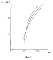
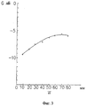
На фиг. 2 и 4 представлены диаграммы, иллюстрирующие изменение характеристики усиления в дБ в зависимости от длины L известной четвертьволновой микрополосковой антенны, а на фиг. 3 представлена диаграмма, иллюстрирующая изменение характеристики усиления в зависимости от ширины W известной четвертьволновой микрополосковой антенны. In FIG. 2 and 4 are diagrams illustrating a change in gain characteristic in dB depending on the length L of a known quarter-wave microstrip antenna, and FIG. 3 is a diagram illustrating a change in gain characteristic as a function of the width W of a known quarter-wave microstrip antenna.
Недостатком известной четвертьволновой микрополосковой антенны является то, что изменение характеристики эффективности антенны существенно зависит от толщины подложки платы печатной схемы (ППС). Большая толщина ППС приводит к более высокому усилению, но увеличивает размеры и вес антенны, вызывая неудобства для пользователя портативного устройства связи, которое становится более громоздким. В противоположность этому, если ППС имеет малую толщину, то, хотя такое устройство удобно использовать в качестве переносного, однако усиление антенны может соответственно снизиться. A disadvantage of the known quarter-wave microstrip antenna is that the change in the performance characteristics of the antenna substantially depends on the thickness of the substrate of the printed circuit board (PPS). The greater thickness of the PPP leads to higher gain, but increases the size and weight of the antenna, causing inconvenience to the user of a portable communication device, which becomes more bulky. In contrast, if the PPP has a small thickness, then although such a device is convenient to use as a portable one, however, the antenna gain may decrease accordingly.
Задачей изобретения является создание антенны, имеющей малые размеры и вес и обеспечивающей высокое усиление и эффективное применение в портативном устройстве связи. Желательно минимизировать изменения антенных характеристик, когда антенна располагается вблизи тела пользователя. The objective of the invention is to provide an antenna having small dimensions and weight and providing high gain and effective use in a portable communication device. It is desirable to minimize changes in antenna characteristics when the antenna is located near the user's body.
В возможном варианте осуществления настоящего изобретения малогабаритная антенна для портативного устройства радиосвязи содержит излучатель, выполненный в виде нагруженного несимметричного вибратора, и заземленный излучатель. Излучатель, выполненный в виде нагруженного несимметричного вибратора, содержит первый и второй проводники на подложке платы печатной схемы, причем первый проводник имеет заданную длину и ориентирован в горизонтальном направлении, а второй проводник имеет форму меандровой линии и ориентирован в вертикальном направлении. Заземленный излучатель включает в себя первый заземленный излучатель и второй заземленный излучатель на нижней части подложки платы печатной схемы, причем первый и второй заземленные излучатели симметричны относительно второго проводника. In a possible embodiment of the present invention, a small-sized antenna for a portable radio communication device comprises an emitter made in the form of a loaded asymmetric vibrator and a grounded emitter. The emitter, made in the form of a loaded asymmetric vibrator, contains the first and second conductors on the substrate of the printed circuit board, the first conductor having a predetermined length and oriented in the horizontal direction, and the second conductor has the shape of a meander line and oriented in the vertical direction. The grounded emitter includes a first grounded emitter and a second grounded emitter on the bottom of the substrate of the printed circuit board, the first and second grounded emitters being symmetrical with respect to the second conductor.
Изобретение поясняется более подробно в нижеследующем описании, иллюстрируемом чертежами, на которых представлено следующее:
фиг. 1 - диаграмма, иллюстрирующая конструкцию четвертьволновой микрополосковой антенны, известной из предшествующего уровня техники;
фиг. 2 - диаграмма, иллюстрирующая изменение характеристики усиления в зависимости от общей длины антенны по фиг. 1:
фиг. 3 - диаграмма, иллюстрирующая изменение характеристики усиления в зависимости от ширины антенны по фиг. 1;
фиг. 4 - диаграмма, иллюстрирующая изменение характеристики усиления в зависимости от длины Gz неметаллизированной части антенны по фиг. 1;
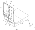
фиг. 5 - диаграмма, иллюстрирующая конструкцию антенны в виде несимметричного вибратора, соответствующей возможному варианту осуществления изобретения;
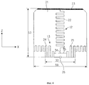
фиг. 6 - детальная схема антенны по фиг. 5;
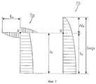
фиг. 7 - диаграмма, иллюстрирующая распределение тока нагруженного несимметричного вибратора и эквивалентного несимметричного вибратора;
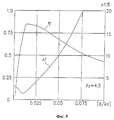
фиг. 8 - график зависимости усиления от длины антенны в виде симметричного вибратора;
фиг. 9 - график зависимости усиления от ширины антенны в виде симметричного вибратора.The invention is explained in more detail in the following description, illustrated by the drawings, which represent the following:
FIG. 1 is a diagram illustrating the construction of a quarter-wave microstrip antenna known in the art;
FIG. 2 is a diagram illustrating a change in gain characteristic as a function of the total antenna length of FIG. 1:
FIG. 3 is a diagram illustrating a change in gain characteristic as a function of the antenna width of FIG. 1;
FIG. 4 is a diagram illustrating a change in gain characteristic as a function of the length Gz of the non-metallic part of the antenna of FIG. 1;
FIG. 5 is a diagram illustrating an asymmetric vibrator antenna structure in accordance with a possible embodiment of the invention;
FIG. 6 is a detailed diagram of the antenna of FIG. 5;
FIG. 7 is a diagram illustrating a current distribution of a loaded asymmetric vibrator and an equivalent asymmetric vibrator;
FIG. 8 is a graph of gain versus antenna length in the form of a symmetrical vibrator;
FIG. 9 is a graph of gain versus antenna width in the form of a symmetrical vibrator.
На фиг. 5 схематично представлена антенна в виде несимметричного вибратора, выполненная в соответствии с возможным вариантом осуществления настоящего изобретения. Антенна показана для использования во взаимосвязи с пейджером 10 двунаправленного действия, однако изобретение может иметь и другое применение. In FIG. 5 schematically shows an antenna in the form of an asymmetric vibrator, made in accordance with a possible embodiment of the present invention. The antenna is shown for use in conjunction with a
Согласно фиг. 5, антенная система 20 содержит излучатель 12 из проводника, выполненного по форме нагруженного несимметричного вибратора, заземленный излучатель 13, выполненный по форме меандровой линии, и коаксиальную линию передачи (коаксиальный кабель) 27 для соединения излучателя 12 из проводника и заземленного излучателя 13 с ППС 11, снабженной радиочастотным усилителем мощности. Более конкретно коаксиальный кабель 27 содержит сигнальный проводник (не показан), одним концом соединенный с излучателем 12, и заземленный проводник, соединенный с заземленным излучателем 13. При этом сигнальный проводник коаксиального кабеля 27 другим своим концом соединен с сигнальным проводником портативного устройства радиосвязи (на чертеже не показано), а заземленный проводник коаксиального кабеля соединен с заземленной частью портативного устройства радиосвязи. Излучатель 12 из проводника и заземленный излучатель 13 размещены на одной основной поверхности ППС 21, которая может быть размещена в корпусе 28 антенны в форме откидной крышки. Корпус 28 в форме откидной крышки перемещается вместе с антенной системой 20 относительно корпуса пейджера 10. Т. е. антенная система 20 перемещается из положения оси Y в положение оси Z, причем корпус пейджера центрирован относительно оси X. В рабочем положении антенная система 20 находится в вертикальном положении (ориентирована в направлении Z, как показано на фиг. 5). According to FIG. 5, the
На фиг. 6 показана детальная схема антенны по фиг. 5, более конкретно показывающая ППС 21 антенной системы 20. Излучатель 12 из проводника, выполненный по форме нагруженного несимметричного вибратора, состоит из ориентированного в первом, например, в горизонтальном направлении первого проводника 23 и ориентированного во втором, например, в вертикальном направлении второго проводника 22, имеющего форму меандровой линии. Верхний конец проводника 22, ориентированного в вертикальном направлении, нагружен на проводник 23, ориентированный в горизонтальном направлении. В данном примере электрическая длина проводника 22 равна 0,49 длины волны, а электрическая длина проводника 23 равна 0,3 длины волны. Эта конструкция основана на учете того факта, что длина антенны, имеющей наивысшее усиление из эквивалентных антенн в виде вертикального несимметрического вибратора, равна 0,625 длины волны. Кроме того, в целом антенная система 20, которая использует нагрузку и форму меандровой линии и вышеуказанные длины для максимизации усиления, в особенности пригодна для использования совместно с корпусом 28 в форме прямоугольной или квадратной откидной крышки. In FIG. 6 shows a detailed diagram of the antenna of FIG. 5, more specifically showing the
Заземленный излучатель 13 размещен в нижней части ППС 21 антенной системы 20 параллельно проводнику 23, ориентированному в горизонтальном направлении. В представленной конфигурации заземленный излучатель 13 разделен на две части, симметричные относительно вертикальной части излучателя 12, а именно на первый и второй излучатели 24 и 25, симметричные относительно вертикального проводника 22 и соединенные с заземлением коаксиальной линии 27 передачи в точке 26 заземления фидера. Более конкретно первый заземленный излучатель 24 размещен с первой стороны от проводника 22, а второй заземленный излучатель 25 размещен со второй стороны от проводника 22, причем первый и второй заземленные излучатели 24, 25 соединены друг с другом. Для повышения эффективности заземленного излучателя 13 каждый из заземленных излучателей 24, 25 предпочтительно имеет электрическую длину, равную половине длины волны. Качество ППС 21 антенной системы 20, соответствующей предпочтительному варианту осуществления изобретения, может соответствовать FR-4 при толщине, например, 0,25 мм. ППС 21 может быть размещена в корпусе 28 в виде откидной крышки из поликарбоната. Конденсатор 34 и индуктивность 35 используются для согласования импедансов. The grounded
Антенна, соответствующая предпочтительному варианту осуществления изобретения, работает следующим образом. Эффективность антенны определяется эффективностью излучения, которая может быть определена с использованием следующего выражения:
![]()
где η - эффективность излучения, Rr - сопротивление излучения, Ом, RL-сопротивление потерь, Ом.An antenna according to a preferred embodiment of the invention operates as follows. The antenna efficiency is determined by the radiation efficiency, which can be determined using the following expression:
![]()
where η is the radiation efficiency, Rr is the radiation resistance, Ohm, RL is the loss resistance, Ohm.
В уравнении (1) при уменьшении длины излучателя сопротивление излучения Rr снижается. In equation (1), as the length of the emitter decreases, the radiation resistance Rr decreases.
Для увеличения эффективности излучения до значения, близкого к эффективности антенны, необходимо увеличивать длину излучателя Rr и использовать проводник с низкими потерями с низким сопротивлением RL. Таким образом, возможные варианты осуществления настоящего изобретения могут быть реализованы с использованием формы меандровой линии для проводника, чтобы уменьшить физическую длину излучателя антенны, при увеличении эффективности излучения за счет увеличения длины излучателя в функции длины волны. Наконец, усиление антенны может быть увеличено без увеличения физической длины излучателя. To increase the radiation efficiency to a value close to the antenna efficiency, it is necessary to increase the emitter length Rr and use a low-loss conductor with a low resistance RL. Thus, possible embodiments of the present invention can be implemented using the meander line shape for the conductor to reduce the physical length of the antenna emitter, while increasing the radiation efficiency by increasing the emitter length as a function of wavelength. Finally, the antenna gain can be increased without increasing the physical length of the emitter.
В статье К. Харченко "Антенный проводник в форме меандровой линии". (Радио, N 8, 1979, с. 21) описано, что по мере увеличения частоты (уменьшения периода) меандровой линии антенного проводника, полоса пропускания антенны сужается. Поэтому, как показано на фиг. 6, в данном варианте осуществления настоящего изобретения используется ориентированный в горизонтальном направлении проводник 23, нагруженный на излучатель 22, так что электрическая эквивалентная длина может быть увеличена до требуемого значения без избыточного сужения ширины полосы антенны. Достигаемый эффект заключается в том, что антенна работает аналогично антенне с излучателем увеличенной длины, тем самым обеспечивая повышение усиления антенны. In the article by K. Kharchenko "Antenna conductor in the form of a meander line". (Radio, No. 8, 1979, p. 21) describes that as the frequency (decreasing period) of the meander line of the antenna conductor increases, the antenna bandwidth narrows. Therefore, as shown in FIG. 6, in this embodiment of the present invention, a horizontally oriented
На фиг. 7 представлен график, иллюстрирующий распределение тока в нагруженном несимметричном вибраторе и в эквивалентном несимметричном вибраторе, причем часть 7а графика иллюстрирует нагруженный несимметричный вибратор и распределение тока в нем, а часть 7b графика иллюстрирует распределение тока в антенне в виде эквивалентного несимметричного вибратора. Желательно получить хорошее распределение тока в ориентированном в вертикальном направлении проводнике антенны. Таким образом, антенна работает аналогично тому, как при увеличении длины на Δ lv, при использовании горизонтального проводника (нагруженный излучатель), что видно из следующего выражения (2):
L v eqv = lv + Δ lv,
где Δ lv - увеличение длины эквивалентного вертикального проводника.In FIG. 7 is a graph illustrating a current distribution in a loaded asymmetric vibrator and in an equivalent asymmetric vibrator, wherein part 7a of the graph illustrates the loaded asymmetric vibrator and the current distribution in it, and part 7b of the graph illustrates the current distribution in the antenna as an equivalent asymmetric vibrator. It is desirable to obtain a good current distribution in a vertically oriented antenna conductor. Thus, the antenna works in the same way as when increasing the length by Δ lv, using a horizontal conductor (loaded emitter), which can be seen from the following expression (2):
L v eqv = lv + Δ lv,
where Δ lv is the increase in the length of the equivalent vertical conductor.
Для нагруженной антенны в виде несимметричного вибратора, если только значение тока в конечной точке "А" (см. фиг. 7), ориентированного в вертикальном направлении проводника 22, не становится равным нулю, указанное значение определяется реактивным импедансом ориентированного в горизонтальном направлении проводника 23 антенны в виде нагруженного несимметричного вибратора. Только если входной реактивный импеданс нагруженного излучателя в точке А равен входному реактивному импедансу в точке В эквивалентного несимметричного вибратора, то ориентированный в вертикальном направлении проводник антенны может быть увеличен на Δ l. For a loaded antenna in the form of an asymmetric vibrator, if only the current value at the end point "A" (see Fig. 7) oriented in the vertical direction of the
В данной ситуации входные реактивные импедансы XA и XB нагруженного излучателя в положениях A и B таковы, как представлено ниже в выражениях (3) и (4):
![]()
где 1H - длина "плеча", ориентированного в горизонтальном направлении проводника нагруженного несимметричного вибратора (т. е. примерно половина полной горизонтальной длины всего проводника 23), a ZOH - собственный импеданс ориентированного в горизонтальном направлении проводника нагруженного несимметричного вибратора;
![]()
где ZOV- собственный импеданс ориентированного в вертикальном направлении проводника нагруженного несимметричного вибратора.In this situation, the input reactive impedances XA and XB of the loaded emitter in positions A and B are as shown below in expressions (3) and (4):
![]()
where 1H is the length of the "shoulder" oriented in the horizontal direction of the conductor of the loaded asymmetric vibrator (that is, approximately half the total horizontal length of the entire conductor 23), and ZOH is the intrinsic impedance of the horizontal oriented conductor of the loaded asymmetric vibrator;
![]()
where ZOV is the intrinsic impedance of a vertically oriented conductor of a loaded asymmetric vibrator.
Кроме того, если два входных реактивных импеданса XA и XB равны друг другу, то Δlv можно получить из выражения (5) в следующем виде:
![]()
В результате, lv eqv равно сумме lv и Δ lv. Т. е. lv eqv = lv - Δ lv. Иными словами, можно видеть, что физическая длина антенны в виде ненагруженного вибратора увеличивается на Δ lv. Кроме того, корпус оконечного пользовательского устройства, покрытого металлической пленкой, или заземление установленной в нем ППС может служить в качестве заземления для всей антенны в виде несимметричного вибратора. Следовательно, если пользователь берет свое оконечное устройство в руки, эффективность излучения может снижаться, несмотря на то, что его заземление служит в качестве заземленного излучателя (см. "Mobile Antenna Systems Handbook", K. Fujimoto, J. R. James, Artech House, Boston-London, 1994, pp. 217-243).In addition, if the two input reactive impedances XA and XB are equal to each other, then Δlv can be obtained from expression (5) in the following form:
![]()
As a result, lv eqv is equal to the sum of lv and Δ lv. That is, lv eqv = lv - Δ lv. In other words, it can be seen that the physical length of the antenna in the form of an unloaded vibrator increases by Δ lv. In addition, the housing of the terminal user device covered with a metal film, or the grounding of the PPP installed in it, can serve as grounding for the entire antenna in the form of an asymmetric vibrator. Therefore, if the user takes his terminal device in his hands, the radiation efficiency may decrease, even though his grounding serves as a grounded emitter (see "Mobile Antenna Systems Handbook", K. Fujimoto, JR James, Artech House, Boston- London, 1994, pp. 217-243).
Первый и второй заземленные излучатели 24 и 25 выполнены в предпочтительном варианте осуществления изобретения так, чтобы минимизировать эффект влияния тела пользователя на излучение антенны в виде несимметричного вибратора, когда пользовательское оконечное устройство располагается в непосредственной близости от тела человека. Поскольку ток антенны отделен от заземления пейджера 10 двунаправленного действия, то снижение эффективности излучения может быть минимизировано в положении, когда пользователь держит это устройство в руке. Также, когда пользователь действительно использует оконечное устройство, первый и второй заземленные излучатели 24 и 25 размещаются на ППС 21 антенны, установленной на верхней поверхности пейджера 10 двунаправленного действия, наиболее удаленной от тела пользователя в рабочем положении пейджера. The first and second grounded
Излучение от первого и от второго заземленных излучателей 24 и 25 зависит от закона изменения напряжения сигнала. Переменное напряжение сигнала может сформировать паразитный ток, протекающий вдоль поверхности (заземления) коаксиальной линии передачи 27, тем самым изменяя такие характеристики антенны, как диаграмма направленности, входной импеданс и усиление. Для исключения изменения таких характеристик первый и второй излучатели 24 и 25 противоположны один другому и центрированы относительно оси Z антенны на ППС 21, а электрическая длина каждого из них равна L = (2n - 1) λ/4, где n - положительная постоянная. Т. е. электрическая длина каждого из заземленных излучателей 24 и 25 устанавливается равной нечетному кратному четверти длины волны. Если электрическая длина каждого из заземленных излучателей 24 и 25 одинакова, то паразитный ток, протекающий от поверхности заземленного излучателя 26 к его заземлению, может быть минимизирован. Следовательно, будет иметь место весьма незначительное ухудшение характеристик антенны и эффективности излучения под влиянием близко расположенного тела пользователя, даже если заземление пейджера 10 двунаправленного действия находится в непосредственной близости от него. Radiation from the first and second grounded
Из фиг. 2-4 следует, что характеристика усиления четвертьволновой микрополосковой антенны является функцией длин L и Gz и ширины W антенны и что ее характеристика усиления является более низкой по сравнению с характеристикой усиления антенны в виде симметричного вибратора. На фиг. 8 представлена зависимость усиления от длины антенны в виде симметричного вибратора, которую можно сравнить с графиками, показанными на фиг. 2-4. From FIG. 2-4 it follows that the gain characteristic of the quarter-wave microstrip antenna is a function of the lengths L and Gz and the width W of the antenna and that its gain characteristic is lower than the gain of the antenna in the form of a symmetrical vibrator. In FIG. 8 shows the dependence of the gain on the length of the antenna in the form of a symmetrical vibrator, which can be compared with the graphs shown in FIG. 2-4.
Сравним антенну, соответствующую варианту осуществления настоящего изобретения, с известной антенной. Если параметры антенны, соответствующей настоящему изобретению (L = 47,3 мм; εγ = 4,5 мм; f = 916 МГц), адаптировать к известной антенне, то можно осуществить указанное сравнение. Сравнение усиления антенны, соответствующей настоящему изобретению, и известной антенны состоит в следующем.Compare an antenna according to an embodiment of the present invention with a known antenna. If the parameters of the antenna of the present invention (L = 47.3 mm; ε γ = 4.5 mm; f = 916 MHz) are adapted to a known antenna, then this comparison can be made. A comparison of the gain of the antenna of the present invention and the known antenna is as follows.
Если для конструкции, иллюстрируемой фиг. 1, предположить, что b= λs /4, L = 47,3 мм, εγ = 4,5 мм; f = 916 МГц и d = 1.2 мм, то параметры λs., b, Gr определяются, как показано ниже:

b = λs/4 = 38,6 мм, (7)
Gz = L - b = 8,7 мм.If for the construction illustrated in FIG. 1, assume that b = λ s / 4, L = 47.3 mm, ε γ = 4.5 mm; f = 916 MHz and d = 1.2 mm, then the parameters λ s ., b, Gr are determined as shown below:
b = λs / 4 = 38.6 mm, (7)
Gz = L - b = 8.7 mm.
С учетом фиг. 2 и 4, для случая, когда L= 47.3 мм и Gz = 8,7 мм, усиление, как показано на этих фигурах, примерно равно - 12,5 dBd (-10,35 dBi). Антенна, используемая в рассматриваемом варианте осуществления, имеет электрическую длину 0,625 λ. Для данного случая усиление равно примерно 3dBd (5,15 dBi), как видно из фиг. 8. Таким образом, в известной антенне усиление может ухудшиться примерно на 15 дБ. (Отметим, что графики, приведенные на фиг. 8 и 9, относятся к антенне в виде симметричного вибратора. Однако усиление антенны в виде несимметричного вибратора по существу то же самое, что и для эквивалентного симметричного вибратора. Таким образом, можно считать, что фиг. 8 и 9 представляют усиление антенны в виде несимметричного вибратора, соответствующего настоящему изобретению). In view of FIG. 2 and 4, for the case when L = 47.3 mm and Gz = 8.7 mm, the gain, as shown in these figures, is approximately equal to –12.5 dBd (-10.35 dBi). The antenna used in this embodiment has an electric length of 0.625 λ. For this case, the gain is approximately 3dBd (5.15 dBi), as can be seen from FIG. 8. Thus, in a known antenna, the gain can be degraded by about 15 dB. (Note that the graphs shown in FIGS. 8 and 9 refer to an antenna in the form of a symmetrical vibrator. However, the antenna gain in the form of an asymmetric vibrator is essentially the same as for an equivalent symmetric vibrator. Thus, it can be assumed that FIG. 8 and 9 represent the antenna gain in the form of an asymmetric vibrator according to the present invention).
Другой проблемой для предшествующего уровня техники является то, что характеристика эффективности η четвертьволновой микрополосковой антенны изменяется в функции толщины d ППС. Если технические характеристики антенны, используемой в настоящем изобретении, адаптировать к характеристикам известной антенны (L = 47,3 мм, εγ = 4,5 мм, f = 916 МГц и d = 0.25 мм), то усиление соответственно изменениям толщины d может быть представлено, как показано на фиг. 9. Усиление антенны с вышеуказанными параметрами равно примерно - 12.5 dBd. Здесь толщина d = 1,2 мм, при этом, как показано на фиг. 9, эффективность антенны определяется следующими параметрами, представленными в выражении (9):
F= c/λ0;
λ0 = c/f = 3•10/916•10= 327,5 мм;
F = 1,2/327,5= 0,003664.Another problem for the prior art is that the performance characteristic η of the quarter-wave microstrip antenna changes as a function of the thickness d of the PPP. If the technical characteristics of the antenna used in the present invention are adapted to the characteristics of the known antenna (L = 47.3 mm, ε γ = 4.5 mm, f = 916 MHz and d = 0.25 mm), then the gain corresponding to changes in the thickness d can be represented as shown in FIG. 9. The gain of the antenna with the above parameters is approximately - 12.5 dBd. Here, the thickness d = 1.2 mm, while, as shown in FIG. 9, the antenna efficiency is determined by the following parameters presented in expression (9):
F = c / λ 0 ;
λ 0 = c / f = 3 • 10/916 • 10 = 327.5 mm;
F = 1.2 / 327.5 = 0.003664.
Как показано на фиг. 9, если F = d/ λ0 = 0,003664, то эффективность антенны составляет около 50%. Если толщина d ППС равна 0,25 мм, F = 0,000736 и эффективность антенны примерно равна 4,5%.As shown in FIG. 9, if F = d / λ 0 = 0.003664, then the antenna efficiency is about 50%. If the thickness d of the PPP is 0.25 mm, F = 0.000736 and the antenna efficiency is approximately 4.5%.
Следовательно, если d = 1,2 мм, η примерно равно 50%. Если d = 0,25 мм, η примерно равно 4,5%. В случае ППС большой толщины (d = 1,2 мм) значение усиления примерно в 11 раз превышает значение усиления для случая тонкой ППС (d = 0,25 мм). При вычислении усиления с использованием вышеуказанного результата усиление антенны будет определяться согласно выражению (10) следующим образом:
G = -12,5 dBd - 10 log11 = -22,9 dBd (10).Therefore, if d = 1.2 mm, η is approximately equal to 50%. If d = 0.25 mm, η is approximately equal to 4.5%. In the case of PPPs of large thickness (d = 1.2 mm), the gain value is approximately 11 times higher than the gain value for the case of thin PPPs (d = 0.25 mm). When calculating the gain using the above result, the antenna gain will be determined according to expression (10) as follows:
G = -12.5 dBd - 10 log11 = -22.9 dBd (10).
Из приведенного выше выражения (10), что усиление снижается примерно на 10 дБ по сравнению со случаем, когда d = 1,2 мм. Кроме того, усиление снижается примерно на 25 дБ по сравнению с усилением антенны в виде симметричного вибратора. From the above expression (10), that the gain decreases by about 10 dB compared with the case when d = 1.2 mm. In addition, the gain is reduced by about 25 dB compared with the gain of the antenna in the form of a symmetrical vibrator.
Поскольку антенная система, соответствующая настоящему изобретению, может быть реализована с использованием ППС малой толщины, то она будет иметь малый вес, будет удобной в применении ввиду простоты установки на верхней поверхности пользовательского оконечного устройства (например, пейджера). Кроме того, поскольку вертикальный излучатель, размещенный на ППС, выполнен в форме меандровой линии, то физическая длина уменьшена, что позволяет получить наилучшие электрические характеристики для ограниченных размеров антенны. Кроме того, поскольку на верхнем конце ориентированного в вертикальном направлении излучателя использован другой ориентированный в горизонтальном направлении излучатель, и ориентированный в вертикальном направлении излучатель эквивалентным образом увеличен, то это приводит к увеличению усиления антенны. К тому же, поскольку ориентированные в вертикальном и горизонтальном направлении излучатели и заземленный излучатель выполнены на одной ППС малой толщины, это упрощает изготовление антенны. Заземленный излучатель препятствует протеканию антенного тока в заземление оконечного устройства. Изменения характеристик антенны могут быть минимизированы в зависимости от изменения состояния заземления оконечного устройства, например, как результат контакта с телом пользователя. Следовательно, изобретение обеспечивает создание антенн с устойчивыми высокими характеристиками. Since the antenna system according to the present invention can be implemented using small thickness PPPs, it will have a low weight and will be convenient to use due to the ease of installation on the upper surface of a user terminal device (for example, a pager). In addition, since the vertical radiator located on the faculty is made in the form of a meander line, the physical length is reduced, which makes it possible to obtain the best electrical characteristics for limited antenna sizes. In addition, since another horizontally oriented radiator is used at the upper end of the vertical oriented emitter, and the vertical oriented emitter is equivalently increased, this leads to an increase in antenna gain. In addition, since the emitters oriented in the vertical and horizontal directions and the grounded emitter are made on the same PPS of small thickness, this simplifies the manufacture of the antenna. A grounded emitter prevents the antenna current from flowing into the ground of the terminal device. Changes in the characteristics of the antenna can be minimized depending on the change in the grounding state of the terminal device, for example, as a result of contact with the user's body. Therefore, the invention provides the creation of antennas with stable high performance.
Claims (14)
Applications Claiming Priority (3)
| Application Number | Priority Date | Filing Date | Title |
|---|---|---|---|
| KR1996-52132 | 1996-11-05 | ||
| KR96-52132 | 1996-11-05 | ||
| KR1019960052132A KR100193851B1 (en) | 1996-11-05 | 1996-11-05 | Small antenna of portable radio |
Publications (2)
| Publication Number | Publication Date |
|---|---|
| RU99112172A RU99112172A (en) | 2001-04-10 |
| RU2178604C2 true RU2178604C2 (en) | 2002-01-20 |
Family
ID=19480842
Family Applications (1)
| Application Number | Title | Priority Date | Filing Date |
|---|---|---|---|
| RU99112172/09A RU2178604C2 (en) | 1996-11-05 | 1997-09-08 | Small-size antenna for portable radio communication device |
Country Status (11)
| Country | Link |
|---|---|
| US (1) | US5936587A (en) |
| EP (1) | EP0937313B1 (en) |
| JP (1) | JP2000508498A (en) |
| KR (1) | KR100193851B1 (en) |
| CN (1) | CN1108643C (en) |
| AU (1) | AU716524B2 (en) |
| BR (1) | BR9712738A (en) |
| DE (1) | DE69732975T2 (en) |
| IL (1) | IL121693A (en) |
| RU (1) | RU2178604C2 (en) |
| WO (1) | WO1998020578A1 (en) |
Cited By (2)
| Publication number | Priority date | Publication date | Assignee | Title |
|---|---|---|---|---|
| RU2637365C2 (en) * | 2015-06-30 | 2017-12-04 | Общество с ограниченной ответственностью "Научно-производственное предприятие "Технологии и системы радиомониторинга" | Small-size wideband antenna |
| US9887452B2 (en) | 2011-11-01 | 2018-02-06 | Nec Corporation | Artificial satellite with integrated antenna |
Families Citing this family (86)
| Publication number | Priority date | Publication date | Assignee | Title |
|---|---|---|---|---|
| US7019695B2 (en) * | 1997-11-07 | 2006-03-28 | Nathan Cohen | Fractal antenna ground counterpoise, ground planes, and loading elements and microstrip patch antennas with fractal structure |
| GB2323476B (en) * | 1997-03-20 | 2002-01-16 | David Ganeshmoorthy | Communication antenna and equipment |
| KR19990034478A (en) * | 1997-10-29 | 1999-05-15 | 구자홍 | Receiver for mobile communication terminal |
| SE511131C2 (en) * | 1997-11-06 | 1999-08-09 | Ericsson Telefon Ab L M | Portable electronic communication device with multi-band antenna system |
| SE511068C2 (en) * | 1997-11-06 | 1999-08-02 | Ericsson Telefon Ab L M | Portable electronic communication device with dual band antenna system |
| US6107967A (en) * | 1998-07-28 | 2000-08-22 | Wireless Access, Inc. | Billboard antenna |
| US6147653A (en) * | 1998-12-07 | 2000-11-14 | Wallace; Raymond C. | Balanced dipole antenna for mobile phones |
| GB2344969B (en) * | 1998-12-19 | 2003-02-26 | Nec Technologies | Mobile phone with incorporated antenna |
| US6232924B1 (en) | 1998-12-21 | 2001-05-15 | Ericsson Inc. | Flat blade antenna and flip mounting structures |
| US6301489B1 (en) | 1998-12-21 | 2001-10-09 | Ericsson Inc. | Flat blade antenna and flip engagement and hinge configurations |
| US6249688B1 (en) | 1998-12-21 | 2001-06-19 | Ericcson Inc. | Antenna electrical coupling configurations |
| WO2000052784A1 (en) * | 1999-03-01 | 2000-09-08 | Siemens Aktiengesellschaft | Integrable multiband antenna |
| USD431558S (en) * | 1999-03-01 | 2000-10-03 | Ericsson Inc. | Flip and blade antenna for radiotelephone |
| US6977808B2 (en) * | 1999-05-14 | 2005-12-20 | Apple Computer, Inc. | Display housing for computing device |
| US6357887B1 (en) | 1999-05-14 | 2002-03-19 | Apple Computers, Inc. | Housing for a computing device |
| US6198442B1 (en) * | 1999-07-22 | 2001-03-06 | Ericsson Inc. | Multiple frequency band branch antennas for wireless communicators |
| DE10084893T1 (en) * | 1999-08-18 | 2002-10-31 | Ericsson Inc | Dual Band Butterfly / meander antenna |
| CN101188325B (en) | 1999-09-20 | 2013-06-05 | 弗拉克托斯股份有限公司 | Multi-level antenna |
| US6404394B1 (en) * | 1999-12-23 | 2002-06-11 | Tyco Electronics Logistics Ag | Dual polarization slot antenna assembly |
| WO2001054225A1 (en) | 2000-01-19 | 2001-07-26 | Fractus, S.A. | Space-filling miniature antennas |
| JP3640595B2 (en) * | 2000-05-18 | 2005-04-20 | シャープ株式会社 | Multilayer pattern antenna and wireless communication apparatus including the same |
| US6690331B2 (en) | 2000-05-24 | 2004-02-10 | Bae Systems Information And Electronic Systems Integration Inc | Beamforming quad meanderline loaded antenna |
| US6323814B1 (en) * | 2000-05-24 | 2001-11-27 | Bae Systems Information And Electronic Systems Integration Inc | Wideband meander line loaded antenna |
| AU2001275024A1 (en) | 2000-05-31 | 2001-12-11 | Bae Systems Information And Electronic Systems Integration, Inc. | Scanning, circularly polarized varied impedance transmission line antenna |
| US6480158B2 (en) | 2000-05-31 | 2002-11-12 | Bae Systems Information And Electronic Systems Integration Inc. | Narrow-band, crossed-element, offset-tuned dual band, dual mode meander line loaded antenna |
| US6344825B1 (en) * | 2000-08-31 | 2002-02-05 | Inventec Corporation | Antenna apparatus for portable electronic device |
| EP1198027B1 (en) * | 2000-10-12 | 2006-05-31 | The Furukawa Electric Co., Ltd. | Small antenna |
| WO2002060007A1 (en) * | 2001-01-25 | 2002-08-01 | Bae Systems Information And Electronic Systems Integration Inc. | Meander line loaded tunable patch antenna |
| US7023909B1 (en) | 2001-02-21 | 2006-04-04 | Novatel Wireless, Inc. | Systems and methods for a wireless modem assembly |
| US6842148B2 (en) * | 2001-04-16 | 2005-01-11 | Skycross, Inc. | Fabrication method and apparatus for antenna structures in wireless communications devices |
| DE60215391T2 (en) * | 2001-06-15 | 2007-10-25 | Apple Computer, Inc., Cupertino | ACTIVE COMPUTER HOUSING |
| US7766517B2 (en) | 2001-06-15 | 2010-08-03 | Apple Inc. | Active enclosure for computing device |
| US7452098B2 (en) * | 2001-06-15 | 2008-11-18 | Apple Inc. | Active enclosure for computing device |
| US7071889B2 (en) | 2001-08-06 | 2006-07-04 | Actiontec Electronics, Inc. | Low frequency enhanced frequency selective surface technology and applications |
| US9755314B2 (en) | 2001-10-16 | 2017-09-05 | Fractus S.A. | Loaded antenna |
| US6567056B1 (en) * | 2001-11-13 | 2003-05-20 | Intel Corporation | High isolation low loss printed balun feed for a cross dipole structure |
| US6882316B2 (en) | 2002-01-23 | 2005-04-19 | Actiontec Electronics, Inc. | DC inductive shorted patch antenna |
| JP4051346B2 (en) * | 2002-01-23 | 2008-02-20 | 加賀電子株式会社 | DC induction short patch antenna |
| AU2003245383A1 (en) * | 2002-06-03 | 2003-12-19 | Mendolia, Greg, S. | Combined emi shielding and internal antenna for mobile products |
| US7184800B2 (en) * | 2002-10-15 | 2007-02-27 | Kyocera Wireless Corp. | Printed stubby unbalanced dipole antenna |
| JP2006512691A (en) | 2002-10-22 | 2006-04-13 | アイシス テクノロジーズ | Non-peripheral processing control module with improved heat dissipation characteristics |
| KR101499826B1 (en) | 2002-10-22 | 2015-03-10 | 제이슨 에이. 설리반 | Robust customizable computing system, processing control unit, and wireless computing network apparatus |
| EP1557074A4 (en) | 2002-10-22 | 2010-01-13 | Sullivan Jason | Robust customizable computer processing system |
| JP2006510321A (en) * | 2002-12-22 | 2006-03-23 | フラクタス・ソシエダッド・アノニマ | Multiband monopole antenna for mobile communication devices |
| JP3833609B2 (en) * | 2002-12-27 | 2006-10-18 | 本田技研工業株式会社 | Car antenna |
| FI115173B (en) * | 2002-12-31 | 2005-03-15 | Filtronic Lk Oy | Antenna for a collapsible radio |
| FR2850966B1 (en) | 2003-02-10 | 2005-03-18 | Rhodia Polyamide Intermediates | PROCESS FOR PRODUCING DINITRIL COMPOUNDS |
| DE10311040A1 (en) * | 2003-03-13 | 2004-10-07 | Kathrein-Werke Kg | antenna array |
| FR2854891B1 (en) | 2003-05-12 | 2006-07-07 | Rhodia Polyamide Intermediates | PROCESS FOR PREPARING DINITRILES |
| US7336243B2 (en) * | 2003-05-29 | 2008-02-26 | Sky Cross, Inc. | Radio frequency identification tag |
| KR100450878B1 (en) * | 2003-06-13 | 2004-10-13 | 주식회사 에이스테크놀로지 | Built-in antenna with a center feed structure for wireless terminal |
| WO2005027267A1 (en) * | 2003-09-09 | 2005-03-24 | National Institute Of Information And Communications Technology | Wide band antenna common to a plurality of frequencies |
| EP1709704A2 (en) | 2004-01-30 | 2006-10-11 | Fractus, S.A. | Multi-band monopole antennas for mobile communications devices |
| US7193565B2 (en) * | 2004-06-05 | 2007-03-20 | Skycross, Inc. | Meanderline coupled quadband antenna for wireless handsets |
| US7408512B1 (en) * | 2005-10-05 | 2008-08-05 | Sandie Corporation | Antenna with distributed strip and integrated electronic components |
| EP2322503B1 (en) | 2005-10-18 | 2014-12-31 | Invista Technologies S.à.r.l. | Process of making 3-aminopentanenitrile |
| US20070164909A1 (en) * | 2006-01-13 | 2007-07-19 | Ogawa Harry K | Embedded antenna of a mobile device |
| BRPI0709313A2 (en) | 2006-03-17 | 2011-07-05 | Invista Tech Sarl | separation method and method for the preparation of triorganophosphites |
| US20070257842A1 (en) * | 2006-05-02 | 2007-11-08 | Air2U Inc. | Coupled-fed antenna device |
| GB2439110B (en) * | 2006-06-13 | 2009-08-19 | Thales Holdings Uk Plc | An ultra wideband antenna |
| US7919646B2 (en) | 2006-07-14 | 2011-04-05 | Invista North America S.A R.L. | Hydrocyanation of 2-pentenenitrile |
| US8738103B2 (en) | 2006-07-18 | 2014-05-27 | Fractus, S.A. | Multiple-body-configuration multimedia and smartphone multifunction wireless devices |
| US20080143606A1 (en) * | 2006-12-18 | 2008-06-19 | Motorola, Inc. | Antenna assembly and communications assembly |
| US8906334B2 (en) | 2007-05-14 | 2014-12-09 | Invista North America S.A R.L. | High efficiency reactor and process |
| WO2008157218A1 (en) | 2007-06-13 | 2008-12-24 | Invista Technologies S.A.R.L. | Process for improving adiponitrile quality |
| TW200924281A (en) * | 2007-11-22 | 2009-06-01 | Quanta Comp Inc | Built-in antenna |
| EP2229353B1 (en) | 2008-01-15 | 2018-01-03 | INVISTA Textiles (U.K.) Limited | Hydrocyanation of pentenenitriles |
| CN101910119B (en) | 2008-01-15 | 2013-05-29 | 因温斯特技术公司 | Process for making and refining 3-pentenenitrile, and for refining 2-methyl-3-butenenitrile |
| US8247621B2 (en) | 2008-10-14 | 2012-08-21 | Invista North America S.A.R.L. | Process for making 2-secondary-alkyl-4,5-di-(normal-alkyl)phenols |
| KR20120047251A (en) | 2009-08-07 | 2012-05-11 | 인비스타 테크놀러지스 에스.에이.알.엘. | Hydrogenation and esterification to form diesters |
| WO2012109393A1 (en) | 2011-02-08 | 2012-08-16 | Henry Cooper | High gain frequency step horn antenna |
| US9478868B2 (en) | 2011-02-09 | 2016-10-25 | Xi3 | Corrugated horn antenna with enhanced frequency range |
| KR101297332B1 (en) * | 2012-02-28 | 2013-08-14 | 에이트론(주) | Antenna for multiple resonance |
| CN103296422A (en) * | 2012-03-01 | 2013-09-11 | 华硕电脑股份有限公司 | Electronic device |
| WO2014047211A1 (en) * | 2012-09-19 | 2014-03-27 | Wireless Research Development | Pentaband antenna |
| US9413069B2 (en) * | 2013-02-25 | 2016-08-09 | Taoglas Group Holdings Limited | Compact, multi-port, Wi-Fi dual band MIMO antenna system |
| US9450309B2 (en) | 2013-05-30 | 2016-09-20 | Xi3 | Lobe antenna |
| KR20160113196A (en) * | 2014-01-24 | 2016-09-28 | 더 안테나 컴퍼니 인터내셔널 엔.브이. | Antenna module, antenna and mobile device comprising such an antenna module |
| USD760205S1 (en) * | 2014-03-28 | 2016-06-28 | Lorom Industrial Co., Ltd. | Antenna for glass |
| USD815621S1 (en) | 2016-07-11 | 2018-04-17 | Taoglas Group Holdings Limited | Antenna |
| US10840589B2 (en) | 2016-09-02 | 2020-11-17 | Taoglas Group Holdings Limited | Multi-band MIMO panel antennas |
| FR3055744B1 (en) | 2016-09-02 | 2022-01-21 | Taoglas Group Holdings Ltd | MULTI-BAND MIMO FLAT ANTENNAS |
| CN110323553B (en) * | 2019-04-01 | 2021-07-16 | 深圳三星通信技术研究有限公司 | Antenna radiation unit and antenna |
| CN110828990A (en) * | 2019-10-31 | 2020-02-21 | 深圳市道通智能航空技术有限公司 | Antenna |
| TWI738343B (en) * | 2020-05-18 | 2021-09-01 | 為昇科科技股份有限公司 | Meander antenna structure |
| WO2023159345A1 (en) * | 2022-02-22 | 2023-08-31 | 京东方科技集团股份有限公司 | Antenna |
Family Cites Families (11)
| Publication number | Priority date | Publication date | Assignee | Title |
|---|---|---|---|---|
| US4313121A (en) * | 1980-03-13 | 1982-01-26 | The United States Of America As Represented By The Secretary Of The Army | Compact monopole antenna with structured top load |
| US4684953A (en) * | 1984-01-09 | 1987-08-04 | Mcdonnell Douglas Corporation | Reduced height monopole/crossed slot antenna |
| US4644366A (en) * | 1984-09-26 | 1987-02-17 | Amitec, Inc. | Miniature radio transceiver antenna |
| JP2515624B2 (en) * | 1990-11-01 | 1996-07-10 | 原田工業株式会社 | Antenna coupling circuit |
| GB9102935D0 (en) * | 1991-02-12 | 1991-03-27 | Shaye Communications Ltd | Improvements in and relating to antennae |
| DE4113277C2 (en) * | 1991-04-19 | 1996-08-08 | Hagenuk Telecom Gmbh | Antenna for a mobile phone |
| JPH0690108A (en) * | 1992-09-07 | 1994-03-29 | Nippon Telegr & Teleph Corp <Ntt> | Compact antenna and manufacture of the same |
| AT398532B (en) * | 1992-09-22 | 1994-12-27 | Linser Franz Dr | Power training apparatus |
| DE4410618A1 (en) * | 1994-03-26 | 1995-09-28 | Reitter & Schefenacker Gmbh | Exterior rear view mirror for motor vehicles |
| WO1996027219A1 (en) * | 1995-02-27 | 1996-09-06 | The Chinese University Of Hong Kong | Meandering inverted-f antenna |
| US5706016A (en) * | 1996-03-27 | 1998-01-06 | Harrison, Ii; Frank B. | Top loaded antenna |
-
1996
- 1996-11-05 KR KR1019960052132A patent/KR100193851B1/en not_active IP Right Cessation
-
1997
- 1997-06-30 US US08/884,812 patent/US5936587A/en not_active Expired - Lifetime
- 1997-09-03 IL IL12169397A patent/IL121693A/en not_active IP Right Cessation
- 1997-09-08 AU AU41377/97A patent/AU716524B2/en not_active Ceased
- 1997-09-08 WO PCT/KR1997/000166 patent/WO1998020578A1/en active IP Right Grant
- 1997-09-08 CN CN97199577A patent/CN1108643C/en not_active Expired - Fee Related
- 1997-09-08 EP EP97939247A patent/EP0937313B1/en not_active Expired - Lifetime
- 1997-09-08 BR BR9712738-8A patent/BR9712738A/en not_active Application Discontinuation
- 1997-09-08 RU RU99112172/09A patent/RU2178604C2/en not_active IP Right Cessation
- 1997-09-08 JP JP10521233A patent/JP2000508498A/en active Pending
- 1997-09-08 DE DE69732975T patent/DE69732975T2/en not_active Expired - Fee Related
Cited By (2)
| Publication number | Priority date | Publication date | Assignee | Title |
|---|---|---|---|---|
| US9887452B2 (en) | 2011-11-01 | 2018-02-06 | Nec Corporation | Artificial satellite with integrated antenna |
| RU2637365C2 (en) * | 2015-06-30 | 2017-12-04 | Общество с ограниченной ответственностью "Научно-производственное предприятие "Технологии и системы радиомониторинга" | Small-size wideband antenna |
Also Published As
| Publication number | Publication date |
|---|---|
| DE69732975T2 (en) | 2005-09-08 |
| CN1237278A (en) | 1999-12-01 |
| EP0937313B1 (en) | 2005-04-06 |
| CN1108643C (en) | 2003-05-14 |
| EP0937313A1 (en) | 1999-08-25 |
| AU4137797A (en) | 1998-05-29 |
| KR19980034169A (en) | 1998-08-05 |
| IL121693A0 (en) | 1998-02-22 |
| US5936587A (en) | 1999-08-10 |
| DE69732975D1 (en) | 2005-05-12 |
| AU716524B2 (en) | 2000-02-24 |
| IL121693A (en) | 2000-06-01 |
| BR9712738A (en) | 1999-10-19 |
| WO1998020578A1 (en) | 1998-05-14 |
| JP2000508498A (en) | 2000-07-04 |
| KR100193851B1 (en) | 1999-06-15 |
Similar Documents
| Publication | Publication Date | Title |
|---|---|---|
| RU2178604C2 (en) | Small-size antenna for portable radio communication device | |
| US4700194A (en) | Small antenna | |
| US7079081B2 (en) | Slotted cylinder antenna | |
| US6768476B2 (en) | Capacitively-loaded bent-wire monopole on an artificial magnetic conductor | |
| US6288682B1 (en) | Directional antenna assembly | |
| US7205944B2 (en) | Methods and apparatus for implementation of an antenna for a wireless communication device | |
| EP0070150B1 (en) | Antenna arrangement for personal radio transceivers | |
| US20030043075A1 (en) | Broad band and multi-band antennas | |
| US7079077B2 (en) | Methods and apparatus for implementation of an antenna for a wireless communication device | |
| US5914695A (en) | Omnidirectional dipole antenna | |
| US4584585A (en) | Two element low profile antenna | |
| WO2003041217A2 (en) | Multiband antenna formed of superimposed compressed loops | |
| JP2001203521A (en) | Flat microstrip patch antenna | |
| JP3255803B2 (en) | Mobile radio antenna | |
| JP3937935B2 (en) | Wireless communication card for information processing equipment | |
| JP2004015500A (en) | Antenna element and antenna device | |
| JPH01206705A (en) | Non-directional micro-strip antenna | |
| KR100287997B1 (en) | Plane monopole antenna for wiress local area network | |
| RU2036540C1 (en) | Vertical wide-band aerial | |
| JPH08213832A (en) | Antenna for mobile radio system | |
| JP2001358516A (en) | Chip type antenna element and antenna device as well as communication apparatus mounting the same | |
| JPS6284606A (en) | Antenna |
Legal Events
| Date | Code | Title | Description |
|---|---|---|---|
| MM4A | The patent is invalid due to non-payment of fees |
Effective date: 20090909 |