RU215263U1 - Balance spring suspension - Google Patents
Balance spring suspension Download PDFInfo
- Publication number
- RU215263U1 RU215263U1 RU2022123047U RU2022123047U RU215263U1 RU 215263 U1 RU215263 U1 RU 215263U1 RU 2022123047 U RU2022123047 U RU 2022123047U RU 2022123047 U RU2022123047 U RU 2022123047U RU 215263 U1 RU215263 U1 RU 215263U1
- Authority
- RU
- Russia
- Prior art keywords
- brackets
- fixed
- rods
- axle
- shaped
- Prior art date
Links
- 239000000725 suspension Substances 0.000 title claims abstract description 18
- 239000003381 stabilizer Substances 0.000 claims abstract description 6
- 238000004642 transportation engineering Methods 0.000 abstract description 2
- 239000002184 metal Substances 0.000 description 4
- 238000000034 method Methods 0.000 description 2
- 230000035939 shock Effects 0.000 description 2
- 125000006850 spacer group Chemical group 0.000 description 2
- 239000006096 absorbing agent Substances 0.000 description 1
- 239000003638 chemical reducing agent Substances 0.000 description 1
- 230000006835 compression Effects 0.000 description 1
- 238000007906 compression Methods 0.000 description 1
- 238000013016 damping Methods 0.000 description 1
- 230000009191 jumping Effects 0.000 description 1
- 230000007774 longterm Effects 0.000 description 1
- 230000003014 reinforcing effect Effects 0.000 description 1
- 238000000926 separation method Methods 0.000 description 1
- 230000006641 stabilisation Effects 0.000 description 1
- 238000011105 stabilization Methods 0.000 description 1
Images
Abstract
Полезная модель относится к области транспортного машиностроения, а именно, к балансирным рессорным подвескам транспортных средств. Балансирная рессорная подвеска транспортного средства содержит листовые рессоры (1), верхние V-образные реактивные штанги (2) и нижние реактивные штанги (3), кронштейны (4) с запрессованными осями (5) балансиров, стабилизаторы поперечной устойчивости, состоящие из стоек (6) и П-образных штанг (7). Рессоры (1) закреплены средней частью на башмаках (8) с помощью накладок (9) и стремянок (10). Справа и слева на среднем мосту (11) и заднем мосту (12) закреплены подушки (13), на которых зафиксированы концы рессор (1) с помощью пластин (14). Верхние V-образные реактивные штанги (2) установлены одними из концов на мостах (11) и (12) через рычаги (15), а другими концами с помощью кронштейнов (16) – на раме (17). Кронштейны (4), крепящиеся снизу к поперечине рамы (17), связаны между собой в нижних частях стяжкой (18), на торцах которых имеются кронштейны (19) для крепления концов нижних реактивных штанг (3). Другими концами штанги (3) крепятся к среднему (11) и заднему мосту (12). Стяжка (18) выполнена с изгибом в центральной части. П-образные штанги (7) поперечной устойчивости автомобиля закреплены спереди моста (11) и сзади моста (12) через рычаги (20) и подвешены на стойках (6), крепящихся через кронштейны (21) к раме (17). В качестве шарнирных соединений П-образных штанг (7) и стоек (6) стабилизаторов использованы сайлентблоки. Кроме того, нижняя часть стоек (6) состоит из двух разъемных частей. Технический результат заключается в повышении надежности при эксплуатации транспортного средства. 4 ил.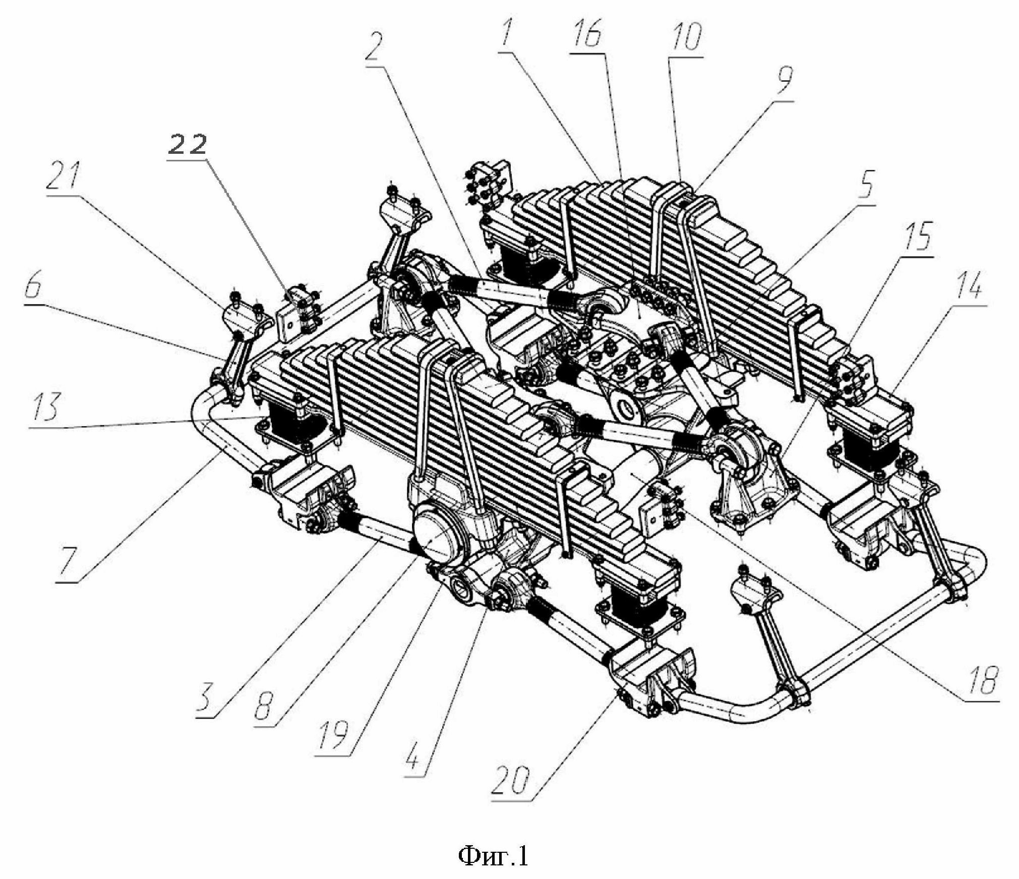
Description
Полезная модель относится к области транспортного машиностроения, а именно, к балансирным рессорным подвескам транспортных средств.The utility model relates to the field of transport engineering, namely, to balancing spring suspensions of vehicles.
Известна балансирная рессорная подвеска транспортного средства, содержащая две продольные листовые рессоры, верхние и нижние продольные реактивные штанги, правый и левый кронштейны с запрессованными осями балансиров и стабилизатор поперечной устойчивости с П-образной штангой и стойками. Листовые рессоры закреплены средней частью с помощью стремянок к башмаку. На верхних частях балок среднего и заднего мостов справа и слева установлены опоры рессор, закрепленные совместно с расположенными под ними рычагами с помощью болтов и гаек. На опорах рессор закреплены концы листовых рессор. Верхние реактивные штанги выполнены на концах с резинометаллическими шарнирами, и установлены одним концом на картере редуктора моста, а другим с помощью кронштейна - на поперечине рамы. В кронштейнах жестко закреплена поперечная стяжка, на концах которой через проставочные элементы закреплены двухопорные резинометаллические шарниры нижних реактивных штанг, связывающих кронштейны балансиров с балками мостов транспортного средства. (см. Задняя подвеска КАМАЗ-6520, https://www.konsulavto.ru/acat/trucks/kamaz/kamaz-6520/podveska-zadnjaja-v-sbore, дата обращения 08.08.2022г.).Known balancing spring suspension of the vehicle, containing two longitudinal leaf springs, upper and lower longitudinal jet rods, right and left brackets with pressed axles balancers and anti-roll bar with a U-shaped bar and uprights. The leaf springs are fixed in the middle part with the help of stepladders to the shoe. On the upper parts of the beams of the middle and rear axles, spring supports are installed on the right and left, fixed together with the levers located under them with the help of bolts and nuts. On the supports of the springs, the ends of the leaf springs are fixed. The upper jet rods are made at the ends with rubber-metal hinges, and are installed at one end on the crankcase of the axle reduction gear, and with the other end using a bracket - on the frame cross member. In the brackets, a transverse coupler is rigidly fixed, at the ends of which, through the spacer elements, two-support rubber-metal hinges of the lower torque rods are fixed, connecting the brackets of the balancers with the beams of the bridges of the vehicle. (see KAMAZ-6520 rear suspension, https://www.konsulavto.ru/acat/trucks/kamaz/kamaz-6520/podveska-zadnjaja-v-sbore, accessed 08.08.2022).
Известна балансирная рессорная подвеска транспортного средства, содержащая листовые рессоры, закрепленные средней частью с помощью стремянок к башмаку, а концами - на опорах мостов, верхние V-образные реактивные штанги, установленные одним концом на мосту, а другим с помощью кронштейна - на раме, нижние реактивные штанги, кронштейны с осями балансиров, ограничители хода, закрепленные к нижним полкам лонжеронов рамы над средним и задним мостами, стабилизатор поперечной устойчивости, состоящий из стоек и П-образной штанги, закрепленный отогнутыми концами через нижние рычаги с задним мостом, амортизаторы, закрепленные нижней частью к нижним рычагам, а верхней частью через кронштейн - к боковым стенкам лонжеронов рамы, стабилизатор поперечной устойчивости, закрепленный через нижние рычаги со средним мостом, при этом стойки стабилизаторов поперечной устойчивости соединены с боковой стенкой рамы, а нижние реактивные штанги закреплены через бобышки к кронштейну оси балансира (см. патент RU №200694, МПК B60G5/00, B60G11/02 (2006.01), опубл. 05.11.2020г.).Known balancing spring suspension of the vehicle, containing leaf springs, fixed in the middle part with the help of ladders to the shoe, and the ends - on the supports of the bridges, the upper V-shaped jet rods, installed at one end on the bridge, and the other with the help of a bracket - on the frame, the lower jet rods, brackets with balancer axles, travel stops attached to the lower shelves of the frame side members above the middle and rear axles, anti-roll bar, consisting of struts and a U-shaped rod, fixed with bent ends through the lower levers with the rear axle, shock absorbers fixed to the lower partly to the lower arms, and the upper part through the bracket - to the side walls of the frame side members, the anti-roll bar, fixed through the lower arms with the middle axle, while the anti-roll bars are connected to the side wall of the frame, and the lower jet rods are fixed through the bosses to the bracket balancer axles (see patent RU No. 2 00694, IPC B60G5/00, B60G11/02 (2006.01), publ. 11/05/2020).
Недостатком известных решений является отсутствие надежной фиксации концов рессор, что повышает риск их выскакивания за пределы мостов в случае максимального вывешивания (хода отбоя) мостов, кроме того не обеспечиваются прочностные показатели, что отрицательно сказывается на надежности конструкции.The disadvantage of the known solutions is the lack of reliable fixation of the ends of the springs, which increases the risk of them jumping out of the bridges in the event of maximum hanging (rebound stroke) of the bridges, in addition, strength indicators are not provided, which negatively affects the reliability of the structure.
Наиболее близкой к заявляемому техническому решению по совокупности существенных признаков является балансирная подвеска мостов транспортного средства, содержащая продольные листовые рессоры, закрепленные средней частью с помощью стремянок к башмаку, а концами установленные на опорах мостов, имеющие резинометаллические шарниры верхние реактивные штанги, установленные одним концом на картере редуктора моста, а другим с помощью кронштейна - на поперечине рамы, и нижние реактивные штанги, кронштейны с запрессованными осями балансиров, жестко закрепленную в кронштейнах поперечную стяжку, на концах которой через проставочные элементы закреплены двухопорные резинометаллические шарниры нижних реактивных штанг, связывающих кронштейны балансиров с балками мостов транспортного средства. Подвеска также содержит закрепленный на мосту стабилизатор поперечной устойчивости, состоящий из стоек и П-образной рамы, при этом концы листовых рессор установлены на опорах мостов через упругие элементы. Верхние реактивные штанги выполнены V-образными (см. патент RU №148755, МПК B60G5/00 (2006.01), опубл. 10.12.2014г.).Closest to the claimed technical solution in terms of the essential features is the balancing suspension of the bridges of the vehicle, containing longitudinal leaf springs, fixed in the middle part with the help of ladders to the shoe, and the ends mounted on the bridge supports, having rubber-metal hinges, the upper jet rods, mounted at one end on the crankcase of the axle reducer, and with the help of a bracket - on the frame cross member, and lower jet rods, brackets with pressed balancer axles, a transverse coupler rigidly fixed in the brackets, at the ends of which, through spacer elements, two-support rubber-metal hinges of the lower jet rods connecting the balancer brackets with beams are fixed vehicle bridges. The suspension also contains a stabilizer bar fixed on the bridge, consisting of struts and a U-shaped frame, while the ends of the leaf springs are mounted on the bridge supports through elastic elements. The upper jet rods are V-shaped (see patent RU No. 148755, IPC B60G5/00 (2006.01), publ. 10.12.2014).
Конструкция вышеописанной подвески имеет узлы, являющиеся менее долговечными и надежными. The design of the suspension described above has nodes that are less durable and reliable.
Задачей, на решение которой направлено заявляемое техническое решение, является повышение надежности при эксплуатации транспортного средства.The task to be solved by the claimed technical solution is to increase the reliability in the operation of the vehicle.
Для решения поставленной задачи балансирная рессорная подвеска транспортного средства, содержащая листовые рессоры, выполненные с возможностью крепления концами на опорах мостов и закрепленные средней частью с помощью стремянок к башмаку, закрепленному на кронштейнах с запрессованными осями балансиров, при этом кронштейны связаны между собой в нижних частях поперечной стяжкой, на торцах которой имеются кронштейны для крепления концов нижних реактивных штанг, стабилизатор поперечной устойчивости, состоящий из стоек и П-образной штанги и выполненный с возможностью крепления отогнутыми концами через нижние рычаги к заднему мосту, дополнительно содержит стабилизатор поперечной устойчивости, выполненный с возможностью крепления через нижние рычаги со средним мостом, в качестве шарнирных соединений П-образных штанг и стоек стабилизаторов использованы сайлентблоки, при этом нижняя часть стоек состоит из двух разъемных частей, кроме того концы рессор, лежащие на опорах мостов, зафиксированы пластинами.To solve the problem, a balancing spring suspension of a vehicle, containing leaf springs, made with the possibility of fastening the ends on the bridge supports and fixed by the middle part with the help of stepladders to the shoe, fixed on brackets with pressed axles of the balancers, while the brackets are connected to each other in the lower parts of the transverse coupler, at the ends of which there are brackets for attaching the ends of the lower torque rods, an anti-roll bar, consisting of struts and a U-shaped rod and made with the possibility of fastening with bent ends through the lower levers to the rear axle, additionally contains a stabilizer bar, made with the possibility of fastening through the lower levers with the middle axle, silent blocks are used as swivel joints of the U-shaped rods and stabilizer struts, while the lower part of the struts consists of two detachable parts, in addition, the ends of the springs lying on the axle supports are fixed plates.
Совокупность существенных признаков, заключающаяся в том, что подвеска дополнительно содержит стабилизатор поперечной устойчивости, выполненный с возможностью крепления через нижние рычаги со средним мостом, в качестве шарнирных соединений П-образных штанг и стоек стабилизаторов использованы сайлентблоки, при этом нижняя часть стоек состоит из двух разъемных частей, кроме того концы рессор, лежащие на опорах мостов, зафиксированы пластинами, позволяет обеспечить надежность конструкции при ее эксплуатации на транспортном средстве.The set of essential features, which consists in the fact that the suspension additionally contains an anti-roll bar, made with the possibility of fastening through the lower levers with the middle axle, silent blocks are used as swivel joints of the U-shaped rods and stabilizer struts, while the lower part of the struts consists of two detachable parts, in addition, the ends of the springs lying on the axle supports are fixed with plates, which makes it possible to ensure the reliability of the structure during its operation on a vehicle.
Заявляемое техническое решение поясняется чертежами:The proposed technical solution is illustrated by drawings:
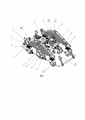
фиг. 1 – балансирная рессорная подвеска, вид сверху в изометрии;fig. 1 - balancing spring suspension, top view in isometry;
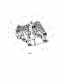
фиг. 2 – то же, вид снизу в изометрии;fig. 2 – the same, isometric view from below;
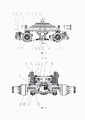
фиг. 3 –подвеска в сборе с рамой и мостами, вид слева;fig. 3 - suspension assembly with frame and bridges, left view;
фиг. 4 – разрез А-А на фиг.3.fig. 4 - section A-A in Fig.3.
Балансирная рессорная подвеска транспортного средства содержит листовые рессоры 1, верхние V-образные реактивные штанги 2 и нижние реактивные штанги 3, кронштейны 4 с запрессованными осями 5 балансиров, стабилизаторы поперечной устойчивости, состоящие из стоек 6 и П-образных штанг 7.Balance spring suspension of the vehicle contains
Рессоры 1 закреплены средней частью на башмаках 8 с помощью накладок 9 и стремянок 10. Башмаки 8 крепятся на кронштейнах 4 через оси 5 с помощью гаек. Справа и слева на среднем мосту 11 и заднем мосту 12 закреплены подушки 13, на которых зафиксированы концы рессор 1 с помощью пластин 14, благодаря чему исключается вероятность разъединения рессор 1 и мостов 11 и 12. Кроме того, данное решение позволяет ограничивать ход мостов 11 и 12 на отбой.The
Верхние V-образные реактивные штанги 2 установлены одними из концов на мостах 11 и 12 через рычаги 15, а другими концами с помощью кронштейнов 16 – на раме 17. На рычагах 15 выполнены усиливающие ребра жесткости, увеличивающие прочность деталей. Кронштейны 4, крепящиеся снизу к поперечине рамы 17, связаны между собой в нижних частях стяжкой 18, на торцах которых имеются кронштейны 19 для крепления концов нижних реактивных штанг 3. Другими концами штанги 3 крепятся к среднему 11 и заднему мосту 12.The upper V-
П-образные штанги 7 поперечной устойчивости автомобиля закреплены спереди моста 11 и сзади моста 12 через рычаги 20 и подвешены на стойках 6, крепящихся через кронштейны 21 к раме 17. В качестве шарнирных соединений П-образных штанг 7 и стоек 6 стабилизаторов использованы сайлентблоки, уменьшающие вибронагрузки, передающиеся от неровностей дорожной поверхности как на элементы системы стабилизации, так и, в свою очередь, на кузов автомобиля в целом. Сайлентблоки имеют более качественную виброгасящую способность и большую долговечность. На аналоге применены втулки и подушки из витура, долговечность, износостойкость и амортизационные свойства которых ниже. Кроме того, нижняя часть стоек 6 состоит из двух разъемных частей, что исключает необходимость долговременной запрессовки штанги 7 в проушину нижней части стойки 6 (как у аналога), тем самым повышая надежность конструкции и упрощая процесс сборки подвески. The U-shaped
С внешней стороны на боковых стенках лонжеронов рамы 17 установлены ограничители 22 хода сжатия рессор 1. Крепление ограничителей 22 на боковой стенке лонжерона является намного жёстче по сравнению с креплением на нижней полке лонжерона, как у аналога. Крепление на нижней полке лонжерона крайне нежелательно в связи с его прогибом (деформацией) при ударных нагрузках, воспринимаемых рамой от мостов. На заявляемой подвеске рессора 1 доходит до ограничителя 22 первее, чем мосты 11 и 12 могли бы дойти до рамы 17. Таким образом, исключается возможность такого нежелательного контакта.From the outside, on the side walls of the side members of the
Дополнительном преимуществом является применение стяжки 18 с изгибом в центральной части. Такая стяжка является универсальной и унифицированной, так как в случае расположения карданного вала ниже оси стяжки 18 не произойдет вредного контакта их друг с другом.An additional advantage is the use of screed 18 with a bend in the central part. Such a coupler is universal and unified, since if the cardan shaft is located below the axis of the
Заявляемое техническое решение позволяет повысить надежность конструкции при эксплуатации транспортного средства.The proposed technical solution allows to increase the reliability of the design during operation of the vehicle.
Заявляемое техническое решение возможно для реализации на стандартном технологическом оборудовании.The proposed technical solution is possible for implementation on standard process equipment.
Claims (1)
Publications (1)
| Publication Number | Publication Date |
|---|---|
| RU215263U1 true RU215263U1 (en) | 2022-12-06 |
Family
ID=
Cited By (1)
| Publication number | Priority date | Publication date | Assignee | Title |
|---|---|---|---|---|
| RU221785U1 (en) * | 2023-04-11 | 2023-11-23 | Общество С Ограниченной Ответственностью "Научно-Производственное Объединение "Ростар" | Vehicle rear suspension |
Citations (5)
| Publication number | Priority date | Publication date | Assignee | Title |
|---|---|---|---|---|
| US3964735A (en) * | 1975-03-03 | 1976-06-22 | Wright Oliver L | Torsion bar adaptor for vehicle springs |
| RU148755U1 (en) * | 2014-06-18 | 2014-12-10 | Открытое акционерное общество "КАМАЗ" | VEHICLE BALANCE SUSPENSION |
| WO2015121006A1 (en) * | 2014-02-17 | 2015-08-20 | Zf Friedrichshafen Ag | Chassis system for a motor vehicle |
| RU165639U1 (en) * | 2016-02-24 | 2016-10-27 | Публичное акционерное общество "КАМАЗ" | REAR SUSPENSION OF A VEHICLE BRIDGE |
| RU200694U1 (en) * | 2020-07-17 | 2020-11-05 | Публичное акционерное общество "КАМАЗ" | BALANCING SPRING SUSPENSION OF THE VEHICLE |
Patent Citations (5)
| Publication number | Priority date | Publication date | Assignee | Title |
|---|---|---|---|---|
| US3964735A (en) * | 1975-03-03 | 1976-06-22 | Wright Oliver L | Torsion bar adaptor for vehicle springs |
| WO2015121006A1 (en) * | 2014-02-17 | 2015-08-20 | Zf Friedrichshafen Ag | Chassis system for a motor vehicle |
| RU148755U1 (en) * | 2014-06-18 | 2014-12-10 | Открытое акционерное общество "КАМАЗ" | VEHICLE BALANCE SUSPENSION |
| RU165639U1 (en) * | 2016-02-24 | 2016-10-27 | Публичное акционерное общество "КАМАЗ" | REAR SUSPENSION OF A VEHICLE BRIDGE |
| RU200694U1 (en) * | 2020-07-17 | 2020-11-05 | Публичное акционерное общество "КАМАЗ" | BALANCING SPRING SUSPENSION OF THE VEHICLE |
Cited By (3)
| Publication number | Priority date | Publication date | Assignee | Title |
|---|---|---|---|---|
| RU221785U1 (en) * | 2023-04-11 | 2023-11-23 | Общество С Ограниченной Ответственностью "Научно-Производственное Объединение "Ростар" | Vehicle rear suspension |
| RU222323U1 (en) * | 2023-04-11 | 2023-12-20 | Общество с ограниченной ответственностью "Сибтрак" | Balance leaf spring suspension of a vehicle |
| RU238197U1 (en) * | 2025-01-20 | 2025-10-21 | Публичное акционерное общество "КАМАЗ" | Front axle suspension of a vehicle |
Similar Documents
| Publication | Publication Date | Title |
|---|---|---|
| JP6435417B2 (en) | Multiple support point independent suspension system | |
| RU165639U1 (en) | REAR SUSPENSION OF A VEHICLE BRIDGE | |
| RU215263U1 (en) | Balance spring suspension | |
| RU148755U1 (en) | VEHICLE BALANCE SUSPENSION | |
| US3154321A (en) | Air-ride truck suspension | |
| RU183693U1 (en) | DEPENDENT SPRING SUSPENSION OF A VEHICLE | |
| RU196741U1 (en) | BALANCED PNEUMATIC SUSPENSION OF A VEHICLE | |
| RU109437U1 (en) | SUSPENSION VEHICLE WITH STABILIZER | |
| RU222323U1 (en) | Balance leaf spring suspension of a vehicle | |
| US9186946B2 (en) | Vehicle suspension with X-linkage | |
| RU221785U1 (en) | Vehicle rear suspension | |
| CN205871667U (en) | Balanced axle suspension frame assembly | |
| RU219284U1 (en) | VEHICLE BALANCE SPRING SUSPENSION | |
| RU211672U1 (en) | Vehicle front suspension | |
| RU229465U1 (en) | Reinforced spring suspension of a vehicle | |
| RU154775U1 (en) | VERTICAL VIBRATION STABILIZER BRIDGE WHEELED VEHICLE | |
| CN117863792A (en) | A rubber suspension system for automatic container transport vehicles in ports | |
| CN201442502U (en) | Double rear axle air suspension | |
| RU200215U1 (en) | FRONT VEHICLE SUSPENSION | |
| US1971959A (en) | Equalizing and shock-absorbing means for vehicles | |
| RU221236U1 (en) | BALANCER SUSPENSION OF A VEHICLE | |
| RU181412U1 (en) | REAR PNEUMATIC SUSPENSION OF A VEHICLE | |
| RU238197U1 (en) | Front axle suspension of a vehicle | |
| RU233343U1 (en) | Combined front suspension of the vehicle | |
| RU241995U1 (en) | Trailing arm |