RU2148503C1 - Vehicle hydromechanical transmission with two or more ranges - Google Patents
Vehicle hydromechanical transmission with two or more ranges Download PDFInfo
- Publication number
- RU2148503C1 RU2148503C1 RU95111819A RU95111819A RU2148503C1 RU 2148503 C1 RU2148503 C1 RU 2148503C1 RU 95111819 A RU95111819 A RU 95111819A RU 95111819 A RU95111819 A RU 95111819A RU 2148503 C1 RU2148503 C1 RU 2148503C1
- Authority
- RU
- Russia
- Prior art keywords
- transmission
- planetary
- gear
- hydromechanical
- housing
- Prior art date
Links
Images
Landscapes
- Control Of Transmission Device (AREA)
- Motor Power Transmission Devices (AREA)
Abstract
Description
Изобретение относится к транспортному машиностроению и может быть использовано в качестве центральной или бортовой гидромеханической коробки передач с двумя и более диапазонами в трансмиссиях различных гусеничных и колесных машин. Из патентной и научно-технической литературы известны гидромеханические передачи с двумя и более диапазонами /1/, /2/, /3/. The invention relates to transport engineering and can be used as a central or onboard hydromechanical gearbox with two or more ranges in the transmissions of various tracked and wheeled vehicles. From the patent and scientific literature known hydromechanical transmission with two or more ranges / 1 /, / 2 /, / 3 /.
Известна гидромеханическая передача для трансмиссий транспортных средств, содержащая корпус, две гидравлически связанные между собой гидромашины, по меньшей мере одна из которых выполнена регулируемой, ведущий и ведомый валы, кинематически связанные с гидромашинами, планетарный дифференциал, входное звено которого связано с одной из гидромашин, а выходное - с ведомым валом через зубчатые передачи, и управляемые муфты /1/. Данная конструкция выбрана авторами за прототип. Known hydromechanical transmission for vehicle transmissions, comprising a housing, two hydraulically interconnected hydraulic machines, at least one of which is adjustable, drive and driven shafts kinematically connected to hydraulic machines, a planetary differential, the input link of which is connected to one of the hydraulic machines, and output - with a driven shaft through gears, and controlled couplings / 1 /. This design is selected by the authors for the prototype.
Недостатками известной гидромеханической передачи является несовершенство процесса перехода с одного режима на другой. Установка коробки передач параллельно гидрообъемной передаче и планетарному дифференциалу приводит к необходимости в момент переключения режимов (диапазонов) изменять угловую скорость гидромотора и связанной с ним солнечной шестерни планетарного дифференциала от максимального значения в конце предыдущего режима к минимальному в начале последующего, т.е. возврата гидромотора в исходное положение. Это приводит к повышению времени, затрачиваемого на переключение, т.е. снижение динамических свойств машины при разгоне. Последовательное размещение привода гидромотора, гидромашин, планетарного дифференциала, зубчатых передач с управляемыми муфтами, а также установка всех элементов в одном корпусе приводят к увеличению осевого габарита передачи и затруднению при размещении гидромеханической передачи в транспортных средствах, имеющих различную компановку. Переход на прямую (механическую) передачу изменяет способ регулирования скоростью: вместо регулирования гидравлической ветвью осуществляется регулирование двигателем. The disadvantages of the known hydromechanical transmission is the imperfection of the transition from one mode to another. Installing the gearbox parallel to the hydrostatic transmission and the planetary differential leads to the need at the time of switching modes (ranges) to change the angular speed of the hydraulic motor and the associated planetary differential sun gear from the maximum value at the end of the previous mode to the minimum at the beginning of the subsequent one, i.e. return of the hydraulic motor to its original position. This leads to an increase in the time spent on switching, i.e. decrease in dynamic properties of the car during acceleration. The sequential placement of the hydraulic motor drive, hydraulic machines, planetary differential, gears with controlled couplings, as well as the installation of all elements in one housing, increase the axial dimension of the gear and make it difficult to place the hydromechanical gear in vehicles with different layouts. Switching to direct (mechanical) transmission changes the way speed is controlled: instead of being regulated by a hydraulic branch, the engine is controlled.
Технической задачей изобретения является повышение качества процесса управления, улучшение компановочных свойств при использовании гидромеханической передачи в различных гусеничных и колесных транспортных средствах. An object of the invention is to improve the quality of the control process, improve line-up properties when using hydromechanical transmission in various tracked and wheeled vehicles.
Поставленная техническая задача решается тем, что в гидропередаче, содержащей корпус, две гидравлически связанные между собой гидромашины, по меньшей мере одна из которых является регулируемой, ведущий и ведомый валы, кинематически связанные с гидромашинами, планетарный дифференциал, коробку согласующих передач, связанную с ведущим валом, и управляемые зубчатые муфты, установлен дополнительно второй планетарный дифференциал, образующий с уже имеющимся планетарный четырехзвенник, соединенный через коробку согласующих передач с ведущим валом, а через водило одного и эпициклическую шестерню другого планетарных дифференциалов с ведомым валом, а также корпус выполнен их двух частей, одна из которых имеет возможность разворота. The stated technical problem is solved in that in a hydraulic transmission comprising a housing, two hydraulically interconnected hydraulic machines, at least one of which is adjustable, the drive and driven shafts kinematically connected to the hydraulic machines, a planetary differential, a matching gear box connected to the drive shaft , and controlled gear couplings, an additional second planetary differential is installed, forming with an existing planetary four-link connected through a gearbox of matching gears with a drive m shaft, and through the carrier and one epicyclic planetary gear other differentials to the driven shaft, and the housing is made of two parts, one of which has the ability to turn.
Такое конструкторское решение позволяет обеспечить кинематическое согласование переключения и сокращение времени на процесс переключения, снижение осевых габаритов передачи, улучшение компоновочных свойств при использовании гидромеханической передачи в различных гусеничных и колесных транспортных средствах за счет возможности относительного разворота разделенного на две части корпуса, которые связаны между собой при помощи фланцевого соединения. Such a design solution allows to provide kinematic coordination of the shift and reduce the time for the shift process, reduce the axial dimensions of the transmission, improve the layout properties when using hydromechanical transmission in various tracked and wheeled vehicles due to the possibility of a relative turn of the body divided into two parts, which are interconnected when help flange connection.
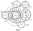
На фиг.1 показана схема гидромеханической передачи; на фиг.2 - предельные положения корпуса привода гидромотора при развороте его относительно корпуса передачи. Figure 1 shows a diagram of a hydromechanical transmission; figure 2 - limit position of the housing of the hydraulic motor drive when it is rotated relative to the transmission housing.
Гидромеханическая передача содержит два корпуса 1 и 2, ведущий 3 и ведомый 4 валы, две гидравлически связанные между собой гидромашины 5 и 6, одна из которых является регулируемой. В корпусе 1 размещены базовый механизм 7, коробка согласующих передач 8, шестерни 9, 10, 11 привода гидронасоса 5. Базовый механизм 7 включает два планетарных дифференциала 12 и 13. В корпусе 2 установлены шестерни 14, 15, 16 привода гидромотора 6. Корпус 2 устанавливается на корпусе 1 посредством цилиндрического фланцевого соединения 17 с центрирующим буртиком. Такое соединение позволяет разворачивать корпус 2 вокруг оси планетарных дифференциалов относительно корпуса 1. The hydromechanical transmission contains two
Коробка согласующих передач содержит шестерни 18, 19 зубчатой цилиндрической передачи второго диапазона, шестерни 20, 21 третьего диапазона и шестерни 22, 23 четвертого диапазона, зубчатую муфту 24 включения второго и четвертого диапазонов, зубчатую муфту 25 включения первого и третьего диапазонов, неподвижный зубчатый венец 26 первого диапазона и зубчатый венец 27 третьего диапазона. The matching gear box contains second gear spur gears 18, 19, third range gears 20, 21 and fourth range gears 22, 23, second and fourth range gear couplings 24, first and third range gear couplings 25, fixed gear ring 26 the first range and ring gear 27 of the third range.
В общем случае количество зубчатых передач равно числу двухпоточных диапазонов. In general, the number of gears is equal to the number of dual-flow ranges.
Ведомый вал 4 соединен с водилом 28 первого планетарного дифференциала 12 и эпициклической шестерней 29 второго планетарного дифференциала 13. Эпициклическая шестерня 30 первого планетарного дифференциала 12 соединяется согласующей передачей через шестерни 20, 21, зубчатую муфту 25 с зубчатым венцом 27 ведущего вала 3 на третьем диапазоне или с неподвижным зубчатым венцом 26 на первом диапазоне. The driven shaft 4 is connected to the carrier 28 of the first planetary differential 12 and the epicyclic gear 29 of the second planetary differential 13. The epicyclic gear 30 of the first planetary differential 12 is connected by a matching gear through gears 20, 21, the gear coupling 25 with the gear ring 27 of the
Водило 31 второго планетарного дифференциала 13 имеет зубчатую муфту 24, посредством которой сцепляется с шестерней 19 согласующей передачи второго диапазона и с шестерней 23 согласующей передачи четвертого диапазона. Шестерни 18 и 22 согласующих передач второго и четвертого диапазонов и зубчатый венец 27 установлены на ведущем валу 3. The carrier 31 of the second planetary differential 13 has a gear clutch 24 through which it engages with the second gear of the matching gear of the second range and with the gear of the matching gear of the fourth range. Gears 18 and 22 of matching gears of the second and fourth ranges and gear ring 27 are installed on the
Гидромеханическая передача работает следующим образом. Hydromechanical transmission operates as follows.
На первом диапазоне при соединении муфты 25 и зубчатого венца 26, закрепленного на корпусе 1, останавливается эпициклическая шестерня 30 первого планетарного дифференциала 12. Мощность от ведущего вала 3 передается через шестерни 9, 10 и 11 привода гидронасоса на гидронасос 5, гидромотор 6 через шестерни 14, 15 и 16 привода гидромотора на солнечную шестерню 32 первого планетарного дифференциала 12 и на водило 28, связанное с ведомым валом 4. Первый диапазон является полнопоточным и при реверсировании гидронасоса обеспечивается передача заднего хода. In the first range, when the coupling 25 and the ring gear 26 mounted on the
На остальных диапазонах гидромеханическая передача работает как двухпоточная. On the remaining ranges, the hydromechanical transmission operates as a two-line transmission.
На втором диапазоне соединяется муфта 24 с шестерней 19 и мощность от ведущего вала передается через шестерни 18 и 19 к водилу 31 второго планетарного дифференциала 13. Вторая ветвь двухпоточной передачи идет от ведущего вала 3 через шестерни 9, 10, 11 привода гидронасоса, гидронасос 5, гидромотор 6, шестерни 14, 15, 16 привода гидромотора к солнечной шестерне 33 второго планетарного дифференциала 13. На втором диапазоне при параметре регулирования гидронасоса в пределах от (-1) до О двухпоточная передача работает с циркуляцией мощности, а в пределах от О до 1 - с передачей мощности двумя потоками. Аналогично происходит передача мощности и на четвертом диапазоне, только в этом случае муфта 24 соединена с шестерней 23 согласующей передачи четвертого диапазона. In the second range, the coupling 24 is connected to the gear 19 and the power from the drive shaft is transmitted through gears 18 and 19 to the carrier 31 of the second planetary differential 13. The second branch of the dual-flow transmission goes from the
Третий диапазон включается при соединении муфты 25 и зубчатого венца 27. Мощность от ведущего вала 3 передается через зубчатый венец 27 и муфту 25 к шестерням 20, 21 согласующей передачи к эпициклической шестерне 30 первого планетарного дифференциала 12. Вторая ветвь двухпоточной передачи аналогична второй ветви второго и четвертого диапазонов. На третьем диапазоне при параметре регулирования гидронасоса в пределах от (-1) до 0 осуществляется передача мощности двумя потоками, а в пределах от 0 до 1 - с циркуляцией мощности. The third range is included when the coupling 25 and the ring gear 27 are connected. The power from the
Для соответствия гидромеханической передачи компановке транспортного средства конфигурация передачи в поперечной плоскости может быть изменена. Для этого отсоединяют стяжные болты цилиндрического фланцевого соединения 17 и разворачивают корпус 2 привода гидромотора относительно корпуса 1 передачи. На чертеже показаны предельные положения 2I, 2II, 2III корпуса 2 привода гидромотора относительно корпуса 1 передачи.To match the hydromechanical transmission with the vehicle lineup, the transverse configuration of the transmission can be changed. To do this, disconnect the coupling bolts of the cylindrical flange connection 17 and deploy the
Такое исполнение конструкции позволяет повысить качество процесса управления, улучшить компановочные свойства при использовании гидромеханической передачи в различных гусеничных и колесных транспортных средствах. This design allows to improve the quality of the control process, to improve the layout properties when using hydromechanical transmission in various tracked and wheeled vehicles.
Источники информации
1. А.c. СССР N 1272040 А1, кл. F 16 H 47/00.Sources of information
1. A.c. USSR N 1272040 A1, cl. F 16 H 47/00.
2. Заявка N 93035917, кл. F 16 H 47/04. 2. Application N 93035917, cl. F 16 H 47/04.
3. Объемные гидромеханические передачи: Расчет и конструирование. О.М. Бабаев, Л. Н. Игнатов, Е.С. Кисточкин и др. Под общ.ред. Е.С. Кисточкина. - Л.: Машиностроение. 1987. - 256 с. 3. Volumetric hydromechanical transmission: Calculation and design. O.M. Babaev, L.N. Ignatov, E.S. Kistochkin and others. Under the general ed. E.S. Kistochkina. - L .: Mechanical engineering. 1987 .-- 256 p.
Claims (1)
Priority Applications (1)
| Application Number | Priority Date | Filing Date | Title |
|---|---|---|---|
| RU95111819A RU2148503C1 (en) | 1995-07-11 | 1995-07-11 | Vehicle hydromechanical transmission with two or more ranges |
Applications Claiming Priority (1)
| Application Number | Priority Date | Filing Date | Title |
|---|---|---|---|
| RU95111819A RU2148503C1 (en) | 1995-07-11 | 1995-07-11 | Vehicle hydromechanical transmission with two or more ranges |
Publications (2)
| Publication Number | Publication Date |
|---|---|
| RU95111819A RU95111819A (en) | 1997-06-20 |
| RU2148503C1 true RU2148503C1 (en) | 2000-05-10 |
Family
ID=20169928
Family Applications (1)
| Application Number | Title | Priority Date | Filing Date |
|---|---|---|---|
| RU95111819A RU2148503C1 (en) | 1995-07-11 | 1995-07-11 | Vehicle hydromechanical transmission with two or more ranges |
Country Status (1)
| Country | Link |
|---|---|
| RU (1) | RU2148503C1 (en) |
Cited By (6)
| Publication number | Priority date | Publication date | Assignee | Title |
|---|---|---|---|---|
| RU2236356C2 (en) * | 2002-04-18 | 2004-09-20 | ОАО "Харьковский тракторный завод им. С. Орджоникидзе" | Vehicle gearshift and steering gear |
| RU2335414C1 (en) * | 2007-06-29 | 2008-10-10 | Государственное образовательное учреждение высшего профессионального образования Московский государственный технический университет "МАМИ" | Hydromechanical transmission |
| RU2350809C1 (en) * | 2007-07-09 | 2009-03-27 | Владимир Степанович Григорчук | Gear box with hydraulic booster of torque |
| RU2370695C2 (en) * | 2006-10-05 | 2009-10-20 | ГКН Вальтершайд Гетрибе ГмбХ | Drive for agricultural machine mounted implement |
| RU2444660C1 (en) * | 2010-12-15 | 2012-03-10 | Государственное образовательное учреждение высшего профессионального образования Московский государственный технический университет "МАМИ" | Hydro mechanical displacement transmission |
| RU2750342C1 (en) * | 2020-08-24 | 2021-06-28 | Василий Дмитриевич Кузьменко | Hydromechanical transmission of vehicle |
Citations (3)
| Publication number | Priority date | Publication date | Assignee | Title |
|---|---|---|---|---|
| EP0081696A1 (en) * | 1981-12-01 | 1983-06-22 | Friedrich Prof. Dr.-Ing. Jarchow | Hydrostatic-mechanical transmission with input split power |
| SU1272040A1 (en) * | 1984-12-24 | 1986-11-23 | Предприятие П/Я Р-6194 | Hydromechanical transmission |
| RU93035917A (en) * | 1993-07-12 | 1995-05-27 | Акционерное общество "Специальное конструкторское бюро машиностроения" | HYDROMECHANICAL TRANSMISSION |
Family Cites Families (1)
| Publication number | Priority date | Publication date | Assignee | Title |
|---|---|---|---|---|
| RU2096672C1 (en) * | 1993-07-12 | 1997-11-20 | Акционерное общество Специальное конструкторское бюро машиностроения | Hydromechanical transmission |
-
1995
- 1995-07-11 RU RU95111819A patent/RU2148503C1/en active
Patent Citations (3)
| Publication number | Priority date | Publication date | Assignee | Title |
|---|---|---|---|---|
| EP0081696A1 (en) * | 1981-12-01 | 1983-06-22 | Friedrich Prof. Dr.-Ing. Jarchow | Hydrostatic-mechanical transmission with input split power |
| SU1272040A1 (en) * | 1984-12-24 | 1986-11-23 | Предприятие П/Я Р-6194 | Hydromechanical transmission |
| RU93035917A (en) * | 1993-07-12 | 1995-05-27 | Акционерное общество "Специальное конструкторское бюро машиностроения" | HYDROMECHANICAL TRANSMISSION |
Cited By (6)
| Publication number | Priority date | Publication date | Assignee | Title |
|---|---|---|---|---|
| RU2236356C2 (en) * | 2002-04-18 | 2004-09-20 | ОАО "Харьковский тракторный завод им. С. Орджоникидзе" | Vehicle gearshift and steering gear |
| RU2370695C2 (en) * | 2006-10-05 | 2009-10-20 | ГКН Вальтершайд Гетрибе ГмбХ | Drive for agricultural machine mounted implement |
| RU2335414C1 (en) * | 2007-06-29 | 2008-10-10 | Государственное образовательное учреждение высшего профессионального образования Московский государственный технический университет "МАМИ" | Hydromechanical transmission |
| RU2350809C1 (en) * | 2007-07-09 | 2009-03-27 | Владимир Степанович Григорчук | Gear box with hydraulic booster of torque |
| RU2444660C1 (en) * | 2010-12-15 | 2012-03-10 | Государственное образовательное учреждение высшего профессионального образования Московский государственный технический университет "МАМИ" | Hydro mechanical displacement transmission |
| RU2750342C1 (en) * | 2020-08-24 | 2021-06-28 | Василий Дмитриевич Кузьменко | Hydromechanical transmission of vehicle |
Also Published As
| Publication number | Publication date |
|---|---|
| RU95111819A (en) | 1997-06-20 |
Similar Documents
| Publication | Publication Date | Title |
|---|---|---|
| US4164156A (en) | Full reversing hydromechanical steering transmission with multi-range synchronous shifting concentric gear train package | |
| SU961551A3 (en) | Vehicle transmission | |
| US4431073A (en) | Two speed final drive gear box | |
| US4404869A (en) | Power transmission unit for motor vehicles | |
| RU1830011C (en) | Engine unit | |
| EP0076591A1 (en) | A transverse gearbox for a vehicle with an in-line engine | |
| US5643129A (en) | Speed reduction gearset and torque split differential mechanism | |
| US6454031B2 (en) | Vehicle transmission apparatus | |
| US4528870A (en) | Transmission for vehicles, in particular for automobiles with front wheel drive | |
| US3583256A (en) | Transmission | |
| US2399201A (en) | Power transmitting mechanism | |
| EP0003397B1 (en) | Coaxial multi-range gear train for transmissions | |
| RU2136512C1 (en) | Final drive | |
| US4690015A (en) | Power transfer device for automotive vehicles | |
| RU2148503C1 (en) | Vehicle hydromechanical transmission with two or more ranges | |
| US5168956A (en) | Transfer device for four wheel drive motor vehicle | |
| US12202536B2 (en) | Steering system for vehicles and vehicles having same | |
| JP3808927B2 (en) | Hydraulic-mechanical torque distribution transmission | |
| US5271479A (en) | Transfer apparatus for a vehicle | |
| JPH0311925B2 (en) | ||
| EP1506912A1 (en) | Two speed planetary final drive | |
| GB2051977A (en) | Power Transmission Mechanism | |
| SU1375241A1 (en) | Vehicle gear box | |
| US4805713A (en) | Power transmitting system for a four-wheel drive vehicle | |
| SU1458255A1 (en) | Reversing reduction gear of self-propelled vehicle |