RU2139171C1 - Reamer - Google Patents
Reamer Download PDFInfo
- Publication number
- RU2139171C1 RU2139171C1 RU95102486A RU95102486A RU2139171C1 RU 2139171 C1 RU2139171 C1 RU 2139171C1 RU 95102486 A RU95102486 A RU 95102486A RU 95102486 A RU95102486 A RU 95102486A RU 2139171 C1 RU2139171 C1 RU 2139171C1
- Authority
- RU
- Russia
- Prior art keywords
- cutting edge
- zone
- rear surface
- cutting
- insert
- Prior art date
Links
Images

Classifications
-
- B—PERFORMING OPERATIONS; TRANSPORTING
- B23—MACHINE TOOLS; METAL-WORKING NOT OTHERWISE PROVIDED FOR
- B23D—PLANING; SLOTTING; SHEARING; BROACHING; SAWING; FILING; SCRAPING; LIKE OPERATIONS FOR WORKING METAL BY REMOVING MATERIAL, NOT OTHERWISE PROVIDED FOR
- B23D77/00—Reaming tools
- B23D77/02—Reamers with inserted cutting edges
-
- B—PERFORMING OPERATIONS; TRANSPORTING
- B23—MACHINE TOOLS; METAL-WORKING NOT OTHERWISE PROVIDED FOR
- B23B—TURNING; BORING
- B23B27/00—Tools for turning or boring machines; Tools of a similar kind in general; Accessories therefor
- B23B27/02—Cutting tools with straight main part and cutting edge at an angle
-
- B—PERFORMING OPERATIONS; TRANSPORTING
- B23—MACHINE TOOLS; METAL-WORKING NOT OTHERWISE PROVIDED FOR
- B23D—PLANING; SLOTTING; SHEARING; BROACHING; SAWING; FILING; SCRAPING; LIKE OPERATIONS FOR WORKING METAL BY REMOVING MATERIAL, NOT OTHERWISE PROVIDED FOR
- B23D2277/00—Reaming tools
- B23D2277/04—Cutting angles
-
- B—PERFORMING OPERATIONS; TRANSPORTING
- B23—MACHINE TOOLS; METAL-WORKING NOT OTHERWISE PROVIDED FOR
- B23D—PLANING; SLOTTING; SHEARING; BROACHING; SAWING; FILING; SCRAPING; LIKE OPERATIONS FOR WORKING METAL BY REMOVING MATERIAL, NOT OTHERWISE PROVIDED FOR
- B23D2277/00—Reaming tools
- B23D2277/20—Number of cutting edges
- B23D2277/201—One
-
- B—PERFORMING OPERATIONS; TRANSPORTING
- B23—MACHINE TOOLS; METAL-WORKING NOT OTHERWISE PROVIDED FOR
- B23D—PLANING; SLOTTING; SHEARING; BROACHING; SAWING; FILING; SCRAPING; LIKE OPERATIONS FOR WORKING METAL BY REMOVING MATERIAL, NOT OTHERWISE PROVIDED FOR
- B23D2277/00—Reaming tools
- B23D2277/46—Guiding pads
-
- B—PERFORMING OPERATIONS; TRANSPORTING
- B23—MACHINE TOOLS; METAL-WORKING NOT OTHERWISE PROVIDED FOR
- B23D—PLANING; SLOTTING; SHEARING; BROACHING; SAWING; FILING; SCRAPING; LIKE OPERATIONS FOR WORKING METAL BY REMOVING MATERIAL, NOT OTHERWISE PROVIDED FOR
- B23D2277/00—Reaming tools
- B23D2277/62—Margins, i.e. the area on the circumference of the tool immediately behind the axial cutting edge
-
- Y—GENERAL TAGGING OF NEW TECHNOLOGICAL DEVELOPMENTS; GENERAL TAGGING OF CROSS-SECTIONAL TECHNOLOGIES SPANNING OVER SEVERAL SECTIONS OF THE IPC; TECHNICAL SUBJECTS COVERED BY FORMER USPC CROSS-REFERENCE ART COLLECTIONS [XRACs] AND DIGESTS
- Y10—TECHNICAL SUBJECTS COVERED BY FORMER USPC
- Y10S—TECHNICAL SUBJECTS COVERED BY FORMER USPC CROSS-REFERENCE ART COLLECTIONS [XRACs] AND DIGESTS
- Y10S408/00—Cutting by use of rotating axially moving tool
- Y10S408/713—Tool having detachable cutting edge
-
- Y—GENERAL TAGGING OF NEW TECHNOLOGICAL DEVELOPMENTS; GENERAL TAGGING OF CROSS-SECTIONAL TECHNOLOGIES SPANNING OVER SEVERAL SECTIONS OF THE IPC; TECHNICAL SUBJECTS COVERED BY FORMER USPC CROSS-REFERENCE ART COLLECTIONS [XRACs] AND DIGESTS
- Y10—TECHNICAL SUBJECTS COVERED BY FORMER USPC
- Y10T—TECHNICAL SUBJECTS COVERED BY FORMER US CLASSIFICATION
- Y10T407/00—Cutters, for shaping
- Y10T407/23—Cutters, for shaping including tool having plural alternatively usable cutting edges
-
- Y—GENERAL TAGGING OF NEW TECHNOLOGICAL DEVELOPMENTS; GENERAL TAGGING OF CROSS-SECTIONAL TECHNOLOGIES SPANNING OVER SEVERAL SECTIONS OF THE IPC; TECHNICAL SUBJECTS COVERED BY FORMER USPC CROSS-REFERENCE ART COLLECTIONS [XRACs] AND DIGESTS
- Y10—TECHNICAL SUBJECTS COVERED BY FORMER USPC
- Y10T—TECHNICAL SUBJECTS COVERED BY FORMER US CLASSIFICATION
- Y10T408/00—Cutting by use of rotating axially moving tool
- Y10T408/55—Cutting by use of rotating axially moving tool with work-engaging structure other than Tool or tool-support
- Y10T408/557—Frictionally engaging sides of opening in work
- Y10T408/558—Opening coaxial with Tool
- Y10T408/5583—Engaging sides of opening being enlarged by Tool
- Y10T408/5586—Engaging surface subsequent to tool-action on that surface
-
- Y—GENERAL TAGGING OF NEW TECHNOLOGICAL DEVELOPMENTS; GENERAL TAGGING OF CROSS-SECTIONAL TECHNOLOGIES SPANNING OVER SEVERAL SECTIONS OF THE IPC; TECHNICAL SUBJECTS COVERED BY FORMER USPC CROSS-REFERENCE ART COLLECTIONS [XRACs] AND DIGESTS
- Y10—TECHNICAL SUBJECTS COVERED BY FORMER USPC
- Y10T—TECHNICAL SUBJECTS COVERED BY FORMER US CLASSIFICATION
- Y10T408/00—Cutting by use of rotating axially moving tool
- Y10T408/89—Tool or Tool with support
- Y10T408/909—Having peripherally spaced cutting edges
Landscapes
- Engineering & Computer Science (AREA)
- Mechanical Engineering (AREA)
- Milling, Broaching, Filing, Reaming, And Others (AREA)
- Crystals, And After-Treatments Of Crystals (AREA)
- Drilling Tools (AREA)
- Massaging Devices (AREA)
- Soundproofing, Sound Blocking, And Sound Damping (AREA)
- Glass Compositions (AREA)
- Organic Low-Molecular-Weight Compounds And Preparation Thereof (AREA)
Abstract
Description
Изобретение относится к развертке, содержащей, по меньшей мере, одну режущую пластину с двумя относящимися к ней направляющими пластинами согласно ограничительной части пункта 1 формулы изобретения. The invention relates to a reamer comprising at least one cutting insert with two related guide plates according to the preamble of
Развертки такого типа служат для чистовой обработки поверхности отверстий с целью получения очень точной геометрии отверстия при очень высоком качестве поверхности. Поэтому развертки такого типа снабжаются двумя направляющими планками, которые точно так же, как и режущая пластина, вставляются в канавки, выполненные по периметру режущей пластины. Взаимодействующие со стенкой отверстия главная и вспомогательная режущие кромки режущей пластины выступают с поверхности развертки немного более, чем поверхность направляющих планок. Это расположение служит для того, чтобы избежать высоких усилий прижима на поверхности направляющих планок таким образом, чтобы они не повредили стенку обрабатываемого отверстия, но, и с другой стороны, оптимально направили инструмент в отверстие. Reamers of this type serve to finish the surface of the holes in order to obtain very accurate hole geometry with very high surface quality. Therefore, this type of reamer is equipped with two guide strips, which, just like the cutting insert, are inserted into grooves made around the perimeter of the cutting insert. The main and auxiliary cutting edges of the insert interacting with the wall of the hole protrude slightly more from the surface of the reamer than the surface of the guide bars. This arrangement serves to avoid high pressing forces on the surface of the guide rails so that they do not damage the wall of the hole being machined, but, on the other hand, optimally guide the tool into the hole.
При обработке поверхностей отверстий является общеизвестным, что после первой установки режущей пластины в развертке, во время первоначальной обработки отверстий происходит так называемый начальный износ, который значительно выше, чем происходящий после этого износ. Поэтому, с одной стороны, необходимо отрегулировать величину, на которую режущая пластина выступает над поверхностью тела развертки через определенный период времени для того, чтобы компенсировать начальный износ и получить желаемый размер отверстия. When processing the surface of the holes, it is well known that after the first installation of the cutting insert in the reamer, during the initial processing of the holes, the so-called initial wear occurs, which is significantly higher than the wear that occurs after this. Therefore, on the one hand, it is necessary to adjust the amount by which the cutting insert protrudes above the surface of the reamer body after a certain period of time in order to compensate for the initial wear and obtain the desired hole size.
Во время первой обработки отверстия режущая пластина выступает за поверхность направляющих планок более, чем это имеет место после начального износа. Из-за этого происходит сравнительно неточное направление развертки внутри обрабатываемого отверстия, вследствие чего геометрические свойства, например округлость, а также качество поверхности обрабатываемого отверстия, не отвечают поставленным требованиям. Во время более высокого начального износа не выполняются особенно высокие требования относительно геометрии и качества поверхности отверстия, поэтому приходится часто осуществлять подналадку для компенсации начального износа, что приводит к очень неэкономичному рабочему процессу. During the first machining of the hole, the cutting insert protrudes beyond the surface of the guide bars more than occurs after initial wear. Because of this, a relatively inaccurate sweep direction occurs inside the machined hole, as a result of which the geometric properties, such as roundness, as well as the surface quality of the machined hole, do not meet the stated requirements. During higher initial wear, especially high requirements regarding the geometry and surface quality of the hole are not met, therefore, it is often necessary to carry out adjustments to compensate for the initial wear, which leads to a very uneconomical workflow.
Известна развертка, содержащая по меньшей мере одну режущую пластину и две относящиеся к ней направляющие планки, причем режущая пластина имеет по меньшей мере одну главную режущую кромку и примыкающую к ней вспомогательную режущую кромку, при этом в зоне главной и вспомогательной режущих кромок расположена задняя поверхность, имеющая в области вспомогательной режущей кромки первую зону с задним углом около 7o (заявка Германии 4102716, B 23 D 77/02, 1991).Known reamer containing at least one cutting insert and two related guide strips, and the cutting plate has at least one main cutting edge and adjacent auxiliary cutting edge, while in the area of the main and auxiliary cutting edges is located the rear surface, having in the region of the auxiliary cutting edge a first zone with a trailing angle of about 7 ° (German application 4102716, B 23 D 77/02, 1991).
Задачей изобретения является создание развертки, в которой исключены вышеуказанные недостатки, и в особенности, начальный износ практически не больше, чем износ, возникающий в дальнейшем. The objective of the invention is to create a scan in which the above disadvantages are eliminated, and in particular, the initial wear is practically no more than wear that occurs in the future.
Эта задача решается в развертке указанного типа за счет того, что в области вспомогательной режущей кромки выполнена вторая дополнительная зона задней поверхности, примыкающая непосредственно к вспомогательной режущей кромке, переходящая в первую зону задней поверхности и имеющая задний угол значительно меньше заднего угла первой зоны задней поверхности. This problem is solved in a reamer of the indicated type due to the fact that in the region of the auxiliary cutting edge, a second additional zone of the rear surface is made adjacent directly to the auxiliary cutting edge, passing into the first zone of the rear surface and having a rear angle much smaller than the rear corner of the first zone of the rear surface.
При этом является целесообразным, чтобы задний угол второй дополнительной зоны задней поверхности составлял от 0,5o до 1,5o, предпочтительно около 1o; ширина второй дополнительной зоны задней поверхности, измеренная поперечно вспомогательной режущей кромке, составляла около от 0,06 до 0,1 мм, предпочтительно 0,08 мм; при этом желательно предусмотреть третью зону задней поверхности, примыкающую к первой зоне задней поверхности и имеющую задний угол, больший, чем угол первой зоны задней поверхности, и составляющий, приблизительно, 15o; кроме того, режущая пластина может быть выполнена, в основном, прямоугольной формы, а вспомогательная режущая кромка расположена вдоль ее продольной стороны; причем режущая пластина выполнена в виде поворотной пластины и имеет на диагонально противолежащих углах главную режущую кромку, переходящую в соответствующую вспомогательную режущую кромку; режущая пластина выполнена в виде многоугольника, предпочтительно с шестью углами, причем каждый угол служит в качестве главной режущей кромки, к которой примыкает вспомогательная режущая кромка.It is advisable that the rear corner of the second additional zone of the rear surface is from 0.5 o to 1.5 o , preferably about 1 o ; the width of the second additional zone of the rear surface, measured transverse to the auxiliary cutting edge, was from about 0.06 to 0.1 mm, preferably 0.08 mm; it is desirable to provide a third zone of the rear surface adjacent to the first zone of the rear surface and having a rear angle greater than the angle of the first zone of the rear surface, and amounting to approximately 15 o ; in addition, the cutting insert can be made mainly of a rectangular shape, and the auxiliary cutting edge is located along its longitudinal side; moreover, the cutting insert is made in the form of a rotary insert and has on the diagonally opposite angles the main cutting edge, which passes into the corresponding auxiliary cutting edge; the cutting insert is made in the form of a polygon, preferably with six angles, each corner serving as a main cutting edge adjacent to the auxiliary cutting edge.
За счет того что предусмотрена дополнительная область задней поверхности, примыкающая непосредственно к вспомогательной режущей кромке и имеющая очень плоский задний угол, в области вспомогательной режущей кромки режущей пластины имеется дополнительная направляющая поверхность, вследствие чего развертка может опираться снаружи на направляющие планки, в том числе и при обработке поверхности отверстия. Это приводит к очень спокойному и равномерному ходу инструмента в отверстии, благодаря чему износ режущей пластины во время обработки отверстий является очень равномерным. Таким образом, можно практически полностью исключить достаточно высокий начальный износ в особенности во время первой обработки отверстий по сравнению с известными инструментами. Поэтому после первого использования развертки нет необходимости в подналадочных работах, что имеет место у соответствующих инструментов. Due to the fact that there is an additional area of the rear surface adjacent directly to the auxiliary cutting edge and having a very flat trailing angle, there is an additional guide surface in the area of the auxiliary cutting edge of the cutting insert, as a result of which the reamer can rely on the guide rails from the outside, including surface treatment of the hole. This leads to a very calm and uniform tool travel in the hole, due to which the wear of the insert during hole processing is very uniform. Thus, it is possible to almost completely eliminate a sufficiently high initial wear, especially during the first machining of the holes in comparison with the known tools. Therefore, after the first use of the reamer, there is no need for adjustment work, which is the case with the corresponding tools.
Особенно предпочтительным является пример выполнения развертки, в котором задний угол дополнительной зоны задней поверхности составляет, приблизительно, 1o. Это означает, что от вспомогательной режущей кромки отходит задняя поверхность под углом 1o, если смотреть противоположно направлению вращения инструмента. Этот плоский уклон задней поверхности приводит к тому, что она при обработке отверстия служит в качестве направляющей поверхности для режущей пластины и, вместе с тем, для всего инструмента.Particularly preferred is a scan example in which the rear angle of the additional area of the rear surface is approximately 1 o . This means that the rear surface departs from the auxiliary cutting edge at an angle of 1 o when viewed opposite to the direction of rotation of the tool. This flat slope of the rear surface leads to the fact that during the machining of the hole, it serves as a guide surface for the cutting insert and, at the same time, for the entire tool.
Кроме того, предпочтительным является пример выполнения развертки, которая отличается тем, что ширина дополнительной зоны задней поверхности, проходящая поперечно к прохождению вспомогательной режущей кромки, составляет, предпочтительно, 8/100 мм. Таким образом, гарантируется, что за счет дополнительной зоны задней поверхности не возникает слишком больших усилий прижима к поверхности обрабатываемого отверстия. In addition, a sweep embodiment is preferable, characterized in that the width of the additional area of the rear surface extending transversely to the passage of the minor cutting edge is preferably 8/100 mm. Thus, it is guaranteed that due to the additional zone of the rear surface, there is not too much pressing force to the surface of the hole being machined.
Предпочтительным, кроме того, является пример выполнения развертки, режущая пластина у которой выполнена в виде поворотной пластины. Это выполнение позволяет извлечь ее при износе из инструмента и, после поворота на 180o, снова вставить в инструмент, причем прежние противолежащие главной и вспомогательной режущие кромки теперь могут служить в качестве новых главной и вспомогательной режущих кромок.Preferred, in addition, is an example of a scan, the cutting insert in which is made in the form of a rotary insert. This embodiment allows you to remove it during wear from the tool and, after turning through 180 o , reinsert it into the tool, and the old opposite main and auxiliary cutting edges can now serve as new main and auxiliary cutting edges.
И, наконец, является предпочтительной форма выполнения развертки, в которой режущая пластина выполнена в виде шестигранника. Здесь получается шесть главных и вспомогательных режущих кромок, благодаря чему сравнительно дорогой материал режущей пластины может быть использован многократно. And finally, a preferred embodiment of the development in which the cutting insert is made in the form of a hexagon. Here, six main and auxiliary cutting edges are obtained, due to which the relatively expensive material of the cutting insert can be used repeatedly.
Другие формы выполнения отражены в подпунктах. Other forms of implementation are reflected in subparagraphs.
Ниже изобретение поясняется более подробно с помощью чертежей, на которых показано:
на фиг. 1 - вид сверху на переднюю сторону режущей пластины в первой форме выполнения;
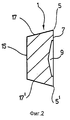
фиг. 2 - поперечное сечение режущей пластины, показанной по линии II-II на фиг. 1;
фиг. 3 - сильно увеличенное частичное изображение режущей кромки режущей пластины, показанной на фиг. 1 и 2;
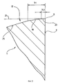
фиг. 4 - схематично изображенный вид сверху на переднюю сторону режущей пластины, в еще одном примере выполнения;
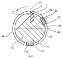
фиг. 5 - вид на переднюю сторону однолезвийной развертки;
фиг. 6 - представлена диаграмма, на которой показан размер обрабатываемого отверстия, полученный на длине резания режущей пластиной согласно фиг. 1;
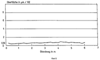
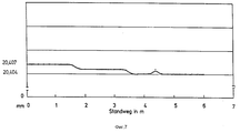
фиг. 7 - диаграмма, из которой видна поверхность отверстия, полученного разверткой согласно изобретению на пути резания, измеренном в метрах;
фиг. 8 - диаграмма, на которой показан размер отверстия, полученный обычной разверткой на длине резания инструмента.Below the invention is explained in more detail using the drawings, which show:
in FIG. 1 is a plan view of a front side of a cutting insert in a first embodiment;
FIG. 2 is a cross-sectional view of the insert shown along line II-II of FIG. 1;
FIG. 3 is a greatly enlarged partial image of the cutting edge of the insert shown in FIG. 1 and 2;
FIG. 4 is a schematic top view of a front side of a cutting insert, in yet another embodiment;
FIG. 5 is a view of the front side of a single-blade reamer;
FIG. 6 is a diagram showing the size of the machined hole obtained on the cutting length of the cutting insert according to FIG. 1;
FIG. 7 is a diagram from which the surface of a hole obtained by reaming according to the invention on a cutting path measured in meters is visible;
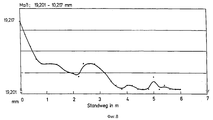
FIG. 8 is a diagram showing the size of a hole obtained by conventional sweep over the cutting length of a tool.
На фиг. 1 показана имеющая в основном прямоугольную форму режущая пластина 1 в виде сверху, причем здесь можно увидеть переднюю сторону или режущую часть 7. Правая верхняя кромка режущей пластины 1 скошена. Здесь получается главная режущая кромка 3, к которой примыкает вспомогательная режущая кромка 5, проходящая вдоль продольной кромки режущей пластины 1. При обработке отверстия режущая пластина 1 закреплена в развертке таким образом, что главная режущая кромка 3 первой входит в обрабатываемое отверстие и снимает материал со стенки отверстия. Затем чистовая обработка поверхности отверстия осуществляется в зоне вспомогательной режущей кромки 5. При обработке отверстия с помощью представленной здесь режущей пластины 1 снимается стружка толщиной около 1,5/10 мм. In FIG. 1 shows a generally rectangular-shaped cutting insert 1 in a plan view, where the front side or cutting
Режущая пластина 1 выполнена здесь в виде поворотной пластины. Это означает, что диагонально напротив главной режущей кромки 3 находится еще одна главная режущая кромка 3', к которой примыкает соответствующая вспомогательная режущая кромка 5'. Если главная и вспомогательная режущие кромки 3 и 5 износились, режущую пластину 1 можно повернуть в развертке на угол 180o, после чего можно применять не использованную до этого главную и вспомогательную режущую кромки 3' и 5'.The
На передней стороне 7 режущей пластины выполнена зажимная канавка 9, имеющая в основном V-образную форму. Самый глубокий участок V-образной зажимной канавки 9 обозначен линией 11. В зажимную канавку 9 известным образом входит захватка, с помощью которой режущая пластина 1 удерживается в пазу, выполненном по периметру развертки. On the
Для наглядности на фиг. 1 не показано, что вдоль продольных кромок 13 и 13', на передней стороне 7 могут находиться направляющие стружку поверхности, служащие для воздействия на стружку, снимаемую со стенки отверстия. For clarity, in FIG. 1, it is not shown that along the longitudinal edges 13 and 13 ', on the
На фиг. 2 в очень схематическом изображении показан вид с торца режущей пластины 1, где видна конструкция ее основания. Существенным является то, что ширина передней стороны 7 больше, чем ширина задней стороны 15 режущей пластины 1. Примыкающие к вспомогательной режущей кромке 5 или 5' поверхности называются задними поверхностями 17 и 17'. На чертеже видно, что поперечное сечение режущей пластины 1 имеет, в основном, трапециевидную форму. In FIG. 2, in a very schematic representation, an end view of the
На фиг. 2 штриховой линией определена зажимная канавка 9. In FIG. 2, a dashed line defines a
На фиг. 3 показано сильно увеличенное поперечное сечение режущей пластины 1 в зоне вспомогательной режущей кромки 5. Благодаря увеличению видно, что задняя поверхность 17 имеет несколько зон:
отчетливо видна первая зона 19 задней поверхности, проходящая - если смотреть от вспомогательной режущей кромки 5 - влево, под углом, приблизительно, 7o относительно воображаемой горизонтальной линии 21. Первая зона 19 задней поверхности не доходит до вспомогательной режущей кромки 5. Здесь, в непосредственном примыкании к вспомогательной режущей кромке 5, предусмотрена вторая дополнительная зона 23 задней поверхности, угол наклона которой, называемый задним углом, значительно меньше, чем у первой зоны 19 задней поверхности. Задний угол дополнительной зоны 23 задней поверхности составляет, предпочтительно, 1o. Он может составлять от 0,5o до 1,5o.In FIG. 3 shows a greatly enlarged cross section of the
the
К первой зоне 19 задней поверхности примыкает третья зона 25 задней поверхности, расположенная под большим задним углом по сравнению с первой зоной 19 задней поверхности, например, 15o относительно изображаемой горизонтальной линии 21.Adjacent to the
В изображении, показанном на фиг. 3, видно, что вспомогательная режущая кромка 5 соответствует линии пересечения двух плоскостей, первая из которых совпадает с передней стороной 7, а вторая плоскость - с дополнительной зоной 23 задней поверхности. In the image shown in FIG. 3, it is seen that the
Замеренная от вспомогательной режущей кромки 5 ширина b2 второй дополнительной зоны 23 задней поверхности составляет, предпочтительно, 8/100 мм. Она может находиться в диапазоне от, приблизительно, 6/100 мм до, максимально, 1/10 мм. The width b2, measured from the
Замеренная от вспомогательной режущей кромки 5 общая ширины b1 первой зоны задней поверхности составляет, например, 0,8-1 мм, причем этот размер включает ширину b2. Третья зона 25 задней поверхности продолжается непрерывно до задней стороны режущей пластины 1. The total width b1 of the first zone of the rear surface, measured from the
На фиг. 4 очень схематически показан вид сверху на переднюю сторону режущей пластины 10, выполненной в виде многоугольника, в данном случае - шестиугольника. Здесь также в области угла предусмотрена главная режущая кромка 30 и примыкающая к ней вспомогательная режущая кромка 50, таким образом, в представленной здесь режущей пластине имеется всего шесть главных режущих и шесть вспомогательных режущих кромок. На передней стороне 7 режущей пластины 10 могут быть выполнены зажимные канавки, служащие для закрепления режущей пластины 10 в соответствующем пазу, выполненном в теле развертки. In FIG. 4 very schematically shows a top view of the front side of the cutting
Зоны задней поверхности, предусмотренные в области вспомогательной режущей кромки 50, выполнены так же, как и в режущей пластине 1, что можно видеть на увеличенном изображении поперечного сечения на фиг. 3. Это означает, что со вспомогательной режущей кромкой 50 граничит дополнительная зона 23 задней поверхности, имеющая задний угол, равный 1o. К ней примыкает первая зона 19 задней поверхности с задним углом, равным 7o. И в заключение она переходит в третью зону 25 задней поверхности с задним углом 15o.The areas of the rear surface provided in the area of the
На фиг. 5 схематически показан вид сверху на торцевую сторону развертки 31, в окружной стенке 33 которой расположена первая канавка 35 для приема режущей пластины 1, вторая канавка 37 - для приема первой направляющей планки 39 и третья канавка 41 - для приема второй направляющей планки 43. Воображаемая средняя линия 45 первой направляющей планки 39 образует с воображаемым перпендикуляром 47, проходящим через вспомогательную режущую кромку 5 режущей пластины 1, угол около 40o. Вторая направляющая планка 43 расположена диаметрально противоположно режущей пластине 1.In FIG. 5 schematically shows a top view of the end side of the
Направление вращения развертки 31 при обработке отверстия показано стрелкой на фиг. 5. При этом вращении главная и вспомогательная режущие кромки 3 и 5 режущей пластины 1 снимают стружку со стенки отверстия. The direction of rotation of the
При вращении развертки 31 наружная кромка режущей пластины 1 описывает так называемую круговую траекторию 49, диаметр которой больше, чем окружность, описываемая наружными поверхностями направляющих планок 39 и 43. Это означает, что режущая пластина 1 выступает на окружность стенки 33 развертки 31 - если смотреть в радиальном направлении - дальше, чем поверхность направляющих планок 39 и 43. When the
При обработке отверстия к главной режущей кромке 3 и вспомогательной режущей кромке 5 режущей пластины 1 подводятся усилия, действующие на развертку 31 и вызывающие движения опрокидывания, под действием которых опережающая кромка 51 первой направляющей планки 39 и отстающая кромка 53 второй направляющей планки 43 контактируют со стенкой отверстия. При этом следует исходить из того, что кромки 51 и 53 выполнены каждая закругленными, благодаря чему при опирании развертки 31 не происходит повреждений поверхности отверстия, подлежащей обработке. При движении опрокидывания развертки 31 передняя поверхность 7 отклоняется от вертикальной линии 47, вследствие чего задняя поверхность 17 приближается к стенке обрабатываемого отверстия. Можно видеть, что задняя поверхность 17 служит для того, чтобы исключить контакт со стенкой отверстия и, тем самым, повреждение стенки обрабатываемого отверстия. When processing the hole to the
Дополнительная зона 23 задней поверхности режущей пластины 1 служит в качестве опорной поверхности и, тем самым, в качестве дополнительного направления развертки 31 в обрабатываемом отверстии. Развертка 31 прилегает, таким образом, с одной стороны, дополнительной зоной 23 задней поверхности, а с другой стороны, первой направляющей планкой 39 и, наконец, второй направляющей планкой 43 - к стенке отверстия. The
За счет особого выполнения задней поверхности 17 получается точно определяемая опорная поверхность в зоне режущей пластины 1. То же самое происходит, прежде всего, тогда, когда режущая пластина выполнена шестиугольной, то есть в форме, представленной на фиг. 4. Due to the special design of the
Благодаря особому выполнению режущей пластины, развертка 31 получает оптимальное направление в обрабатываемом отверстии, что позволяет получить высокую точность геометрии отверстия и особенно высокое качество поверхности. Thanks to the special design of the insert, the
Инструмент движется в обрабатываемом отверстии очень спокойно, вследствие чего до минимума снижается также начальный износ. При регулировании выхода работающей режущей кромки за пределы направляющих планок нет необходимости учитывать обычный начальный износ. Если она выступает незначительно, снижается вышеупомянутое движение опрокидывания развертки 31 в отверстии, благодаря чему дополнительно улучшается геометрия отверстия и качество его поверхности. The tool moves very quietly in the hole to be machined, which also minimizes initial wear. When regulating the exit of a working cutting edge beyond the limits of the guide bars, there is no need to take into account the usual initial wear. If it protrudes slightly, the aforementioned tipping motion of the
За счет особого выполнения задней поверхности режущей пластины 1 удается, прежде всего, избежать начального износа, превышающего обычный износ режущей пластины 1, вследствие чего можно дополнительно отметить, что кроме вышеуказанных преимуществ отпадает необходимость в подналадочных работах с разверткой 31 во время обработки. Здесь следует отметить, что режущая пластина 1 таким образом закреплена в теле развертки 31, что может регулироваться наружный диаметр развертки 31, задаваемый работающей режущей кромкой и противолежащей направляющей планкой 43. Due to the special implementation of the rear surface of the cutting
Для пояснения упомянутых здесь преимуществ развертки 31 здесь следует сослаться на фиг. 6, где воспроизведена диаграмма, на которой представлена шероховатость Rz по замеренному в метрах пути резания. Здесь можно видеть, что качество поверхности остается практически постоянным на пути резания, равном 6 м. В особенности видно, что после первого применения развертки 31, то есть после достижения пути резания, от приблизительно 1 м до 6 м, практически не происходит изменений шероховатости. To illustrate the advantages of the
То же самое получается при рассмотрении диаметра отверстия, получаемого разверткой 31, что более подробно поясняется на фиг. 7. На диаграмме, приведенной на этой фигуре, показан диаметр отверстия на пути резания, измеренном в метрах. На диаграмме видно, что диаметр отверстия во время всего пути резания снижается в процессе применения инструмента от заданного здесь в качестве промера значения 20,407 мм до 20,404 мм, причем, в частности, во время первого использования инструмента практически не происходит начального износа. На фиг. 8, например, представлено, что размер отверстия, получаемый обычной разверткой во время пути резания, равном 6 м, сильно уменьшается. При этом особенно отчетливо виден начальный износ, происходящий до достижения пути резания, равного 1 м, который делает обязательной подналадку наружного радиуса инструмента. The same is obtained when considering the diameter of the hole obtained by the
Сравнение фиг. 7 и 8 показывает особенно отчетливо, что за счет выполнения задней поверхности режущей пластины практически полностью исключается начальный износ. Износ режущей пластины остается, в основном, постоянным на всем ее пути резания. Comparison of FIG. 7 and 8 shows particularly clearly that due to the execution of the rear surface of the cutting insert, initial wear is almost completely eliminated. The wear of the insert remains essentially constant over its entire cutting path.
Из всего сказанного ясно, что развертка может быть оснащена также несколькими - расположенным друг за другом, если смотреть вдоль продольной оси развертки - режущими пластинами. К этим нескольким режущим пластинам могут относиться две направляющие планки, как это пояснено на примере фиг. 5. From the foregoing, it is clear that the reamer can also be equipped with several - located one after the other, when viewed along the longitudinal axis of the reamer - with cutting inserts. These several inserts may include two guide strips, as explained in the example of FIG. 5.
И, наконец, является также возможным выполнение развертки в виде ступенчатой развертки, причем предусмотрено несколько режущих пластин, служащих для обработки ступенчатого отверстия, причем все они выполнены в соответствии с представленным описанием. And finally, it is also possible to perform a sweep in the form of a stepped sweep, moreover, several cutting inserts are provided for processing a stepped hole, all of which are made in accordance with the description.
Во всех случаях проявляется одинаковый феномен: начальный износ режущих пластин, особенно ярко выраженный у обычных инструментов во время резания до 1 м, практически не отличается от износа, получаемого на пути резания от 1 до 6 м. Во всех случаях по-особому выполняется задняя поверхность, в частности ее дополнительная зона, отличающаяся очень малым задним углом, служащая в качестве направляющей поверхности, что обеспечивает оптимальную стабилизацию инструмента в обрабатываемом отверстии. За счет исключения особенно большого начального износа работающая режущая кромка режущей пластины может минимально выступать за направляющие планки, благодаря чему во всех случаях сильно снижается описываемый эффект опрокидывания, благодаря чему геометрия и качество поверхности обрабатываемого отверстия отвечают самым высоким требованиям. In all cases, the same phenomenon is manifested: the initial wear of the cutting inserts, which is especially pronounced in conventional tools during cutting up to 1 m, practically does not differ from the wear obtained on the cutting path from 1 to 6 m. In all cases, the back surface is performed in a special way , in particular, its additional zone, characterized by a very small rear angle, serving as a guide surface, which ensures optimal stabilization of the tool in the machined hole. Due to the exclusion of particularly large initial wear, the working cutting edge of the insert can minimally protrude beyond the guide bars, which in all cases greatly reduces the described tipping effect, due to which the geometry and surface quality of the machined hole meet the highest requirements.
Claims (7)
Applications Claiming Priority (2)
| Application Number | Priority Date | Filing Date | Title |
|---|---|---|---|
| DE4405749A DE4405749C2 (en) | 1994-02-23 | 1994-02-23 | Knife plate for a reamer |
| DEP4405749.0 | 1994-02-23 |
Publications (2)
| Publication Number | Publication Date |
|---|---|
| RU95102486A RU95102486A (en) | 1996-11-20 |
| RU2139171C1 true RU2139171C1 (en) | 1999-10-10 |
Family
ID=6510946
Family Applications (1)
| Application Number | Title | Priority Date | Filing Date |
|---|---|---|---|
| RU95102486A RU2139171C1 (en) | 1994-02-23 | 1995-02-22 | Reamer |
Country Status (15)
| Country | Link |
|---|---|
| US (1) | US5478179A (en) |
| EP (1) | EP0673700B1 (en) |
| JP (1) | JP3919241B2 (en) |
| KR (1) | KR100362551B1 (en) |
| AT (1) | ATE158210T1 (en) |
| BR (1) | BR9500684A (en) |
| CA (1) | CA2142148C (en) |
| CZ (1) | CZ285026B6 (en) |
| DE (2) | DE4405749C2 (en) |
| DK (1) | DK0673700T3 (en) |
| ES (1) | ES2109020T3 (en) |
| HU (1) | HU217935B (en) |
| RU (1) | RU2139171C1 (en) |
| SK (1) | SK24095A3 (en) |
| TW (1) | TW334371B (en) |
Families Citing this family (18)
| Publication number | Priority date | Publication date | Assignee | Title |
|---|---|---|---|---|
| DE19518241C2 (en) * | 1995-05-15 | 1998-07-16 | Mapal Fab Praezision | Reamer |
| US5823720A (en) * | 1996-02-16 | 1998-10-20 | Bitmoore | High precision cutting tools |
| US5758997A (en) * | 1996-08-07 | 1998-06-02 | Mealey; Michael | Self-centering indexable drill |
| SE519728C2 (en) * | 1998-08-13 | 2003-04-01 | Sandvik Ab | Spiral drill and polygonal indexable cutter with release surfaces with different angles |
| US6547495B2 (en) | 2001-01-29 | 2003-04-15 | General Electric Company | Method for reaming hole and improved reamer |
| US20030156912A1 (en) * | 2002-01-22 | 2003-08-21 | Harry Ono | Metal cutting tools |
| DE102004005867B4 (en) * | 2003-11-05 | 2014-02-13 | Kieninger Gmbh | reamer |
| US7207752B2 (en) * | 2004-02-03 | 2007-04-24 | Star Cutter Company | Reamer and method for reaming |
| DE102004008166A1 (en) * | 2004-02-10 | 2005-09-08 | MAPAL Fabrik für Präzisionswerkzeuge Dr. Kress KG | Tool for machining precision bores |
| EP1846187A2 (en) * | 2005-02-04 | 2007-10-24 | MAPAL Fabrik für Präzisionswerkzeuge Dr. Kress KG | Tool for finely machining boring surfaces |
| DE102005011000A1 (en) * | 2005-03-10 | 2006-09-14 | MAPAL Fabrik für Präzisionswerkzeuge Dr. Kress KG | Tool e.g. for finely machining boring surfaces, has blade plate having four geometrical blades and two guide rails are provided and free surface forms free angle with imaginary plane perpendicular to central plane of blade plate |
| US8506212B2 (en) * | 2007-06-07 | 2013-08-13 | Allied Machine & Engineering Corporation | Adjustable indexable drill |
| US8517644B2 (en) * | 2007-06-07 | 2013-08-27 | Allied Machine & Engineering Corporation | Adjustable indexable drill and modular system and holder |
| US9004827B2 (en) | 2007-06-07 | 2015-04-14 | Allied Machine & Engineering Corp. | Adjustable indexable drill and modular system and holder |
| MX2009013301A (en) * | 2007-06-07 | 2010-02-15 | Vmaxx Inc | Adjustable indexable drill. |
| IL185488A (en) * | 2007-08-23 | 2010-11-30 | Iscar Ltd | Cutting head of a reamer |
| WO2009063261A1 (en) * | 2007-11-13 | 2009-05-22 | Maillefer Instruments Holding Sàrl | Cutting instrument and methods for implementing same |
| DE102013204743A1 (en) * | 2013-03-18 | 2014-09-18 | Komet Group Gmbh | Friction element, reaming tool and method for its production |
Family Cites Families (9)
| Publication number | Priority date | Publication date | Assignee | Title |
|---|---|---|---|---|
| GB1007715A (en) * | 1961-08-04 | 1965-10-22 | Production Engineering Res Ass | Improvements in reamers |
| DE1627222C3 (en) * | 1967-01-06 | 1979-04-26 | Mapal Fabrik Fuer Praezisionswerkzeuge Dr. Kress Kg, 7080 Aalen | Tool for fine machining of bores, in particular reamer |
| US3645642A (en) * | 1970-03-10 | 1972-02-29 | George Koslow | Taper drill |
| DE2502183C3 (en) * | 1975-01-21 | 1979-07-19 | Mapal Fabrik Fuer Praezisionswerkzeuge Dr. Kress Kg, 7080 Aalen | Single-lip bur |
| DE2614599C3 (en) * | 1976-04-05 | 1979-08-23 | Mapal Fabrik Fuer Praezisionswerkzeuge Dr. Kress Kg, 7080 Aalen | Reamer for machining bores with close tolerances |
| DE3404005C3 (en) * | 1984-02-06 | 1993-12-23 | Mapal Fab Praezision | Knife plate |
| US4850757A (en) * | 1988-12-23 | 1989-07-25 | Gte Valenite Corporation | Rotary cutting tool |
| DE4102716A1 (en) * | 1990-02-01 | 1991-08-08 | Mapal Fab Praezision | Reamer cutter plate - has chip guide step intersecting auxiliary cutting edge |
| DE4320409A1 (en) * | 1993-06-21 | 1994-12-22 | Mapal Fab Praezision | Cutting tool |
-
1994
- 1994-02-23 DE DE4405749A patent/DE4405749C2/en not_active Expired - Fee Related
-
1995
- 1995-01-19 DK DK95100644.4T patent/DK0673700T3/en active
- 1995-01-19 DE DE59500656T patent/DE59500656D1/en not_active Expired - Lifetime
- 1995-01-19 ES ES95100644T patent/ES2109020T3/en not_active Expired - Lifetime
- 1995-01-19 AT AT95100644T patent/ATE158210T1/en active
- 1995-01-19 EP EP95100644A patent/EP0673700B1/en not_active Expired - Lifetime
- 1995-02-09 CA CA002142148A patent/CA2142148C/en not_active Expired - Lifetime
- 1995-02-17 TW TW084101451A patent/TW334371B/en not_active IP Right Cessation
- 1995-02-17 BR BR9500684A patent/BR9500684A/en not_active IP Right Cessation
- 1995-02-21 KR KR1019950003318A patent/KR100362551B1/en not_active IP Right Cessation
- 1995-02-21 CZ CZ95450A patent/CZ285026B6/en not_active IP Right Cessation
- 1995-02-22 JP JP03371395A patent/JP3919241B2/en not_active Expired - Lifetime
- 1995-02-22 HU HU9500539A patent/HU217935B/en unknown
- 1995-02-22 RU RU95102486A patent/RU2139171C1/en active
- 1995-02-22 SK SK240-95A patent/SK24095A3/en unknown
- 1995-02-23 US US08/392,719 patent/US5478179A/en not_active Expired - Lifetime
Non-Patent Citations (1)
| Title |
|---|
| Семенченко И.И. и др. Проектирование металлорежущих инструментов. - М.: Машгиз., 1962, с. 465 - 467, фиг. 259. * |
Also Published As
| Publication number | Publication date |
|---|---|
| EP0673700A1 (en) | 1995-09-27 |
| BR9500684A (en) | 1995-10-24 |
| DE59500656D1 (en) | 1997-10-23 |
| US5478179A (en) | 1995-12-26 |
| KR950031332A (en) | 1995-12-18 |
| TW334371B (en) | 1998-06-21 |
| RU95102486A (en) | 1996-11-20 |
| CA2142148A1 (en) | 1995-08-24 |
| HU217935B (en) | 2000-05-28 |
| EP0673700B1 (en) | 1997-09-17 |
| JP3919241B2 (en) | 2007-05-23 |
| DE4405749C2 (en) | 1996-09-05 |
| CZ285026B6 (en) | 1999-05-12 |
| HU9500539D0 (en) | 1995-04-28 |
| DE4405749A1 (en) | 1995-08-31 |
| KR100362551B1 (en) | 2003-02-25 |
| ES2109020T3 (en) | 1998-01-01 |
| JPH07251323A (en) | 1995-10-03 |
| SK24095A3 (en) | 1996-02-07 |
| HUT69568A (en) | 1995-09-28 |
| DK0673700T3 (en) | 1998-04-27 |
| ATE158210T1 (en) | 1997-10-15 |
| CZ45095A3 (en) | 1995-11-15 |
| CA2142148C (en) | 2001-04-10 |
Similar Documents
| Publication | Publication Date | Title |
|---|---|---|
| RU2139171C1 (en) | Reamer | |
| KR100371244B1 (en) | Drilling tool with reset inserts | |
| RU2678554C2 (en) | Metal cutting insert and milling tool | |
| US5649794A (en) | Drill | |
| KR101176607B1 (en) | A cutting plate for a boring tool and a boring tool employing same | |
| CA2711676C (en) | Drilling tool | |
| JP3803549B2 (en) | Cutting insert for grooving | |
| KR101257276B1 (en) | Tool for machining boreholes | |
| SU1720480A3 (en) | Cutting tip for high precision hole drilling | |
| PL165860B1 (en) | Cutting insert | |
| RU2121910C1 (en) | Reamer | |
| KR101330758B1 (en) | Tool with fine adjustment | |
| US8056452B2 (en) | Method of machining crankshafts and a crankshaft machining tool insert therefor | |
| US8419322B2 (en) | Rotating cutting tool with support element | |
| CA2412515C (en) | Drilling tool | |
| JPH09502395A (en) | Throw-away tip | |
| CA2009433C (en) | Reamer | |
| US6558086B1 (en) | Broach for use in performing machining operations | |
| RU2149083C1 (en) | Reamer | |
| JP2002018640A (en) | Reamer | |
| KR101487246B1 (en) | Reamer | |
| US6676338B2 (en) | Tool for making bores with offset cutting edges | |
| KR100871758B1 (en) | Machining tool | |
| JP2833239B2 (en) | Indexable tip | |
| JP2009142925A (en) | Throw-away type face milling cutter |