RU2123375C1 - Heat-and-mass exchange unit - Google Patents
Heat-and-mass exchange unit Download PDFInfo
- Publication number
- RU2123375C1 RU2123375C1 RU97105748A RU97105748A RU2123375C1 RU 2123375 C1 RU2123375 C1 RU 2123375C1 RU 97105748 A RU97105748 A RU 97105748A RU 97105748 A RU97105748 A RU 97105748A RU 2123375 C1 RU2123375 C1 RU 2123375C1
- Authority
- RU
- Russia
- Prior art keywords
- gases
- jet
- heat
- gas
- cleaning
- Prior art date
Links
Images


Abstract
Description
Изобретение относится к технике очистки технологических и вентиляционных газов от твердых частиц аэрозолей и газообразных примесей и может быть использовано в любой отрасли промышленности, где имеется необходимость очистки и охлаждения высокотемпературных газов, раздельного улавливания газов и твердых частиц аэрозолей. The invention relates to techniques for cleaning process and ventilation gases from solid particles of aerosols and gaseous impurities and can be used in any industry where there is a need to clean and cool high-temperature gases, separate trapping of gases and solid particles of aerosols.
Известен пенно-струйный аппарат, содержащий вертикальный корпус, системы раздачи орошающей жидкости с соплами, бак с орошающей жидкостью, каплеуловитель (Установка со струйно-пенным аппаратом УСПА. Информационный листок о научно-техническом достижении N90-1447.-М.: ВИМИ, 1990). Known foam-jet apparatus containing a vertical housing, distribution systems of irrigation liquid with nozzles, a tank with irrigation liquid, drip catcher (Installation with jet-foam apparatus USPA. Information leaflet on scientific and technological achievement N90-1447.-M .: VIMI, 1990 )
Недостатком данного аппарата является интенсивный разогрев бака из-за контакта высокотемпературных газов со стенками бака и связанное с этим образование твердых отложений на стенках бака, невозможность раздельного улавливания газов и твердых частиц аэрозолей. The disadvantage of this apparatus is the intense heating of the tank due to the contact of high-temperature gases with the walls of the tank and the associated formation of solid deposits on the walls of the tank, the impossibility of separate capture of gases and solid particles of aerosols.
Наиболее близким по конструкции является аппарат, содержащий корпус, расположенный коаксиально с ним газоход, баки с орошающими жидкостями, струеобразователь, патрубки ввода и вывода газов и систему орошения (FR 2247272, 1975 г.)
Однако этот аппарат не обеспечивает высокой степени очистки и охлаждения запыленных высокотемпературных газов, поскольку используемый низконапорный осевой вентилятор не обеспечивает образования пенного слоя. Стабильная работа данного аппарата невозможна, так как в верхней части корпуса аппарата установлены каплеотбойные решетки, которые при очистке запыленных высокотемпературных газов зарастают отложениями уловленной пыли. Аппарат имеет повышенную материалоемкость, так как баки струйного скруббера расположены вне единого корпуса аппарата.The closest in design is the apparatus containing the housing, located coaxially with the gas duct, tanks with irrigation fluids, a jet former, gas inlet and outlet pipes and an irrigation system (FR 2247272, 1975)
However, this apparatus does not provide a high degree of purification and cooling of dusty high-temperature gases, since the low-pressure axial fan used does not provide the formation of a foam layer. Stable operation of this apparatus is not possible, since drop-off grilles are installed in the upper part of the apparatus body, which, when cleaning dusty high-temperature gases, are overgrown with deposits of trapped dust. The device has an increased material consumption, since the tanks of the inkjet scrubber are located outside a single device body.
Техническим результатом заявляемого изобретения является повышение степени очистки и охлаждения высокотемпературных запыленных газов и снижение материалоемкости. The technical result of the claimed invention is to increase the degree of purification and cooling of high-temperature dusty gases and reduce material consumption.
Сущность изобретения
Технический результат достигается тем, что струеобразователь имеет кольцевую камеру, цилиндрические газоход и корпус аппарата образуют вместе со струеобразователем пенно-струйный безнасадочный скруббер, а нижняя часть газохода имеет юбку из двух встречных конических обечаек, расположенную выше уровня жидкости в баках; каналы кольцевой камеры струеобразователя направлены в центр аппарата; патрубок ввода очищаемого газа имеет чечевицеобразную форму, образованную соединением двух частей обечаек большего диаметра; баки с орошающими жидкостями расположены коаксиально, и в кольцевом баке установлен холодильник.SUMMARY OF THE INVENTION
The technical result is achieved by the fact that the jet former has an annular chamber, the cylindrical gas duct and the apparatus body together with the jet former form a foam-jet non-nozzle scrubber, and the lower part of the duct has a skirt of two conical conical shells located above the liquid level in the tanks; the channels of the annular chamber of the jet former are directed to the center of the apparatus; the nozzle for introducing the gas to be purified has a lenticular shape formed by connecting two parts of the shells of a larger diameter; tanks with irrigation fluids are coaxial and a refrigerator is installed in the annular tank.
Техническое решение соответствует критериям промышленной применимости, новизны и изобретательского уровня. The technical solution meets the criteria of industrial applicability, novelty and inventive step.
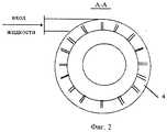
На фиг. 1 показан общий вид тепломассообменного аппарата; на фиг. 2 показан разрез аппарата по горизонтали на высоте кольцевой камеры; на фиг. 3 - разрез аппарата по горизонтали на высоте патрубка подачи очищаемых газов; на фиг. 4 - разрез баков по горизонтали. In FIG. 1 shows a general view of a heat and mass transfer apparatus; in FIG. 2 shows a horizontal section of the apparatus at the height of the annular chamber; in FIG. 3 - section of the apparatus horizontally at the height of the nozzle for supplying purified gases; in FIG. 4 - horizontal section of the tanks.
Сведения, подтверждающие возможность осуществления изобретения
Тепломассообменный аппарат состоит из цилиндрического корпуса 1, внутри которого коаксиально расположен газоход 2, образующий с форсункой 3 полый скруббер, а со струеобразователем с кольцевой камерой 4 - пенно-струйный безнасадочный скруббер, водяных насосов с фильтрами 5 и 6, центрального 7 и кольцевого 8 баков, расположенных коаксиально, патрубков ввода 9 и вывода 10 газов, патрубков слива орошающей жидкости 11 и 12, каплеуловителя 13, юбки 14 и холодильника 15.Information confirming the possibility of carrying out the invention
The heat and mass transfer apparatus consists of a cylindrical body 1, inside of which a
Тепломассообменный аппарат работает следующим образом. Heat and mass transfer apparatus operates as follows.
Очищаемые высокотемпературные газы, содержащие твердые и газообразные загрязняющие вещества, через патрубок 9 тангенциально подают в газоход 2, где их орошают форсункой 3. В газоходе 2 происходит интенсивное испарение орошающей жидкости (например, воды) и за счет этого резкое охлаждение газов. Содержащиеся в газах твердые частицы аэрозоля ударяются об омываемую орошающей жидкостью поверхность газохода, улавливаются и стекают с ней в центральный бак 7. The cleaned high-temperature gases containing solid and gaseous pollutants through the pipe 9 are tangentially fed into the
Очистка газов от твердых частиц аэрозоля осуществляется и каплями распыленной жидкости. Орошающую жидкость от центрального бака 7 фильтруют и насосом 5 вновь подают в форсунку 3. The cleaning of gases from solid aerosol particles is carried out by drops of atomized liquid. The irrigation fluid from the
Для предотвращения попадания орошающей жидкости полого скруббера в кольцевой бак 8, а орошающей жидкости пенно-струйного безнасадочного скруббера - в центральный бак 7 газоход 2 в нижней части имеет юбку 14 из двух встречных обечаек, расположенную выше уровней жидкости в баках. To prevent the irrigation fluid of the hollow scrubber from entering the
Нерастворимая часть твердых частиц аэрозоля оседает на дно центрального бака 7 и образует шлам, который по мере необходимости удаляют на переработку или захоронение. The insoluble part of the aerosol solid particles settles to the bottom of the
Очищенные от твердых частиц аэрозоля и насыщенные парами воды газы из полого скруббера поступают в зазор, образованный цилиндрическими корпусом 1 и газоходом 2, в котором струеобразователь с кольцевой камерой 4 создает струйную решетку орошающей жидкостью (например, водным раствором щелочи), подхватываемой очищаемыми газами с образованием высокотурбулизированного пенного слоя, где происходит дальнейшее охлаждение газов и их очистка от газообразных загрязняющих веществ. Контакт пенного слоя с внешней стенкой газохода 2 позволяет увеличивать охлаждение газа в полом скруббере. The gases cleaned from solid aerosol particles and saturated with water vapor from the hollow scrubber enter the gap formed by the cylindrical body 1 and the
Жидкость в кольцевом баке 8 охлаждается холодильником 15, ее температура ниже, чем у орошающей жидкости в центральном баке 7, и, поэтому, в пенном слое струйного скруббера происходит интенсивная конденсация паров воды, генерируемых за счет испарения воды в полом скруббере, на твердых частицах аэрозолей и благодаря этому их укрупнение, что резко повышает степень очистки газов от твердых частиц аэрозолей. Таким образом, в тепломассообменном аппарате происходит интенсивное охлаждение и очистка газов, а также раздельное улавливание твердых и газообразных загрязняющих веществ. The liquid in the
Благодаря кольцевому исполнению зоны пенного слоя и тому, что каналы кольцевой камеры струеобразователя направлены в центр струйного скруббера, а при таком расположении длина всех струй орошающей жидкости одинакова, повышается стабильность пенного слоя. Due to the annular execution of the zone of the foam layer and the fact that the channels of the annular chamber of the jet former are directed to the center of the jet scrubber, and with this arrangement, the length of all the jets of the irrigating liquid is the same, the stability of the foam layer increases.
Выше пенного слоя цилиндрический корпус аппарата 1 имеет расширение с образованием полости, где происходит падение скорости газов и сепарация каплеуловителем 13 капель жидкости, унесенных из пенного слоя. Above the foam layer, the cylindrical body of the apparatus 1 has an expansion with the formation of a cavity where the gas velocity drops and the droplet separator separates 13 drops of liquid carried away from the foam layer.
Орошающая жидкость из пенного слоя обрушивается вниз и по стенкам стекает в кольцевой бак 8, откуда насосом 6 вновь подается в кольцевую камеру струеобразователя 4, а очищенные газы через патрубок вывода газов 10 вентилятором (не показан) выбрасывают в атмосферу. Для опорожнения центрального и кольцевого баков 7 и 8 удаления образующихся шламов используют патрубки слива 11 и 12. Irrigating liquid from the foam layer falls down and flows down the walls into the
Техническим результатом предложенного аппарата по сравнению с прототипом является снижение материалоемкости, повышение степени очистки и охлаждения газов на 10-15%. The technical result of the proposed apparatus in comparison with the prototype is to reduce material consumption, increase the degree of purification and cooling of gases by 10-15%.
Пример. Определение эффективности работы тепломассообменного аппарата проводили на лабораторной установке производительностью 60 м3/час, выполненной в соответствии с формулой изобретения.Example. The determination of the efficiency of the heat and mass transfer apparatus was carried out in a laboratory installation with a capacity of 60 m 3 / h, made in accordance with the claims.
В лабораторную установку подавали отходящие газы процесса термического обезвреживания органических веществ. Газы имели температуру 250oC и содержали 165 мг/м3 твердых частиц аэрозолей, 25 мг/м3 SO2 и 24 мг/м3 NOx. Температура орошающих жидкостей в центральном и кольцевом баках составляла 65 и 40oC соответственно. В центральный бак первоначально была залита вода, а в кольцевой - 5%-ный раствор соды.Waste gases from the process of thermal neutralization of organic substances were supplied to the laboratory setup. The gases had a temperature of 250 ° C. and contained 165 mg / m 3 of solid aerosol particles, 25 mg / m 3 SO 2 and 24 mg / m 3 NO x . The temperature of the irrigation fluids in the central and annular tanks was 65 and 40 o C, respectively. Initially, water was poured into the central tank, and a 5% soda solution in the annular tank.
После 15 часов работы тепломассообменного аппарата в составе установки термического обезвреживания органических веществ в центральном баке накопилось 85% от первоначального количества пыли и 25% нитратов и сульфаты натрия, а в кольцевом - 15% пыли и до 75% нитратов и сульфатов натрия. Результаты анализа показали, что степень очистки газов от твердых частиц аэрозолей в тепломассообменном аппарате составляет 94,5%, а от оксидов серы и азота - 92 и 83% соответственно, что на 10-15% выше по сравнению с прототипом. Температура газов на выходе аппарата составляла 40-45oC.After 15 hours of operation of the heat and mass transfer apparatus as part of the thermal neutralization of organic substances in the central tank, 85% of the initial amount of dust and 25% of sodium nitrates and sulfates accumulated, and in the ring tank - 15% of dust and up to 75% of sodium nitrates and sulfates. The analysis results showed that the degree of gas purification from solid aerosol particles in the heat and mass transfer apparatus is 94.5%, and from sulfur and nitrogen oxides - 92 and 83%, respectively, which is 10-15% higher compared to the prototype. The temperature of the gases at the outlet of the apparatus was 40-45 o C.
Claims (4)
Priority Applications (1)
| Application Number | Priority Date | Filing Date | Title |
|---|---|---|---|
| RU97105748A RU2123375C1 (en) | 1997-04-10 | 1997-04-10 | Heat-and-mass exchange unit |
Applications Claiming Priority (1)
| Application Number | Priority Date | Filing Date | Title |
|---|---|---|---|
| RU97105748A RU2123375C1 (en) | 1997-04-10 | 1997-04-10 | Heat-and-mass exchange unit |
Publications (2)
| Publication Number | Publication Date |
|---|---|
| RU2123375C1 true RU2123375C1 (en) | 1998-12-20 |
| RU97105748A RU97105748A (en) | 1999-04-20 |
Family
ID=20191832
Family Applications (1)
| Application Number | Title | Priority Date | Filing Date |
|---|---|---|---|
| RU97105748A RU2123375C1 (en) | 1997-04-10 | 1997-04-10 | Heat-and-mass exchange unit |
Country Status (1)
| Country | Link |
|---|---|
| RU (1) | RU2123375C1 (en) |
Cited By (3)
| Publication number | Priority date | Publication date | Assignee | Title |
|---|---|---|---|---|
| CN102172456A (en) * | 2011-03-09 | 2011-09-07 | 上海化工研究院 | Novel percussive foam scrubber |
| RU2645143C2 (en) * | 2013-07-18 | 2018-02-15 | Кроноплюс Техникаль АГ | Method and device for purifying exhaust air produced during wood processing |
| RU2688761C1 (en) * | 2018-12-14 | 2019-05-22 | Сергей Васильевич Анискин | Foam mass exchange apparatus |
-
1997
- 1997-04-10 RU RU97105748A patent/RU2123375C1/en active
Cited By (4)
| Publication number | Priority date | Publication date | Assignee | Title |
|---|---|---|---|---|
| CN102172456A (en) * | 2011-03-09 | 2011-09-07 | 上海化工研究院 | Novel percussive foam scrubber |
| CN102172456B (en) * | 2011-03-09 | 2013-08-07 | 上海化工研究院 | Novel percussive foam scrubber |
| RU2645143C2 (en) * | 2013-07-18 | 2018-02-15 | Кроноплюс Техникаль АГ | Method and device for purifying exhaust air produced during wood processing |
| RU2688761C1 (en) * | 2018-12-14 | 2019-05-22 | Сергей Васильевич Анискин | Foam mass exchange apparatus |
Similar Documents
| Publication | Publication Date | Title |
|---|---|---|
| US4312646A (en) | Gas scrubbing tower | |
| KR950012520B1 (en) | Method and apparatus for the treatment of a waste gas containing dusts and chemical contaminants | |
| KR20010093132A (en) | Exhaust gas treating device | |
| CN214319573U (en) | Dust remover miropowder system of recycling | |
| CN208660703U (en) | A kind of processing system of landfill flare exhausts | |
| RU2038125C1 (en) | Method and device for cleaning gas flow | |
| RU2123375C1 (en) | Heat-and-mass exchange unit | |
| RU2650967C1 (en) | Method for purifying gases and device therefor | |
| KR20200020348A (en) | Wet ane cooling type gas cleaning apparatus | |
| KR101943914B1 (en) | Wet type filtering apparatus amd exhaust gas cleaning system with the same | |
| US5846272A (en) | Equipment for precipitation of pollutants from the off-gas of a pollutant source, particularly of a tentering frame | |
| JPH04131121A (en) | Method and apparatus for treating exhaust gas | |
| KR100467791B1 (en) | Heat exchanger self cleaning apparatus using mixture of water and solid particles | |
| KR101408859B1 (en) | Dust box for removing the particulate matters contained in the factory's waste gas | |
| RU2200053C1 (en) | Flue gas cleaning plant | |
| RU2144840C1 (en) | Evaporator-condenser unit | |
| KR100855905B1 (en) | Washer and method for purifying gases | |
| RU2079344C1 (en) | Apparatus for gasses purification (versions) | |
| RU2175101C1 (en) | Heat recovery and waste gas cleaning system | |
| RU2055293C1 (en) | Contact heat-exchanger | |
| JPS6012114A (en) | Apparatus for purifying treatment of exhaust gas | |
| US8778064B2 (en) | Green house gases filtration system | |
| SU850175A1 (en) | Gas scrubbing apparatus | |
| RU2038123C1 (en) | Vortex apparatus for cleaning gas | |
| CN209325873U (en) | Wet type photodissociation fume purifying programmable integrated process |