RU2120179C1 - White noise generator ( variants ) - Google Patents
White noise generator ( variants ) Download PDFInfo
- Publication number
- RU2120179C1 RU2120179C1 RU97109283A RU97109283A RU2120179C1 RU 2120179 C1 RU2120179 C1 RU 2120179C1 RU 97109283 A RU97109283 A RU 97109283A RU 97109283 A RU97109283 A RU 97109283A RU 2120179 C1 RU2120179 C1 RU 2120179C1
- Authority
- RU
- Russia
- Prior art keywords
- output
- input
- generator
- reference sequence
- white noise
- Prior art date
Links
Images


Abstract
Description
Изобретения объединены единым изобретательским замыслом, относятся к области вычислительной техники и могут быть использованы в качестве зашумляющихся устройств в различных каналах связи. The inventions are united by a single inventive concept, relate to the field of computer technology and can be used as noisy devices in various communication channels.
Известно устройство, генерирующее случайные импульсы типа белый шум [1, с.45, рис. 2.5]. Генератор случайных импульсов содержит каскадно соединенные генератор шума, усилитель шума, нелинейный элемент и квантователь, а также генератор периодических импульсов, выход которого подключен к второму входу квантователя. Выход квантователя является выходом генератора случайных импульсов. Однако данное устройство имеет невысокий динамический диапазон выходного белого шума, т.к. по своей технической сути представляет собой одноразрядный датчик двоичных чисел. Кроме того генератор - аналог не позволяет управлять параметрами выходного случайного процесса. A device is known that generates random pulses of the white noise type [1, p. 45, Fig. 2.5]. The random pulse generator contains a cascade-connected noise generator, a noise amplifier, a nonlinear element and a quantizer, as well as a periodic pulse generator, the output of which is connected to the second input of the quantizer. The quantizer output is the output of a random pulse generator. However, this device has a low dynamic range of the output white noise, because in its technical essence, it is a single-digit binary number sensor. In addition, the generator-analogue does not allow controlling the parameters of the output random process.
Наиболее близким к предлагаемым вариантам заявленных устройств по технической сущности является известный генератор белого шума [2, с.44, рис. 3.3] , содержащий регистр сдвига, в цепь обратной связи которого включена комбинаторная логическая схема, табличное постоянное запоминающее устройство, генератор шума, дискриминатор и цифроаналоговый преобразователь. Цифроаналоговый преобразователь представляет собой собственно цифроаналоговый преобразователь и сглаживающий фильтр, выход которого является выходом этого блока, а его входом - вход цифроаналогового преобразователя, выход которого подключен к входу сглаживающего фильтра. Выход генератора шума подключен к входу дискриминатора. Выход дискриминатора подключен к тактовому входу комбинаторной логической схемы. Выходы регистра сдвига одновременно подключены к одноименным входам комбинаторной логической схемы и табличному постоянному запоминающему устройству, выходы которого подключены к соответствующим входам цифро-аналогового преобразователя. Выход последнего является выходом генератора белого шума. Closest to the proposed variants of the claimed devices in technical essence is the well-known white noise generator [2, p. 44, Fig. 3.3], containing a shift register, in the feedback circuit of which is included a combinatorial logic circuit, a tabular read-only memory, a noise generator, a discriminator, and a digital-to-analog converter. The digital-to-analog converter is a digital-to-analog converter and a smoothing filter, the output of which is the output of this unit, and its input is the input of the digital-to-analog converter, the output of which is connected to the input of the smoothing filter. The output of the noise generator is connected to the input of the discriminator. The discriminator output is connected to the clock input of a combinatorial logic circuit. The outputs of the shift register are simultaneously connected to the inputs of the combinatorial logic circuit with the same name and the table-mounted read-only memory, the outputs of which are connected to the corresponding inputs of the digital-to-analog converter. The output of the latter is the output of a white noise generator.
Однако данный генератор имеет ряд недостатков. However, this generator has several disadvantages.
Во-первых, в известном устройстве невозможно осуществить регулировку параметров генерируемого случайного процесса - белый шум. Firstly, in the known device it is impossible to adjust the parameters of the generated random process - white noise.
Это объясняется тем, что для получения шума используется опорная m-значная последовательность псевдослучайных чисел (ПСЧ), которая формируется методом параллельного съема ПСЧ с n-ячеек регистра сдвига (где n - длина регистра сдвига). Однако известно [3, с.259], что максимальная разрядность m-разрядных ПСЧ, генерируемых параллельным способом, не может превышать регистра сдвига, т. е. m ≤ n. Следовательно при фиксированной длине регистра сдвига можно сформировать m-значную последовательность ПСЧ разрядности не больше n. В противном случае, при m > n, символы в разрядах m-значной последовательности ПСЧ окажутся линейно зависимыми и поэтому не будут удовлетворять статическим свойствам m-значных ПСЧ - равновероятность и случайность. This is explained by the fact that to obtain noise, the reference m-digit sequence of pseudorandom numbers (PSS) is used, which is formed by the method of parallel collection of PSC from n-cells of the shift register (where n is the length of the shift register). However, it is known [3, p. 259] that the maximum bit depth of m-bit MSS generated in a parallel way cannot exceed the shift register, that is, m ≤ n. Therefore, with a fixed length of the shift register, it is possible to form an m-digit sequence of PSShs of capacity no greater than n. Otherwise, for m> n, the symbols in the digits of the m-valued PSN sequence will turn out to be linearly dependent and therefore will not satisfy the static properties of the m-valued PSN - equiprobability and randomness.
Во-вторых, известный генератор имеет низкую устойчивость работы при высокой тактовой частоте генерирования белого шума. Secondly, the known generator has low operational stability at a high clock frequency of generating white noise.
При таком методе построения m-значной опорной последовательности ПСЧ возрастает число входов сумматоров по модулю два и их количество [3, с.256]. Так, при n = 20 можно получить m-значную последовательность ПСЧ разрядности не более 20. При этом среднее количество 20-ти входовых сумматоров по модулю два достигнет 10, а общее число входов 200. Такое количество обратных связей и входов сумматоров по модулю два в условиях высокой тактовой частоты формирования белого шума неизбежно приведет к сбоям работы генератора и общей неустойчивости функционирования устройства в целом. Это вызвано проблемой "гонок", включающих в логических элементах в таких случаях [4, с.149-164]. With this method of constructing an m-valued reference sequence, the number of inputs of the adders increases modulo two and their number [3, p.256]. So, with n = 20, you can get an m-digit sequence of PSC bits of no more than 20. In this case, the average number of 20 input adders modulo two will reach 10, and the total number of inputs 200. This number of feedbacks and inputs of adders modulo two in conditions of a high clock frequency of the formation of white noise will inevitably lead to malfunction of the generator and the overall instability of the functioning of the device as a whole. This is caused by the problem of "racing", including in logical elements in such cases [4, p.149-164].
В-третьих, сложность проектирования таких генераторов. Thirdly, the complexity of designing such generators.
При реализации генератора белого шума возникают большие проблемы его проектирования или синтеза, когда число ячеек регистра сдвига достигает 20 и больше. В этом случае нахождение наилучших обратных связей, которые нужно соединить с входами сумматора по модулю два (или оптимальной структуры) с целью получения требуемой m-значной последовательности ПСЧ, вообще не имеет аналитического решения [3, с.257]. When implementing a white noise generator, big problems arise in its design or synthesis, when the number of cells in the shift register reaches 20 or more. In this case, finding the best feedbacks that need to be connected to the inputs of the adder modulo two (or the optimal structure) in order to obtain the desired m-valued PSC sequence does not have an analytical solution at all [3, p.257].
Целью заявляемых объектов изобретений является разработка генератора белого шума (в трех вариантах), который позволяет управлять параметрами формируемого белого шума в широком частотно-динамическом диапазоне, при одновременном повышении устойчивости их функционирования. The purpose of the claimed objects of the invention is the development of a white noise generator (in three versions), which allows you to control the parameters of the generated white noise in a wide frequency-dynamic range, while increasing the stability of their functioning.
Поставленная цель в первом варианте достигается тем, что в известный генератор белого шума, содержащий генератор опорной последовательности, постоянное запоминающее устройство, выходы которого подключены к соответствующим выходам цифроаналогового преобразователя, выход которого подключен к входу сглаживающего фильтра, выход которого является выходом генератора белого шума, дополнительно введены генератор импульсов, формирователь сетки частот, m элементов И, где m - 2,3,.. и m - 1 генераторов опорной последовательности и блок управления. Выход генератора импульсов подключен к входу формирователя сетки частот, i-й выход формирователя сетки частот, где i = 1,2..., m, подключен к входу i-го генератора опорной последовательности и к второму входу i-го элемента И. Выходы m элементов И подключены к соответствующим m входам постоянного запоминающего устройства. I-й выход блока управления подключен к третьему входу i-го элемента И, а выход i-го генератора опорной последовательности подключен к первому входу i-го элемента И. The goal in the first embodiment is achieved by the fact that in a known white noise generator containing a reference sequence generator, a read-only memory, the outputs of which are connected to the corresponding outputs of a digital-to-analog converter, the output of which is connected to the input of a smoothing filter, the output of which is the output of a white noise generator, introduced a pulse generator, a frequency shaper, m elements And, where m - 2,3, .. and m - 1 generators of the reference sequence and the control unit. The output of the pulse generator is connected to the input of the frequency shaper, the i-th output of the frequency shaper, where i = 1,2 ..., m, is connected to the input of the i-th reference sequence generator and to the second input of the i-th element I. Outputs m elements AND are connected to the corresponding m inputs of read-only memory. The I-th output of the control unit is connected to the third input of the i-th element And, and the output of the i-th generator of the reference sequence is connected to the first input of the i-th element I.
I-й генератор опорной последовательности содержит регистр сдвига и сумматор по модулю два. Выходы k-го и (n+1)-го, где ![]()
![]()
Благодаря перечисленной совокупности существенных признаков предлагаемое устройство обеспечивает генерацию случайного процесса - белый шум с требуемыми параметрами, за счет получения m линейно-независимых опорных последовательностей псевдослучайных двоичных чисел и возможностью регулирования разрядностью формируемых m-значных псевдослучайных чисел. Кроме того, генератор, за счет упрощения аппаратурной реализации, обладает более высокой устойчивостью функционирования при повышенной частоте формирования белого шума. Due to the above set of essential features, the proposed device provides the generation of a random process - white noise with the required parameters, by obtaining m linearly independent reference sequences of pseudorandom binary numbers and the ability to control the bit depth of the generated m-digit pseudorandom numbers. In addition, the generator, due to the simplification of hardware implementation, has a higher operational stability at an increased frequency of white noise formation.
Поставленная цель во втором варианте достигается тем, что в известный генератор белого шума, содержащий генератор опорной последовательности, постоянное запоминающее устройство, выходы которого подключены к соответствующим входам цифроаналогового преобразователя, выход которого подключен к входу сглаживающего фильтра, выход которого является выходом генератора белого шума, дополнительно введены генератор импульсов, формирователь сетки частот, элемент ИЛИ, m элементов И, где m=2,3,.. и блок управления. Выход генератора импульсов подключен к входу формирователя сетки частот. I-й выход формирователя сетки частот, где i=1,2,..., m подключен к второму входу i-го элемента И и к i-му входу элемента ИЛИ. Выход элемента ИЛИ подключен к входу генератора опорной последовательности. Выход генератора опорной последовательности подключен к первым входам m элементов И. I-й выход блока управления подключен к третьему входу i-го элемента И, выходы которых подключены к m входам постоянного запоминающего устройства. The goal in the second embodiment is achieved by the fact that in a known white noise generator containing a reference sequence generator, a read-only memory, the outputs of which are connected to the corresponding inputs of a digital-to-analog converter, the output of which is connected to the input of a smoothing filter, the output of which is the output of a white noise generator, additionally introduced a pulse generator, a frequency shaper, an OR element, m AND elements, where m = 2,3, .. and a control unit. The output of the pulse generator is connected to the input of the frequency shaper. The I-th output of the frequency grid driver, where i = 1,2, ..., m is connected to the second input of the i-th AND element and to the i-th input of the OR element. The output of the OR element is connected to the input of the reference sequence generator. The output of the reference sequence generator is connected to the first inputs of m elements I. The I-th output of the control unit is connected to the third input of the i-th element And, the outputs of which are connected to m inputs of a permanent storage device.
Генератор опорной последовательности содержит регистр сдвига и сумматор по модулю два. Выходы j-го, где ![]()
![]()
Благодаря перечисленной совокупности существенных признаков предлагаемое устройство обеспечивает генерацию случайного процесса - белый шум с требуемыми параметрами, за счет формирования линейно-независимых опорных последовательностей псевдослучайных двоичных чисел и возможностью регулирования разрядностью m-значных псевдослучайных чисел. Кроме того, генератор, за счет упрощения аппаратурной реализации, обладает более высокой устойчивостью функционирования при повышенной частоте работы при формировании белого шума. Due to the above set of essential features, the proposed device provides the generation of a random process - white noise with the required parameters, due to the formation of linearly independent reference sequences of pseudorandom binary numbers and the ability to control the bit depth of m-digit pseudorandom numbers. In addition, the generator, due to the simplification of the hardware implementation, has a higher operational stability with an increased frequency of operation during the formation of white noise.
Поставленная цель в третьем варианте достигается тем, что в известный генератор белого шума, содержащий генератор опорной последовательности, постоянное запоминающее устройство, выходы которого подключены к соответствующим входам цифроаналогового преобразователя, выход которого подключен к входу сглаживающего фильтра, выход которого является выходом генератора белого шума, дополнительно введены генератор импульсов, формирователь сетки частот, элемент ИЛИ, m элементов И, где m=2,3,... и блок управления. Выход генератора импульсов подключен к входу формирователя сетки частот. I-й выход формирователя сетки частот подключен к второму входу i-го элемента И, где i= 1,2, . . . , m, и к i-му входу элемента ИЛИ. Выход элемента ИЛИ подключен к входу генератора опорной последовательности. Выход генератора опорной последовательности подключен к первым входам m элементов И. I-й выход блока управления подключен к третьему входу i-го элемента И, выходы которых подключены к m входам постоянного запоминающего устройства. К управляющему входу генератора опорной последовательности подключен выход регулируемого источника опорного напряжения. The goal in the third embodiment is achieved by the fact that in a known white noise generator containing a reference sequence generator, a read-only memory, the outputs of which are connected to the corresponding inputs of a digital-to-analog converter, the output of which is connected to the input of a smoothing filter, the output of which is the output of a white noise generator, introduced a pulse generator, a frequency shaper, an OR element, m AND elements, where m = 2,3, ... and a control unit. The output of the pulse generator is connected to the input of the frequency shaper. The I-th output of the frequency shaper is connected to the second input of the i-th element And, where i = 1,2,. . . , m, and to the i-th input of the OR element. The output of the OR element is connected to the input of the reference sequence generator. The output of the reference sequence generator is connected to the first inputs of m elements I. The I-th output of the control unit is connected to the third input of the i-th element And, the outputs of which are connected to m inputs of a permanent storage device. An output of an adjustable reference voltage source is connected to the control input of the reference sequence generator.
Генератор опорной последовательности содержит фиксатор мгновенных значений напряжения, информационный вход которого подключен к выходу источника шума, а выход к первому входу первого компаратора. Генератор линейно-изменяющегося напряжения, выход которого подключен к вторым входам первого и второго компараторов. Первый вход второго компаратора является управляющим входом генератора опорной последовательности. Выход D-триггера является выходом генератора опорной последовательности, на D-вход и C-выход которого подключены соответственно выходы элементов И и НЕ. На тактовый вход фиксатора мгновенных значений напряжения, вход генератора линейно-изменяющегося напряжения и вход элемента НЕ подключен вход генератора опорной последовательности. Выходы первого и второго компараторов подключены к входам элемента И. The reference sequence generator contains a clamp for instantaneous voltage values, the information input of which is connected to the output of the noise source, and the output to the first input of the first comparator. A ramp generator, the output of which is connected to the second inputs of the first and second comparators. The first input of the second comparator is the control input of the reference sequence generator. The output of the D-trigger is the output of the reference sequence generator, to the D-input and C-output of which the outputs of the AND and NOT elements are connected, respectively. At the clock input of the clamp of instantaneous voltage values, the input of the ramp generator and the input of the element are NOT connected to the input of the reference sequence generator. The outputs of the first and second comparators are connected to the inputs of the element I.
Благодаря перечисленной совокупности существенных признаков предлагаемое устройство обеспечивает генерацию случайного процесса - белый шум с требуемыми параметрами, за счет формирования линейно-независимых опорных последовательностей случайных двоичных чисел и возможностью регулирования разрядностью m-значных случайных чисел. Кроме того, генератор, за счет упрощения аппаратурной реализации, обладает более высокой устойчивостью функционирования при повышенной частоте работы при формировании белого шума. Due to the above set of essential features, the proposed device provides the generation of a random process - white noise with the required parameters, due to the formation of linearly independent reference sequences of random binary numbers and the ability to control the bit depth of m-digit random numbers. In addition, the generator, due to the simplification of the hardware implementation, has a higher operational stability with an increased frequency of operation during the formation of white noise.
Проведенный заявителем анализ уровня техники позволил установить, что аналоги, характеризующиеся совокупностью признаков, тождественных всем признакам заявляемого генератора белого шума, отсутствуют. Следовательно, заявляемое изобретение соответствует условию патентоспособности - "новизна". The analysis of the prior art by the applicant made it possible to establish that there are no analogs characterized by a combination of features identical to all the features of the claimed white noise generator. Therefore, the claimed invention meets the condition of patentability - "novelty."
Результаты поиска известных решений в данной и смежных областях техники с целью выявления признаков, совпадающих с отличительными от прототипа признаками заявляемого изобретения, показали, что они не следуют явным образом из уровня техники. Из определенного заявителем уровня техники не выявлена известность влияния предусматриваемых существенными признаками каждого из заявляемых изобретений преобразований на достижение указанного технического результата. Следовательно, заявляемое изобретение соответствует условию патентоспособности - "изобретательский уровень". Search results for known solutions in this and related fields of technology in order to identify features that match the distinctive features of the claimed invention from the prototype showed that they do not follow explicitly from the prior art. From the prior art determined by the applicant, the influence of the transformations provided for by the essential features of each of the claimed inventions on the achievement of the indicated technical result has not been revealed. Therefore, the claimed invention meets the condition of patentability - "inventive step".
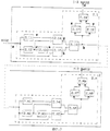
Заявляемый генератор белого шума поясняется чертежами, на которых: на фиг. 1 представлена схема заявляемого генератора по первому варианту; на фиг. 2 - схема опорного генератора по первому варианту; на фиг. 3 - схема формирователя сетки частот; на фиг. 4 - временные диаграммы, поясняющие принцип ФСЧ; на фиг. 5 - схема блока управления; на фиг. 6 представлена схема заявляемого генератора по второму варианту; на фиг. 7 - схема опорного генератора по второму варианту; на фиг. 8 представлена схема заявляемого генератора по третьему варианту; на фиг. 9 - схема опорного генератора по третьему варианту; на фиг. 10 - временные диаграммы поясняющие принцип работы генератора опорной последовательности по третьему варианту. The inventive white noise generator is illustrated by drawings, in which: in FIG. 1 presents a diagram of the inventive generator according to the first embodiment; in FIG. 2 is a diagram of a reference generator according to the first embodiment; in FIG. 3 is a diagram of a frequency grid former; in FIG. 4 - time diagrams explaining the principle of the FSF; in FIG. 5 is a diagram of a control unit; in FIG. 6 presents a diagram of the inventive generator according to the second embodiment; in FIG. 7 is a diagram of a reference generator according to the second embodiment; in FIG. 8 is a diagram of the inventive generator according to the third embodiment; in FIG. 9 is a diagram of a reference generator according to the third embodiment; in FIG. 10 is a timing diagram explaining the principle of operation of the reference sequence generator according to the third embodiment.
Заявляемое устройство по первому варианту содержит (фиг. 1) генератор импульсов (ГИ) 1, формирователь сетки частот (ФСЧ) 2, m генераторов опорной последовательности (ГОП) 3.1-3. m, m элементов И 4.1-4.m, цифроаналоговый преобразователь (ЦАП) 5, постоянное запоминающее устройство (ПЗУ) 6 и сглаживающий фильтр (СФ) 7, с выхода 8 которого снимается генерируемый белый шум, блок управления (БУ) 9. На вход СФ 7 подключен выход ЦАП 5. Выходы ПЗУ 6 подключены к одноименным входам ЦАП 5. На входы ПЗУ 5 подключены одноименные выходы m элементов И 4.1-4.m. Выход СФ 7 является выходом генератора белого шума. Выход ГИ 1 подключен к входу ФСЧ 2, i-й выход ФСЧ 2 подключен к второму входу i-го элемента И 4.1-4.m и входу i-го ГОП 3.1-3.m. Выходы i-го ГОП 3.1-3. m подключены к первому входу i-го элемента И 4.1-4.m. Выход БУ 9 подключен к третьему входу i-го элемента И 4.1-4.m. Выходы m элементов И подключены к m входам ПЗУ 5. The inventive device according to the first embodiment contains (Fig. 1) a pulse generator (GI) 1, a frequency shaper (FSF) 2, m generators of the reference sequence (GOP) 3.1-3. m, m elements AND 4.1-4.m, digital-to-analog converter (DAC) 5, read-only memory (ROM) 6 and smoothing filter (SF) 7, from the output of which 8 the generated white noise is removed, control unit (CU) 9. On the input of
I-й ГОП 3.1-3. m по первому варианту содержит (фиг. 2) регистр сдвига (РС) 3.1-3. m. 2 и сумматор по модулю два (СМД) 3.1.1-3.m.1. Выходы k-го и (n+1)-го разрядов РС 3.2.1-3.m.1 подключены соответственно к первому и второму входам СМД 3.1.1. Выход СМД 3.1.1-3.m.1 соединен с информационным входом РС 3.1.2-3.m.2, выход которого и его тактовый вход являются соответственно выходом и входом генератора опорной последовательности. I-GOP 3.1-3. m according to the first embodiment contains (Fig. 2) a shift register (RS) 3.1-3. m. 2 and an adder modulo two (SMD) 3.1.1-3.m.1. The outputs of the k-th and (n + 1) -th bits of RS 3.2.1-3.m.1 are connected respectively to the first and second inputs of SMD 3.1.1. The output of the SMD 3.1.1-3.m.1 is connected to the information input of the PC 3.1.2-3.m.2, the output of which and its clock input are respectively the output and input of the reference sequence generator.
ГИ 1 в первом варианте предназначен для формирования импульсов со скважностью T/t=2, где T - период следования импульсов, а t - длительность импульсов. Такие генераторы известны и описаны, например, в [3, с.240, рис. 7.9] .
ФСЧ 2 в первом варианте предназначен для формирования, в зависимости от входной частоты следования импульсов F=1/T скважности 2, на своих m выходах импульсов с частотами следования
F,F2,F4,...,F2(m-1). (1)
Схема построения ФСЧ 2 в первом варианте, реализующая такие задачи в заявляемом устройстве, приведена на фиг. 3 и состоит из блоков удвоения (БлУ) 2.1-2. m. При этом каждый блок удвоения 2.1-2.m содержит: элементы задержки (ЭЗ) 2.12-2. m2, 2.18-2. m8, элементы НЕ 2.11-2.m1, 2.13-1.m3, 2.17-1.m7, элементы И 2.14-2.m4, 2.15-2.m5, 2.19-2.m9, элементы ИЛИ 2.16-2.m6.The
F, F 2 , F 4 , ..., F 2 (m-1) . (1)
The construction scheme of the
ПЗУ 5 в первом варианте предназначено для преобразования входной опорной m-значной последовательности ПСЧ с равновероятным законом их распределения в m-значную последовательности ПСЧ с нормальным законом их распределения. Схема и принцип работы ПЗУ 5 известна и приведена, например, в [3, с.290, рис. 10.7]. ROM 5 in the first embodiment is intended to convert the input reference m-valued sequence of PSCs with an equally probable law of their distribution into an m-digit sequence of PSCs with the normal law of their distribution. The scheme and principle of operation of ROM 5 is known and is given, for example, in [3, p.290, Fig. 10.7].
ЦАП 6 в первом варианте предназначен для преобразования входного m-значного псевдослучайного числа с нормальным законом распределения в аналоговый случайный сигнал с тем же законом распределения - белый шум. Принцип работы и схема данного устройства известна и приведена в [4, с.185, рис. 6.5].
СФ 7 в первом варианте предназначен для подавления "выбросов" в выходном аналоговом сигнале белого шума, вызванных конечным временем тактовой частоты на выходе ЦАП 6. Схемы, принцип работы и расчет таких фильтров известны и приведены, например, в [1, с.66, рис. 4.11а].
БУ 9, в первом варианте, предназначен для управления параметрами случайного процесса: динамическим диапазоном и граничной частотой частотного спектра генерируемого белого шума. Схема БУ 9 с учетом решаемых задач может быть реализована в виде набора переключателей П 9.1-9.m, коммутирующих на третьи входы элементов И 3.1-3.m (4.1-3.m, 5.1-5.m) уровень напряжения логической единицы (Uлог"1") (Фиг. 5).
Заявляемое устройство, на примере первого варианта, работает следующим образом. The inventive device, as an example of the first embodiment, works as follows.
С выхода ГИ 1 последовательность импульсов скважности T/τ=2 поступает на вход ФСЧ 2 (фиг. 3). Каждый БлУ 2.1-2.m осуществляет удвоение частоты следования импульсов с сохранением скважности - 2 (фиг. 4 b). В БлУ 2.1 удвоение частоты следования входной последовательности импульсов осуществляется следующим образом. Последовательность импульсов (фиг. 4 a) поступает на ЭЗ 2.12, время задержки которой tлз1 = τ/2 (фиг. 4 z). И элемент НЕ 2.11 (фиг. 4 v), где они соответственно задерживаются и инвертируются. В момент одновременного присутствия на обоих входах элемента И 2.14 на его выходе будет сформирован импульс (фиг. 4 g). Аналогичный импульс будет сформирован и на выходе элемента И 2.15 в момент присутствия на первом входе последовательности инвертированных и задержанных импульсов, поступающих с входа БлУ 2.1 и входной последовательности импульсов (фиг. 4 a). На выходе элемента ИЛИ 2.16 будет сформирована удвоенная частота следования импульсов из последовательностей импульсов, поступающих на его вход с выходов элементов И 2.14 и 2.15 (фиг. 4 b). Если частота следования входной последовательности импульсов равна F=1/T при скважности, равной 2, то выходная удвоенная частота следования импульсов, будет суммой последовательностей удвоенной скважности с той же частотой следования импульсов,
T/(0,5t)+T/(0,5t)=2(T/0,5t),
где
F=1/2T, 2F=1/T.From the output of the
T / (0.5t) + T / (0.5t) = 2 (T / 0.5t),
Where
F = 1 / 2T, 2F = 1 / T.
Сформированная последовательность импульсов удвоенной частоты следования скважности 2 одновременно поступает на очередной вход БлУ 2.2 и на входы элементов НЕ 2.17 и ЭЗ 2.18, которая в двух последних элементах, соответственно, инвертируется (фиг. 4 x) и задерживается (фиг. 4 y). В момент одновременного присутствия на входах элемента И 2.19 данных импульсов будут сформированы короткие импульсы (фиг. 4 d) с частотой следования 2F и длительностью, равной 50..100 нс. Длительность будет определяться временем задержки в ЭЗ 2.19 tлз2, которая достаточна для формирования импульсов на выходе элемента И 2.19 и их использования в качестве импульсов тактовой частоты при функционировании генераторов опорных последовательностей ПСЧ 3.1-3.m.The generated pulse train of double the repetition rate of
Принцип работы следующих блоков удвоения 2.2-2.m аналогичен изложенному выше. Таким образом, входная последовательность импульсов, поступающая на вход ФСЧ 2, будет преобразована в сетку частот (1). The principle of operation of the following doubling blocks 2.2-2.m is similar to the above. Thus, the input pulse sequence fed to the input of the
Известно [4, с.191], что если из последовательности случайных двоичных чисел g(t), генерируемой с частотой F, формировать m-опорных последовательностей случайных двоичных чисел со следующими частотами следования
g1(t) 20F, g3(t) 21F, g3(t) 22F, ... , gn(t) 2n-1F, (4)
в которой
m-й разряд (самый старший) формируется с частотой 2n-1F, (m-1)-й разряд с частотой 2n-2F и т.д., а 1-й разряд (самый младший) с частотой 20F, то в результате получается m-значная последовательность случайных двоичных чисел

с равновероятным законом распределения.It is known [4, p.191] that if m-reference sequences of random binary numbers with the following repetition rates are formed from the sequence of random binary numbers g (t) generated with a frequency F
g 1 (t) 2 0 F, g 3 (t) 2 1 F, g 3 (t) 2 2 F, ..., g n (t) 2 n-1 F, (4)
wherein
The m-th discharge (the oldest) is formed with a frequency of 2 n-1 F, the (m-1) -th discharge with a frequency of 2 n-2 F, etc., and the 1st discharge (the youngest) with a frequency of 2 0 F, the result is an m-valued sequence of random binary numbers
with an equally probable distribution law.
Автокорреляционная функция Rσ(τ) m-значной последовательности случайных двоичных чисел будет удовлетворять требованию равновероятности и равняется взвешенной сумме автокорреляционных функций m-опорных последовательностей случайных двоичных чисел g1(t)2i-1 с коэффициентами, равными квадрату веса, соответствующему разряду числа
![]()
где
i - номер опорной последовательности, формирующей соответствующий i-y разряду m-значную последовательность случайных чисел.The autocorrelation function R σ (τ) of the m-valued sequence of random binary numbers will satisfy the requirement of equiprobability and is equal to the weighted sum of the autocorrelation functions of m-reference sequences of random binary numbers g 1 (t) 2 i-1 with coefficients equal to the square of the weight corresponding to the discharge of the number
![]()
Where
i is the number of the reference sequence forming the m-digit sequence of random numbers corresponding to the iy digit.
Из (3) - (6) следует, что к самым старшим разрядам необходимо предъявлять самые высокие требования "случайности", а к самым младшим - заниженные без ущерба качества m-значного случайного числа с равномерным законом распределения. From (3) - (6) it follows that the highest requirements of "randomness" must be presented to the highest ranks, and the lowest ones, without compromising the quality of an m-digit random number with a uniform distribution law, must be presented.
Поэтому m-значная последовательность ПСЧ формируется из m опорных последовательностей ПСЧ следующим образом. Therefore, the m-digit sequence of the PSC is formed from m reference sequences of the PSC as follows.
Последовательности тактовых импульсов с частотами (1) с соответствующих выходов ФСЧ 2 поступают на тактовые входы ГОП 3.1-3.m и на вторые входы элементов И 4.1-4. m. Учитывая, что первый ГОП 3.1 содержит i-ячеек, а каждый последующий ГОП 3.2-3. m на 2 ячейки больше предыдущего генератора опорной последовательности, на их выходах будут формироваться опорные последовательности ПСЧ со следующими периодами
iT,(i+2)T,..,(i+l)T. (7)
Время генерации последовательностей псевдослучайных чисел каждым ГОП 3.1-3. m будет одинаковым, т.к. частота следования тактовых импульсов относительно входной удваиваются от первого ГОП 3.1 к последующему, согласно (1). Таким образом, частота формирования одного m-значного псевдослучайного чиста от младшего разряда к старшему будет определяться (1) и подчиняться зависимости (6). Далее каждый разряд с выходов ГОП 3.1-3.m переносится в ПЗУ 5 через элементы И 4.1-4.n по разрешающему сигналу, поступающему на их второй вход с соответствующих выходов ФСЧ 2. Таким образом, на входе ПЗУ 5 будут формироваться, с частотой F2(m-1), m-значная последовательность ПСЧ с равновероятным законом распределения.The sequence of clock pulses with frequencies (1) from the corresponding outputs of the
iT, (i + 2) T, .., (i + l) T. (7)
The generation time of pseudo-random number sequences by each GOP 3.1-3. m will be the same since the pulse repetition rate relative to the input doubles from the first GOP 3.1 to the next, according to (1). Thus, the frequency of the formation of one m-valued pseudorandom is pure from the least significant to the highest will be determined (1) and obey the dependence (6). Next, each bit from the outputs of the GOP 3.1-3.m is transferred to ROM 5 through the elements And 4.1-4.n by the enable signal received at their second input from the corresponding outputs of the
Далее m-значная последовательность ПСЧ поступает на входы ПЗУ 5, где происходит преобразование статистических свойств - равномерного закона распределения m-значных ПСЧ в нормальный закон. Алгоритм такого преобразования известен и подробно описан в [2, с.178-179]. Полученная m-значная последовательность ПСЧ с нормальным законом распределения поступает на входы ЦАП 7, с выхода которого снимается аналоговый случайный сигнал - белый шум. Для сглаживания "выбросов" в белом шуме на выходе ЦАП 5 включен СФ 7. Next, the m-digit sequence of the MSS arrives at the inputs of the ROM 5, where the conversion of the statistical properties — the uniform distribution of the m-digit MSS into the normal law — takes place. The algorithm for such a conversion is known and described in detail in [2, pp. 178-179]. The obtained m-digit sequence of the PSC with the normal distribution law goes to the inputs of the
Для управления выходными параметрами белого шума в заявляемом генераторе предусмотрен блок управления 9. При включении переключателей П 9.1-9.m в положение "1" на третьи входы m элементов И 4.1-4.m подается уровень напряжения логической единицы (Uлог."1". В этом случае будет сформирована m-значная последовательность ПСЧ. После последовательных преобразований в ПЗУ 5 и ЦАП 6, на выходе 8 СФ 7 получится случайный процесс - белый шум, обладающий максимальными значениями границ частотного спектра и динамического диапазона.To control the output parameters of white noise in the inventive generator, a
Если, например, включить переключатели П 9.1-9.(m-j) в положение "1", то уровень напряжения логической единицы (Uлог."1") будет подан только на третьи входы (m-j) элементов И 4.1-4.(m-j). В этом случае будет сформирована (m-j)-значная последовательность ПСЧ и после аналогичных преобразований на выходе СФ 7 получится белый шум с другими параметрами. Границы частотного спектра и динамического диапазона белого шума будут меньше. Это объясняется тем, что (m-j)-значная последовательность ПСЧ формируется уже с тактовой частотой 2(m-j)F и периодом (m-j)T.If, for example, the switches P 9.1-9. (Mj) are turned on to the "1" position, then the voltage of the logical unit (U log. "1" ) will be applied only to the third inputs (mj) of the elements And 4.1-4. (Mj ) In this case, an (mj) -valued PSN sequence will be generated and, after similar transformations, the output of
По сравнению с прототипом заявляемый генератор в первом варианте может формировать на своем выходе белый шум с заданными параметрами граничной частоты частотного спектра случайного процесса и его динамического диапазона. Использование более простого способа формирования опорной m-значной последовательности ПСЧ позволяет генератору функционировать при высоких тактовых частотах более устойчиво, что позволяет использовать такие генераторы в качестве зашумляющих устройств каналов связи. Кроме того, проектирование и реализация таких генераторов с более широкими выходными возможностями значительно проще, так как это не вызывает трудностей при синтезе m-значных опорных генераторов ПСЧ и получения строгих аналитических решений при определении оптимальной структуры генераторов [4]. Compared with the prototype, the inventive generator in the first embodiment can generate white noise at its output with specified parameters of the boundary frequency of the frequency spectrum of the random process and its dynamic range. Using a simpler method of forming the reference m-digit sequence of the PSC allows the generator to operate at high clock frequencies more stably, which allows the use of such generators as noisy devices of communication channels. In addition, the design and implementation of such generators with wider output capabilities is much simpler, since it does not cause difficulties in the synthesis of m-valued PSC reference generators and in obtaining rigorous analytical solutions to determine the optimal structure of generators [4].
Заявляемое устройство по второму варианту содержит (фиг. 6) генератор импульсов (ГИ) 1, элемент ИЛИ 2, генератор опорной последовательности (ГОП) 3, формирователь сетки частот (ФСЧ) 4, m элементов И 5.1-5.m, постоянное запоминающее устройство (ПЗУ) 6, цифроаналоговый преобразователь (ЦАП) 7, сглаживающий фильтр (СФ) 8, с выхода 9 которого снимается сформированный белый шум, блок управления (БУ) 10. Вход СФ 8 подключен к выходу ЦАП 7. Выходы ПЗУ 6 подключены к одноименным входам ЦАП 7. Выход СФ 8 является выходом генератора белого шума. Выходы ПЗУ 6 подключены к соответствующим входам ЦАП 7, выход которого подключен к входу СФ 8. Выход СФ 8 является выходом генератора белого шума. Выход ГИ 1 подключен к входу ФСЧ 4, i-й выход которого подключен к второму входу i-го элемента И 5.1-5.m и к i-му входу элемента ИЛИ 2, а выход элемента ИЛИ 2 к входу ГОП 3. Выход ГОП 3 подключен к первым входам m элементов И. I-й выход БУ 10 подключен к третьему входу i-го элемента И 5.1-5.m, выходы которых подключены к m выходам ПЗУ 6. The inventive device according to the second embodiment contains (Fig. 6) a pulse generator (GI) 1, an OR
ГОП 3 по второму варианту содержит (фиг. 7) регистр сдвига (РС) 3.2 и сумматор по модулю два (СМД) 3.1. Выходы j-го l-го разрядов РС 3.2 подключены соответственно к первому и второму входам СМД 3.1. Выход СМД 3.1 соединен с информационным входом РС 3.2, выход которого и его тактовый вход являются соответственно выходом и входом ГОП 3.
Схемы, назначение ГИ 1, ФСЧ 4, ПЗУ 6, ЦАП 7, СФ 8 и БУ 10 во втором варианте аналогичен схемам и назначениям ГИ 1, ФСЧ 2, ПЗУ 5, ЦАП 6, СФ 7 и БУ 9 в первом варианте. Schemes, assignment of
Заявляемое устройство во втором варианте работает аналогично устройству в первом варианте, за исключением того, что во втором варианте ГОП 3 формирует только одну опорную последовательность псевдослучайных двоичных чисел, а m-значная последовательность ПСЧ формируется следующим образом. The inventive device in the second embodiment works similarly to the device in the first embodiment, except that in the second embodiment,
Последовательности тактовых импульсов с частотами (1) с соответствующих выходов ФСЧ 4 поступают на соответствующие входы элемента ИЛИ 2. С выхода последнего суммарная последовательность тактовых импульсов с частотой F2(m-1) поступает на тактовый вход ГОП 3 на выходе которого формируется последовательность псевдослучайных двоичных чисел. Одновременно последовательности тактовых импульсов с частотами (1) с соответствующих выходов ФСЧ 4 поступают на вторые входы элементов И 5.1-5.m. Поочередно переключая выход ГОП 3 к соответствующим входам ПЗУ 6 по закону (1). С частотой F2(m-1) на входе ПЗУ 6 будет сформирована m-значная последовательность ПСЧ с равновероятным законом распределения.The sequence of clock pulses with frequencies (1) from the corresponding outputs of the
По сравнению с прототипом заявляемый генератор во втором варианте, так же как и устройство в первом варианте, может формировать на своем выходе белый шум с заданными параметрами граничной частоты частотного спектра белого шума и его динамического диапазона. Позволяет формировать опорную последовательность ПСЧ любой значности, генератор не сложен и работает более устойчиво в условиях высокой тактовой частоты. Кроме того, проектирование и практическая реализация таких генераторов с более широкими выходными возможностями не вызывает трудностей, так как в отличие от прототипа существуют значительные трудности синтеза m-значных опорных генераторов ПСЧ, а отсутствие строгих аналитических решений при нахождении оптимальной структуры [4] выгодно отличает от прототипа. Compared with the prototype, the inventive generator in the second embodiment, like the device in the first embodiment, can generate white noise at its output with specified parameters of the cutoff frequency of the white noise frequency spectrum and its dynamic range. It allows you to form the reference sequence of the PSCH of any value, the generator is not complicated and works more stably in conditions of high clock frequency. In addition, the design and practical implementation of such generators with wider output capabilities does not cause difficulties, since, unlike the prototype, there are significant difficulties in the synthesis of m-valued PSC reference generators, and the lack of strict analytical solutions when finding the optimal structure [4] compares favorably with prototype.
Заявляемое устройство по третьему варианту содержит (фиг. 8) генератор импульсов (ГИ) 1, элемент ИЛИ 2, генератор опорной последовательности (ГОП) 3, формирователь сетки частот (ФСЧ) 4, регулируемый источник опорного напряжения (ИОН) 5, m элементов И 6.1-6.m, постоянное запоминающее устройство (ПЗУ) 7, цифроаналоговый преобразователь (ЦАП) 8, сглаживающий фильтр (СФ) 9, с выхода 10 которого снимается сформированный белый шум, блок управления (БУ) 11. Выход ГИ 1 подключен к входу ФСЧ 2, i-й выход которого подключен к второму входу i-го элемента И 6.1-6.m и к i-му входу элемента ИЛИ 2, а выход элемента ИЛИ 2 к входу ГОП 3, выход которого подключен к первым входам m элементов И 6.1-6. m. I-й выход БУ 11 подключен к третьему входу i-го элемента И 6.1-6.m, выходы которых подключены к m входам ПЗУ 7. К управляющему входу ГОП 3 подключен выход ИОН 5. The inventive device according to the third embodiment contains (Fig. 8) a pulse generator (GI) 1, an OR
ГОП 3 по третьему варианту содержит (фиг. 9) источник шума (ИШ) 3.1, фиксатор мгновенных значений напряжения (ФМН) 3.2, генератор линейно-изменяющегося напряжения (ГЛИН) 3.3, первый 3.4 и второй 3.5 компараторы, элемент И 3.6, D-триггер 3.7 и элемент НЕ 3.8. ГОП 3 содержит ФМЗН 3.2, информационный вход которого подключен к выходу ИШ 3.1, а выход к первому входу первого 3.4 компаратора. Выход ГЛИН 3.3 подключен к вторым входам первого 3.4 и второго 3.5 компараторов. Первый вход второго 3.5 компаратора является управляющим входом ГОП 3. Выход D-триггера 3.7 является выходом ГОП 3. На D-вход и C-вход D-триггера 3.7 подключены соответственно выходы элементов И 3.6 и НЕ 3.8. На тактовый вход ФМЗН 3.2, вход ГЛИН 3.3 и вход элемента НЕ 3.8 подключен вход ГОП 3, выходы первого 3.4 и второго 3.5 компараторов подключены к входам элемента И 3.6.
Схемы и назначение ГИ 1, ФСЧ 4, ПЗУ 7, ЦАП 8, СФ 9 и БУ 11 в третьем варианте аналогичен схемам и назначениям ГИ 1, ФСЧ 2, ПЗУ 5, ЦАП 6, СФ 7 и БУ 9 в первом варианте. Schemes and purpose of
ИОН 5 предназначен для выдачи на своем выходе управляемой величины опорного напряжения. Схемы таких управляемых источников опорного напряжения известны и приведены, например, в [6, стр. 78, рис. 2.31a]. ION 5 is designed to provide at its output a controlled value of the reference voltage. The schemes of such controlled sources of reference voltage are known and are given, for example, in [6, p. 78, Fig. 2.31a].
Заявляемое устройство в третьем варианте работает аналогично устройству в первом и во втором вариантах, за исключением того, что в третьем варианте ГОП 3 формирует только одну опорную последовательность случайных двоичных чисел (ПСДЧ), а m-значная последовательность ПСДЧ формируется следующим образом. The inventive device in the third embodiment works similarly to the device in the first and second variants, except that in the third embodiment,
В третьем варианте ГОП 3 формирует опорную m-значную последовательность ПСДЧ следующим образом (фиг. 9). In the third embodiment,
Сформированные последовательности тактовых импульсов с частотами (1) с соответствующих выходов ФСЧ 4 поступают на соответствующие входы элемента ИЛИ 2. С выхода последнего суммарная последовательность тактовых импульсов с частотой F2(m-1) поступает на тактовый вход ГОП 3. С тактового входа ГОП 3 последовательность тактовых импульсов поступает на управляющий вход ФМЗ 3.2 (фиг. 10 d). В ФМЗ 3.2 запоминается напряжение (фиг. 10 b), соответствующее в этот момент времени мгновенному значению напряжения шума на выходе ИШ 3.1 (фиг. 10 a). Одновременно запускается ГЛИН 3.3. В момент равенства напряжений на выходах ГЛИН 3.3 и ФМЗ 3.2 (фиг. 10 c,b) срабатывает первый компаратор 3.4. В результате на выходе первого компаратора 3.4 формируется импульс (фиг. 10 e) с уровнем напряжения, равным логической единице. Длительность сформированного таким образом импульса равномерно распределена на временном интервале ]0,T[. Это объясняется тем, что выборка мгновенных значений напряжений из реализации случайного процесса ИШ 3.1 равномерно распределена в некотором интервале напряжений шума. В зависимости от величины уровня опорного напряжения на втором входе второго компаратора 3.5 (фиг. 10 f) в момент его равенства с уровнем линейно-изменяющегося напряжения на первом входе, на выходе будет сформирован импульс. Длительность этого импульса пропорциональна уровню опорного напряжения и лежит на интервале ]0,T[.The generated sequences of clock pulses with frequencies (1) from the corresponding outputs of the
Пусть уровень опорного напряжения выбран так, что длительность импульсов формируемого на выходе второго компаратора 3.5 равняется T/2. Тогда вероятность совпадения во времени импульсов с выхода первого компаратора 3.4 с импульсами поступающих с второго компаратора 3.5 будет равна 0.5. В данном случае вероятность можно интерпретировать как отношение мер - длительности сформированного импульса T/2 к длительности T, на которой формируется длительность импульса с равновероятным законом распределения Δt [5, с.17-18]
P = (T/2) / T = 0,5.Let the level of the reference voltage be selected so that the pulse duration generated at the output of the second comparator 3.5 is equal to T / 2. Then the probability of coincidence in time of the pulses from the output of the first comparator 3.4 with the pulses coming from the second comparator 3.5 will be 0.5. In this case, the probability can be interpreted as the ratio of measures - the duration of the generated pulse T / 2 to the duration T, on which the pulse duration is formed with the equally probable distribution law Δt [5, p.17-18]
P = (T / 2) / T = 0.5.
Если уменьшить длительность импульса на выходе второго компаратора 3.4, то и уменьшится вероятность формируемой случайной последовательности на выходе ГОП 3. If we reduce the pulse duration at the output of the second comparator 3.4, then the probability of the generated random sequence at the output of the
Для получения бинарной (двоичной) случайной последовательности сигналов предназначен D-триггер. Последовательность случайных сигналов с выхода элемента И 3.6 поступает на D-вход D-триггера, который переключается по инвертируемым тактовым сигналам на своем C-входе в состояние, предписываемое сигналом на D-входе. Таким образом, на выходе ГОП будет получена бинарная последовательность случайных сигналов вероятность появления которых можно регулировать путем изменения уровня напряжения на выходе ИОН 5 (фиг. 10 u). To obtain a binary (binary) random sequence of signals, a D-trigger is intended. The sequence of random signals from the output of AND 3.6 is fed to the D-input of the D-flip-flop, which switches over the inverted clock signals at its C-input to the state prescribed by the signal at the D-input. Thus, a binary sequence of random signals will be obtained at the output of the GOP, the probability of occurrence of which can be controlled by changing the voltage level at the output of ION 5 (Fig. 10 u).
По сравнению с прототипом заявляемый генератор в третьем варианте так же, как устройство в первых двух вариантах, может формировать на своем выходе белый шум с заданными параметрами граничной частоты частотного спектра белого шума и его динамического диапазона. Позволяет формировать опорную последовательность ПСДЧ любой значности, значительно упрощает и позволяет работать генератору более устойчиво при высоких тактовых частотах. Кроме того, проектирование и реализация таких генераторов с более широкими выходными возможностями значительно проще, так как это не связано с трудностями синтеза m-значных опорных генераторов ПСДЧ и нахождения строгих аналитических решений при определении их обратных связей [4]. Compared with the prototype, the inventive generator in the third embodiment, in the same way as the device in the first two versions, can generate white noise at its output with the specified parameters of the cutoff frequency of the white noise frequency spectrum and its dynamic range. It allows you to form the reference sequence of the PSCH of any value, greatly simplifies and allows the generator to work more stably at high clock frequencies. In addition, the design and implementation of such generators with wider output capabilities is much simpler, since this is not connected with the difficulties of synthesizing m-valued reference PSDCH generators and finding rigorous analytical solutions to determine their feedbacks [4].
Источники информации
1. Бобнев М.П. Генерирование случайных сигналов. М.: Энергия, 1971, 240 с.Sources of information
1. Bobnev M.P. Random signal generation. M .: Energy, 1971, 240 p.
2. Денда В. Шум как источник информации: Пер. с нем. -М.: МИР, 1993. -192 с., ил. 2. Denda V. Noise as a source of information: Per. with him. -M .: MIR, 1993. -192 p., Ill.
3. Потемкин И.С. Функциональные узлы цифровой автоматики. -М.: Энергоатомиздат, 1988. -300 с., ил. 3. Potemkin IS Functional units of digital automation. -M .: Energoatomizdat, 1988. -300 p., Ill.
4. Яковлев В.В. Стохастические вычислительные машины. -Л.: Машиностроение, 1974, с.191. 4. Yakovlev V.V. Stochastic computers. -L.: Mechanical Engineering, 1974, p.191.
5. Каневский З.М. Вероятностные задачи в радиотехнике (Б-ка по радиоэлектронике, вып.3). - М. -Л., Энергия, 176 с., ил. 5. Kanevsky Z.M. Probabilistic problems in radio engineering (B-k on electronics, issue 3). - M. -L., Energy, 176 p., Ill.
6. Микросхемы и их применение: Справочное пособие/ В.А.Батушев и др. -М. : Радио и связь, 1983 - 272 с., ил. - (Массовая радиобиблиотека; вып.1070). 6. Microcircuits and their application: Reference manual / V.A. Batushev et al. -M. : Radio and communication, 1983 - 272 p., Ill. - (Mass Radio Library; issue 1070).
Claims (6)
Priority Applications (1)
| Application Number | Priority Date | Filing Date | Title |
|---|---|---|---|
| RU97109283A RU2120179C1 (en) | 1997-06-02 | 1997-06-02 | White noise generator ( variants ) |
Applications Claiming Priority (1)
| Application Number | Priority Date | Filing Date | Title |
|---|---|---|---|
| RU97109283A RU2120179C1 (en) | 1997-06-02 | 1997-06-02 | White noise generator ( variants ) |
Publications (2)
| Publication Number | Publication Date |
|---|---|
| RU2120179C1 true RU2120179C1 (en) | 1998-10-10 |
| RU97109283A RU97109283A (en) | 1999-01-27 |
Family
ID=20193754
Family Applications (1)
| Application Number | Title | Priority Date | Filing Date |
|---|---|---|---|
| RU97109283A RU2120179C1 (en) | 1997-06-02 | 1997-06-02 | White noise generator ( variants ) |
Country Status (1)
| Country | Link |
|---|---|
| RU (1) | RU2120179C1 (en) |
Cited By (1)
| Publication number | Priority date | Publication date | Assignee | Title |
|---|---|---|---|---|
| RU2696019C1 (en) * | 2019-03-11 | 2019-07-30 | Акционерное общество "Концерн "Созвездие" | Digital radio device with built-in masking of electromagnetic channel of speech information leakage |
-
1997
- 1997-06-02 RU RU97109283A patent/RU2120179C1/en active
Non-Patent Citations (1)
| Title |
|---|
| Денда В. Шум как источник информации. Пер. с нем. -М.: Мир, 1993, с. 44, фиг.3.3. * |
Cited By (1)
| Publication number | Priority date | Publication date | Assignee | Title |
|---|---|---|---|---|
| RU2696019C1 (en) * | 2019-03-11 | 2019-07-30 | Акционерное общество "Концерн "Созвездие" | Digital radio device with built-in masking of electromagnetic channel of speech information leakage |
Similar Documents
| Publication | Publication Date | Title |
|---|---|---|
| KR20020013934A (en) | A parallel analog-to-digital converter | |
| GB2357610A (en) | Method of generating a non-repeating sequence of numbers | |
| RU2120179C1 (en) | White noise generator ( variants ) | |
| RU2163027C2 (en) | Pseudorandom sequence generator (alternatives) | |
| RU2081450C1 (en) | Generator of n-bit random sequence | |
| US5761100A (en) | Period generator for semiconductor testing apparatus | |
| US4998263A (en) | Generation of trigger signals | |
| RU2030092C1 (en) | Digital frequency synthesizer | |
| RU2080651C1 (en) | Generator of random n-bit binary numbers | |
| RU2022332C1 (en) | Orthogonal digital signal generator | |
| SU1168966A1 (en) | Processor for transforming digital signals into haar-like bases | |
| SU903873A1 (en) | Generator of random numbers for simulating general population by objects of a sample | |
| SU942012A1 (en) | Psedo-random number generator pseudo-random sequence generator | |
| SU1508350A2 (en) | Delta-modulator | |
| RU1833907C (en) | Method for transmission and reception of digital information and system for its realization | |
| SU951640A1 (en) | Noise generator | |
| RU2246174C1 (en) | Poisson pulse stream generator | |
| SU1198533A1 (en) | Device for simulating phase jitter of pulses of code sequence | |
| SU1118990A1 (en) | Random signal generator | |
| SU902248A1 (en) | Device for conversion of time interval to code | |
| SU742910A1 (en) | Pseudorandom binary train generator | |
| SU1543401A1 (en) | Digital function generator | |
| SU1711159A1 (en) | Generator of pseudorandom signals | |
| SU638995A1 (en) | Controllable probabilistic converter | |
| SU1177877A1 (en) | Random signal generator |