RU2100542C1 - Device for float finish and smoothing of surfaces - Google Patents
Device for float finish and smoothing of surfaces Download PDFInfo
- Publication number
- RU2100542C1 RU2100542C1 RU93010780A RU93010780A RU2100542C1 RU 2100542 C1 RU2100542 C1 RU 2100542C1 RU 93010780 A RU93010780 A RU 93010780A RU 93010780 A RU93010780 A RU 93010780A RU 2100542 C1 RU2100542 C1 RU 2100542C1
- Authority
- RU
- Russia
- Prior art keywords
- working body
- vibrator
- halves
- smoothing
- working
- Prior art date
Links
Images

Landscapes
- Apparatuses For Generation Of Mechanical Vibrations (AREA)
Abstract
Description
Изобретение относится к строительным инструментам, а именно к устройствам для затирки оштукатуренных поверхностей и заглаживания цементно-песчаных и бетонных поверхностей. The invention relates to construction tools, and in particular to devices for grouting plastered surfaces and smoothing cement-sand and concrete surfaces.
Известно устройство для заглаживания поверхностей строительных изделий, включающее привод, упругую муфту, траверсу с кронштейнами и лопастями [1]
К недостаткам устройства относится громоздкость системы, большое количество механических частей, трудоемкость перемещения вдоль обрабатываемой поверхности.A device for smoothing the surfaces of building products, including a drive, an elastic coupling, a traverse with brackets and blades [1]
The disadvantages of the device include the bulkiness of the system, a large number of mechanical parts, the complexity of moving along the work surface.
Известно также затирочное устройство, содержащее корпус, размещенный в нем электромагнитный вибратор, жестко связанный с дугообразными звеньями и рабочий орган [2]
Известная конструкция не предусматривает вибрационного нагружения рабочих элементов. Значительные габариты и вес затрудняют работу и снижают эффективность его эксплуатации. Конструкция со значительным количеством механических частей снижает эффект контакта с поверхностью, следовательно, КПД.Also known is a trowel device containing a housing, an electromagnetic vibrator placed therein, rigidly connected with arcuate links and a working body [2]
The known design does not provide for vibration loading of working elements. Significant dimensions and weight complicate the work and reduce the efficiency of its operation. A design with a significant number of mechanical parts reduces the effect of contact with the surface, therefore, the efficiency.
Задача изобретения повышение производительности, КПД и качества отделки поверхности. Указанная задача решается тем, что устройство снабжено магнитострикционным вибратором с плотно связанными с ним изогнутыми заданной длины усилителями амплитуды колебаний, которые представляют собой дугообразные, удлиненные звенья экспоненциальной формы, в значительной степени увеличивающие амплитуду колебаний от магнитострикционного вибратора к свободному концу усилителей амплитуды колебаний. При этом вибрация от усилителей колебаний передается на половины составного рабочего органа. Равные продольные части рабочего органа соединены для жесткости упругой связью. Продольное перемещение устройства осуществляется вручную, удержанием корпуса вибратора. The objective of the invention is to increase productivity, efficiency and surface finish. This problem is solved by the fact that the device is equipped with a magnetostrictive vibrator with densely coupled curved given length amplifiers of oscillation amplitude, which are arched, elongated links of exponential shape, significantly increasing the amplitude of oscillations from the magnetostrictive vibrator to the free end of the amplifiers of the amplitude of the oscillations. In this case, vibration from vibration amplifiers is transmitted to half of the composite working body. Equal longitudinal parts of the working body are connected for stiffness by an elastic bond. The longitudinal movement of the device is carried out manually by holding the vibrator body.
С целью повышения производительности каждая половина рабочего органа воспринимает вибрацию от своего свободного конца усилителя колебаний, разнесенных в противоположные стороны по оси вибратора, создавая тем самым противофазное поперечное нагружение инструмента и контакт на другом конце волновода через опосредствование упругой связи. Кроме того, упругая связь в поперечном направлении приводит к убыли колебаний, создавая эффект сглаживания обрабатываемого материала, а направленные в противофазе перпендикулярные к рабочему органу (и обрабатываемой поверхности) знакопеременные интенсивные вибрационные колебания будут создавать эффект уплотнения. In order to increase productivity, each half of the working body perceives vibration from its free end of the vibration amplifier, spaced in opposite directions along the axis of the vibrator, thereby creating an antiphase transverse loading of the tool and contact at the other end of the waveguide through the mediation of elastic coupling. In addition, the elastic bond in the transverse direction leads to a decrease in vibrations, creating a smoothing effect of the material being processed, and alternating intense vibrational vibrations directed in antiphase to the working body (and the treated surface) will create a compaction effect.
Рабочий орган устройства, закрепленный осью центрально, разделенный на две продольные равные части, воспринимает знакопеременную вибрацию от изогнутых и разнесенных вдоль оси определенной длины усилителей колебаний посредством контакта свободного конца волновода с одной из половин рабочего органа. Сочетание продольного перемещения со знакопеременной противофазной интенсивной вибрацией как вдоль рабочего органа, так и поперек его тела создает интенсивное заглаживающее движение устройства, а направление колебательного перпендикулярно обрабатываемой поверхности движения создает поверхностное уплотнение, что приводит к повышению качества обрабатываемой поверхности. The working body of the device, fixed centrally by the axis, divided into two equal longitudinal parts, receives alternating vibration from vibration amplifiers bent and spaced along the axis of a certain length through the contact of the free end of the waveguide with one of the halves of the working body. The combination of longitudinal movement with alternating antiphase intense vibration both along the working body and across its body creates an intense smoothing movement of the device, and the direction of the oscillating perpendicular to the machined surface of the movement creates a surface seal, which leads to an increase in the quality of the machined surface.
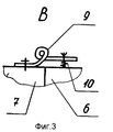
На фиг. 1 изображен общий вид устройства; на фиг. 2 вид Б на фиг. 1; на фиг. 3 вид В на фиг. 1. In FIG. 1 shows a General view of the device; in FIG. 2, view B in FIG. one; in FIG. 3, view B in FIG. one.
В полости корпуса 1 с карманом А для захвата рукой рабочего установлен магнитострикционный вибратор 2, питающийся током по кабелю 3, плотно прикрепленному к нему изогнутыми и разнесенными вдоль оси вибратора с плавно уменьшающимся сечением усилителями колебаний определенной длины, свободный конец которых вставляется в фиксатор (стакан) 5 рабочего органа 6, состоящего из двух равных продольных частей 6 и 7 (вид Б) и закрепленных центрально на корпус 1 осью 8. Части 6 и 7 рабочего органа соединены для жесткости упругой связью одновитковой плоской пружиной 9, один конец которой жестко прикреплен к левой половине (с противоположной стороны к правой) рабочего органа 7, второй прикреплен к правой половине (с противоположной стороны наоборот) рабочего органа 6 посредством регулирующей пружины 10 (вид В). In the cavity of the housing 1 with a pocket A, a magnetostrictive vibrator 2 is mounted to capture the worker’s hand, powered by a current through a cable 3, tightly attached to it with curved and spaced apart along the axis of the vibrator vibrational amplifiers of a certain length, the free end of which is inserted into the retainer (glass) 5 of the
Устройство работает следующим образом. The device operates as follows.
По кабелю 3 подается переменный ток звуковой частоты на магнитострикционный вибратор 2, который плотно соединен с двух концов изогнутыми и разнесенными вдоль оси вибратора усилителями амплитуды колебаний 4. Усилители амплитуды колебаний 4 выполнены вполне определенной длины, чтобы можно было получить жесткое соединение их с корпусом 1, при этом расстояние между опорами соединения должно быть кратным полуволне. Свободные концы усилителя 4 изогнуты в сторону рабочего органа, состоящего из двух половин 6 и 7, перпендикулярно обрабатываемой поверхности и вставлены в фиксаторы (стакан) 5, жестко закрепленные справа от вибратора на половине рабочего органа 6 и слева от вибратора на половине рабочего органа 7. Обе половины рабочего органа 6 и 7 связаны центрально с корпусом 1 осью 8. Упругая волна через усилители колебаний 4 и стаканы 5 передается на рабочий орган 6 и 7. Последние совершают при этом противофазное колебательное движение. Если половина рабочего органа 6 начинает колебание по часовой стрелке, то вторая половина 7 против часовой. Таким образом, через центральную ось 8 каждая из половин как бы одновременно воздействует вибрационной нагрузкой на обрабатываемую поверхность. The cable 3 is supplied with an alternating current of sound frequency to a magnetostrictive vibrator 2, which is tightly connected at both ends by vibration amplifiers 4. The amplifiers of oscillations 4 are made of a quite certain length so that they can be rigidly connected to the housing 1, the distance between the supports of the connection should be a multiple of half a wave. The free ends of the amplifier 4 are bent towards the working body, consisting of two
Чтобы не терялся контакт между усилителями колебаний 4 и им соответствующим стаканом 5 половины 6 и 7 рабочего органа снабжены упругой связью 9, представляющей собой плоскую одновитковую пружину, один конец которой жестко прикреплен к левой половине 7 рабочего органа (вид Б), другой конец связан с правой половиной 6 рабочего органа через регулируемую пружину 10. Регулируемая пружина 10 отжимает половину 6 вниз, а правую вверх, прижимая тем самым стакан 5 к свободным концам усилителя колебаний 4. In order not to lose contact between the oscillation amplifiers 4 and the corresponding cup 5, the
С другого конца половины 6 и 7 рабочего органа соединены упругой связью наоборот, т. е. плоская пружина соединена жестко с половиной 6 и т.д. При усталостном ослаблении пружин 10 они регулируются увеличением их хода. Кроме создания постоянного контакта стаканов 5 половин 6 и 7 рабочего органа с концами усилителя 4, упругая связь сглаживает колебания по всей поверхности обрабатываемого материала, создавая эффект постоянного виброконтактного нагружения. On the other end, the
Перемещение устройства вдоль обрабатываемой поверхности осуществляется захватом рукой верхней части корпуса 1 (в месте установки вибратора 2) через нишу А. The device is moved along the work surface by hand grabbing the upper part of the housing 1 (at the place of installation of the vibrator 2) through the niche A.
Таким образом, применяя направленное перпендикулярно к обрабатываемой поверхности, интенсивное противофазное вибрационное воздействие на каждую половину рабочего органа и его перемещение вдоль обрабатываемой поверхности, получают контактное по всей поверхности суммарное рабочее вибродинамическое знакопеременное нагружение рабочего органа, оказывающее как интенсивное сглаживающее, так и уплотняющее действие на обрабатываемую строительную поверхность. Thus, by applying perpendicular to the surface to be treated, intense antiphase vibrational impact on each half of the working body and its movement along the surface to be processed, the total working vibrodynamic alternating working load of the working body that has both intense smoothing and sealing effect on the processed surface is obtained building surface.
Указанное выполнение устройства обеспечивает повышение производительности за счет высокочастотного знакопеременного нагружения половин рабочего органа в результате эффекта противофазного вибрационного нагружения концов двух половин рабочего органа. В новых условиях обработки поверхностей снижается энергоемкость, затраты труда и увеличивается КПД, так как на один рабочий орган приходится вся энергия магнитострикционного вибратора. The specified implementation of the device provides increased productivity due to high-frequency alternating loading of the halves of the working body as a result of the effect of out-of-phase vibration loading of the ends of the two halves of the working body. In the new conditions for surface treatment, energy consumption, labor costs are reduced and efficiency is increased, since all the energy of a magnetostrictive vibrator is accounted for by one working body.
Claims (1)
Priority Applications (1)
| Application Number | Priority Date | Filing Date | Title |
|---|---|---|---|
| RU93010780A RU2100542C1 (en) | 1993-03-01 | 1993-03-01 | Device for float finish and smoothing of surfaces |
Applications Claiming Priority (1)
| Application Number | Priority Date | Filing Date | Title |
|---|---|---|---|
| RU93010780A RU2100542C1 (en) | 1993-03-01 | 1993-03-01 | Device for float finish and smoothing of surfaces |
Publications (2)
| Publication Number | Publication Date |
|---|---|
| RU93010780A RU93010780A (en) | 1995-04-20 |
| RU2100542C1 true RU2100542C1 (en) | 1997-12-27 |
Family
ID=20137970
Family Applications (1)
| Application Number | Title | Priority Date | Filing Date |
|---|---|---|---|
| RU93010780A RU2100542C1 (en) | 1993-03-01 | 1993-03-01 | Device for float finish and smoothing of surfaces |
Country Status (1)
| Country | Link |
|---|---|
| RU (1) | RU2100542C1 (en) |
Cited By (1)
| Publication number | Priority date | Publication date | Assignee | Title |
|---|---|---|---|---|
| CN110076880A (en) * | 2019-05-28 | 2019-08-02 | 北京凯盛建材工程有限公司 | A kind of floating device and smooth out method |
-
1993
- 1993-03-01 RU RU93010780A patent/RU2100542C1/en active
Non-Patent Citations (1)
| Title |
|---|
| SU, авторское свидетельство, 1015064, кл. E 04 F 21/16, 1982. SU, авторское свидетельство, 87931, кл. E 04 F 21/16, 1949. * |
Cited By (1)
| Publication number | Priority date | Publication date | Assignee | Title |
|---|---|---|---|---|
| CN110076880A (en) * | 2019-05-28 | 2019-08-02 | 北京凯盛建材工程有限公司 | A kind of floating device and smooth out method |
Similar Documents
| Publication | Publication Date | Title |
|---|---|---|
| JP4304545B2 (en) | Work implements operated by handgrip | |
| JP7211964B2 (en) | Personal care appliances | |
| US5134334A (en) | Ultrasonic linear motor | |
| SE9503515D0 (en) | Felling machining | |
| EA200001016A1 (en) | ACOUSTIC DEVICE | |
| US5837298A (en) | Piezoelectrically-actuated vibrating surface-finishing tool | |
| JPH05137190A (en) | Device for emitting ultrasonic energy into liquid | |
| US6017398A (en) | Immersed metal cleaning by subjecting object to natural resonant frequency | |
| RU2100542C1 (en) | Device for float finish and smoothing of surfaces | |
| US6150752A (en) | Acoustic transducer with liquid-immersed, pre-stressed piezoelectric actuator in acoustic impedance matched transducer housing | |
| US3376798A (en) | Sonic trowel | |
| KR100462351B1 (en) | Method for activating a sieve frame with ultrasounds | |
| US6075310A (en) | Acoustic transducer with liquid-immersed, pre-stressed piezoelectric actuator in acoustic impedance matched transducer housing | |
| US6013972A (en) | Piezoelectric vibrating apparatus | |
| RU2012751C1 (en) | Device for rubbing over and smoothing of surfaces | |
| JPH0532992B2 (en) | ||
| RU2099492C1 (en) | Surface float-working and smoothing apparatus | |
| ATE318658T1 (en) | DEVICE UNIT FOR GENERATING A BACK AND FORTH DRIVE MOTION FOR DRIVING MOVING MACHINE ELEMENTS | |
| SU1733158A1 (en) | Method of straightening workpieces | |
| RU1813153C (en) | Portable device for surface floating | |
| RU93010780A (en) | THE DEVICE FOR FILING AND GLUEING SURFACES | |
| SU1553303A1 (en) | Method of assembling parts | |
| US3840759A (en) | Piezoelectric motor | |
| SU1098767A1 (en) | Apparatus for working by vibration | |
| JPH0643019B2 (en) | Vibration processing method |