RU2082503C1 - Meat mincing process and machine implementing it options - Google Patents
Meat mincing process and machine implementing it options Download PDFInfo
- Publication number
- RU2082503C1 RU2082503C1 RU93043803/03A RU93043803A RU2082503C1 RU 2082503 C1 RU2082503 C1 RU 2082503C1 RU 93043803/03 A RU93043803/03 A RU 93043803/03A RU 93043803 A RU93043803 A RU 93043803A RU 2082503 C1 RU2082503 C1 RU 2082503C1
- Authority
- RU
- Russia
- Prior art keywords
- pieces
- meat
- blades
- knife
- inclusions
- Prior art date
Links
- 235000013372 meat Nutrition 0.000 title claims abstract description 68
- 238000000034 method Methods 0.000 title claims abstract description 24
- 238000005520 cutting process Methods 0.000 claims abstract description 89
- 239000002994 raw material Substances 0.000 claims description 69
- 238000000227 grinding Methods 0.000 claims description 36
- 210000000845 cartilage Anatomy 0.000 claims description 30
- 210000002435 tendon Anatomy 0.000 claims description 30
- 238000003860 storage Methods 0.000 claims description 13
- 238000006073 displacement reaction Methods 0.000 claims description 6
- 238000000926 separation method Methods 0.000 claims description 6
- 125000006850 spacer group Chemical group 0.000 claims description 6
- 239000012535 impurity Substances 0.000 claims description 5
- 238000010438 heat treatment Methods 0.000 claims description 4
- 241000208202 Linaceae Species 0.000 claims description 2
- 235000004431 Linum usitatissimum Nutrition 0.000 claims description 2
- 238000009987 spinning Methods 0.000 claims 2
- 238000013461 design Methods 0.000 abstract description 2
- 238000007599 discharging Methods 0.000 abstract 2
- 239000000126 substance Substances 0.000 abstract 1
- 210000001519 tissue Anatomy 0.000 description 7
- 239000007787 solid Substances 0.000 description 6
- 230000002093 peripheral effect Effects 0.000 description 5
- 235000013580 sausages Nutrition 0.000 description 4
- 210000004872 soft tissue Anatomy 0.000 description 4
- 208000028659 discharge Diseases 0.000 description 3
- 235000013305 food Nutrition 0.000 description 3
- 238000002360 preparation method Methods 0.000 description 3
- 238000009825 accumulation Methods 0.000 description 2
- 238000013459 approach Methods 0.000 description 2
- 230000007423 decrease Effects 0.000 description 2
- 238000013021 overheating Methods 0.000 description 2
- 241000282461 Canis lupus Species 0.000 description 1
- 241001137251 Corvidae Species 0.000 description 1
- 235000015278 beef Nutrition 0.000 description 1
- 230000015572 biosynthetic process Effects 0.000 description 1
- 238000005345 coagulation Methods 0.000 description 1
- 230000015271 coagulation Effects 0.000 description 1
- 238000010411 cooking Methods 0.000 description 1
- 239000012634 fragment Substances 0.000 description 1
- 235000020993 ground meat Nutrition 0.000 description 1
- 238000004519 manufacturing process Methods 0.000 description 1
- 235000015108 pies Nutrition 0.000 description 1
- 238000012545 processing Methods 0.000 description 1
- 230000001737 promoting effect Effects 0.000 description 1
- 102000004169 proteins and genes Human genes 0.000 description 1
- 108090000623 proteins and genes Proteins 0.000 description 1
- 235000019699 ravioli Nutrition 0.000 description 1
- 238000012360 testing method Methods 0.000 description 1
- 238000009966 trimming Methods 0.000 description 1
- 238000011144 upstream manufacturing Methods 0.000 description 1
Images
Landscapes
- Crushing And Pulverization Processes (AREA)
Abstract
Description
Изобретение относится к способам измельчения мяса и к устройствам для их осуществления и может быть использовано при приготовлении различных мясных продуктов питания в условиях предприятий мясоперерабатывающей промышленности и общественных пунктов питания. The invention relates to methods for grinding meat and to devices for their implementation and can be used in the preparation of various meat food products in the conditions of enterprises of the meat processing industry and public catering facilities.
Известен способ измельчения мяса, включающий разрезание на части кусков исходного сырья с примесями обрезков хрящей и сухожилий, доизмельчение полученных в ходе предварительного измельчения сырья кусочков мяса и улавливание кусочков включений с последующим их выпуском через разгрузочный патрубок. Этот способ осуществляют в волчке, включающим корпус, режущий узел, составленный из размещенных в горловине корпуса пар в виде решеток и примыкающих к ним многолопастных ножей, ступицы которых насажаны на вращаемый хвостовик подающего шнека, с разгрузочным патрубком для выпуска улавливаемых включений, приемное отверстие которого выполнено в стенке горловины корпуса. A known method of grinding meat, including cutting into pieces of pieces of raw materials with impurities of scraps of cartilage and tendons, regrinding pieces of meat obtained during preliminary grinding of raw materials and trapping pieces of inclusions with their subsequent release through the discharge pipe. This method is carried out in a top including a body, a cutting unit, composed of pairs placed in the neck of the body in the form of gratings and adjacent multi-blade knives, the hubs of which are mounted on a rotatable shank of the feed screw, with an unloading pipe for the release of trapped inclusions, the receiving hole of which is made in the wall of the neck of the housing.
Недостатками известных способа и устройства являются: переизмельчение улавливаемых кусочков включений, низкая эффективность их улавливания, а также то, что не предусмотрено массирование кусочков мяса, направляемых на последнюю стадию измельчения. The disadvantages of the known method and device are: regrinding of caught pieces of inclusions, low efficiency of their capture, and the fact that it is not provided for massaging pieces of meat sent to the last stage of grinding.
Технический результат состоит в том, что устраняется переизмельчение улавливаемых кусочков включений, повышается эффективность их улавливания, а направляемое на последнюю стадию измельчения мясо массируют кусочками включений, чем повышают качество продуктов питания. The technical result consists in the fact that the over-grinding of the captured pieces of inclusions is eliminated, the efficiency of their capture is increased, and the meat sent to the last stage of grinding is massaged with pieces of inclusions, thereby improving the quality of food products.
Достигается это тем, что направляемое на последний этап измельчения мясо массируют кусочками включений, перемещаемыми в его потоке разгрузочного патрубка, то есть по пилообразным траекториям, проекции которых на плоскость резания имеют вид отрезков спиралей, при том у приемного отверстия разгрузочного патрубка формируют подвижный кольцевой запорный слой, отделяющий измельчаемое мясо от полости разгрузочного патрубка, причем часть кусочков включений из запорного слоя вылавливают в проток сырья, с которым их возвращают в зону массажа. В исходном сырье могут повысить содержание обрезков хрящей и сухожилий. Поступающие с сырьем примеси в ходе предварительного измельчения сырья продвигают в направлениях, обратных направлениям смещения кусочков включений в зоне массажа. Выдавливаемые из подвижного кольцевого запорного слоя в поток сырья кусочки включений продвигают в направлениях, обратных направлениям смещения кусочков включений в зоне массажа. This is achieved by the fact that the meat sent to the last grinding stage is massaged with pieces of inclusions moved in its discharge pipe stream, that is, along sawtooth paths, the projections of which onto the cutting plane are in the form of spiral segments, while a movable annular locking layer is formed at the discharge pipe inlet that separates the chopped meat from the cavity of the discharge pipe, and some of the pieces of inclusions from the locking layer are caught in the duct of raw materials with which they are returned to the massage area. In the feedstock can increase the content of scraps of cartilage and tendons. Impurities coming from the raw material during the preliminary grinding of the raw material are advanced in the directions opposite to the directions of the displacement of the inclusion pieces in the massage zone. Slices of inclusions extruded from the movable annular locking layer into the flow of raw materials are advanced in the directions opposite to the directions of displacement of the inclusions in the massage zone.
Для достижения указанных приемов режущий узел волчка снабжен распорными втулками, насажанными на хвостовик подающего шнека между ступицами односторонних ножей, а в горловине корпуса перед расположенной последней по ходу движения сырья режущей парой установлено разделительное кольцо, передняя поверхность которого и обращенная к кольцу поверхность установленной впереди по ходу движения сырья решетки, образуют примыкающую к стенке горловины кольцевую накопительную камеру, сообщающуюся с полостью разгрузочного патрубка. При этом разделительное кольцо может быть выполнено с расположенными вдоль внутренней поверхности стенки горловины корпуса пазами для прохода кусочков включений, выдавливаемых из подвижного кольцевого запорного слоя в поток сырья. По другому варианту стенка горловины корпуса может быть выполнена с каналами для прохода кусочков включений, выдавливаемых из кольцевого запорного слоя в поток сырья. Лопасти ножа режущей пары, расположенной последней по ходу движения сырья, могут быть выполнены криволинейными так, что у оснований они будут иметь выпуклую часть, переходящую далее в вогнутую. Лопасти одного или нескольких ножей могут быть прямыми, наклоненными в направлении, противоположном направлению вращения ножа. При этом прямые лопасти ножа могут быть выполнены с расположенными на обращенных к решеткам сторонах трапецеидальными пазами, в которых закреплены съемные режущие пластины, зажатые посредством прижимных планок винтами с потайными головками. To achieve these techniques, the cutting unit of the top is equipped with spacer sleeves mounted on the shank of the feeding screw between the hubs of single-sided knives, and in the neck of the body, before the cutting pair located last along the raw material, a dividing ring is installed, the front surface of which and the surface facing the ring installed upstream the movement of the raw materials of the lattice form an annular storage chamber adjacent to the neck wall, communicating with the cavity of the discharge pipe. In this case, the dividing ring can be made with grooves located along the inner surface of the neck wall of the housing for passage of pieces of inclusions extruded from the movable annular locking layer into the feed stream. In another embodiment, the neck wall of the housing may be made with channels for passage of pieces of inclusions extruded from the annular locking layer into the feed stream. The blades of the knife of the cutting pair, located last in the direction of movement of the raw materials, can be made curved so that at the bases they will have a convex part, which goes further into concave. The blades of one or more knives can be straight, inclined in a direction opposite to the direction of rotation of the knife. In this case, the straight blades of the knife can be made with trapezoidal grooves located on the sides facing the gratings, in which removable cutting plates are fixed, clamped by clamping screws with countersunk heads.
Поверхности одной или обеих сторон съемных режущих пластин и обращенные к ним поверхности пазов и прижимных планок могут быть выполнены рифлеными, а между режущими пластинами и примыкающими к ним поверхностями могут быть размещены эластичные прокладки. Посадочные отверстия в ступицах ножей выполнены в виде шести- или восьмиконечных звезд со скругленными углами, а хвостовик подающего шнека имеет вид трехгранной призмы со скругленными углами или вид четырехгранного стержня со скругленными и изогнутыми боковыми гранями, причем вогнутости граней направлены наружу вписанного круга. Лопасти ножей могут быть выполнены с наклоненными под углом 70-80o к плоскости резания криволинейными пазами, в которых размещены упругодеформированные съемные режущие пластины и с поперечными отверстиями для выбивания режущих пластов при их износе.The surfaces of one or both sides of the removable cutting inserts and the surface of the grooves and pressure bars facing them can be made corrugated, and elastic gaskets can be placed between the cutting plates and adjacent surfaces. The landing holes in the hubs of knives are made in the form of six- or eight-pointed stars with rounded corners, and the shank of the feed screw has the form of a trihedral prism with rounded corners or the appearance of a tetrahedral rod with rounded and curved side faces, with the concavities of the faces directed outward of the inscribed circle. The blades of the knives can be made with curved grooves inclined at an angle of 70-80 o to the cutting plane, in which elastically deformed removable cutting inserts are placed and with transverse holes for knocking out the cutting layers when they are worn.
Тыльные стороны лопастей односторонних ножей могут быть выполнены с расположенными по дугам окружностей направляющими канавками или гребнями. В случае использования другого варианта режущего узла, хвостовик подающего шнека выполнен и снабжен приемными отверстиями для прохода кусочков включений в установленный по оси горловины корпуса разгрузочный патрубок, при этом продвигающие кусочки включений в зоне массирования мяса по направлению к оси горловины корпуса лопасти ножа со ступицей связаны посредством втулки с отверстиями для прохода кусочков включений, а ступица ножа снабжена разделительным кольцом, передняя поверхность которого совместно с обращенной в ней поверхностью впереди по ходу движения сырья расположенной решетки образует примыкающую к втулке ступицу ножа кольцевую накопительную камеру, сообщающуюся с полостью разгрузочного патрубка. The back sides of the blades of one-sided knives can be made with guide grooves or ridges located along circular arcs. In the case of using another version of the cutting unit, the shank of the feed screw is made and provided with receiving holes for passage of the inclusion pieces into the discharge nozzle installed along the axis of the body neck, while the promoting inclusion pieces in the meat massing area towards the axis of the neck of the knife blade body with the hub are connected by bushings with holes for the passage of inclusions, and the hub of the knife is equipped with a dividing ring, the front surface of which together with the surface facing it w is ahead raw grating situated adjacent to the sleeve forms a hub of the knife annular collection chamber communicating with the cavity of the discharge pipe.
В лопастях примыкающего к лицевой стороне промежуточной решетки левостороннего ножа, связанных со ступицей посредством втулки, выполнены продольные пазы, при этом каналы, образованные лицевой стороной промежуточной решетки и поверхностью продольных пазов в лопастях примыкающего к ней левостороннего ножа, сообщаются с полостью втулки ступицы ножа и имеют в лопастях окна для прохода кусочков включений, а втулка ножа охватывает перепускные отверстия в полом хвостовике подающего шнека. Волчок может быть снабжен размещенными в чехлах термопарами или термометрами сопротивления для измерения уровня нагрева мяса в ходе его измельчения и массирования. In the blades adjacent to the front side of the intermediate lattice of the left-handed knife connected to the hub by the sleeve, longitudinal grooves are made, while the channels formed by the front side of the intermediate lattice and the surface of the longitudinal grooves in the blades of the adjacent left-handed knife communicate with the cavity of the hub of the knife hub and have in the blades of the window for the passage of pieces of inclusions, and the sleeve of the knife covers the bypass holes in the hollow shank of the feed screw. The top can be equipped with thermocouples or resistance thermometers placed in the covers to measure the level of heating of the meat during its grinding and massaging.
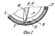
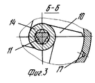
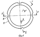
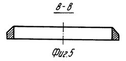
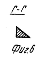
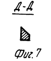
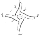
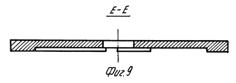
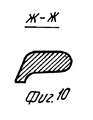
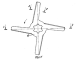
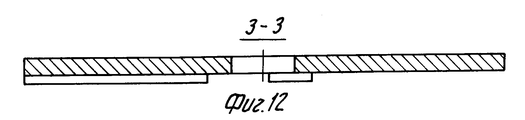
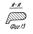
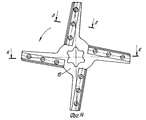
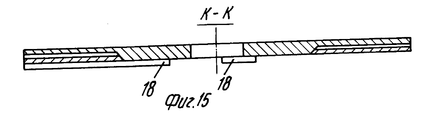
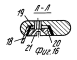
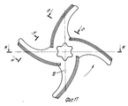
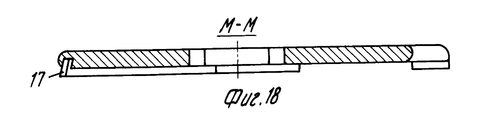
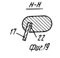
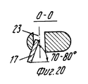
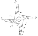
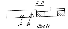
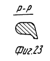
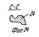
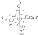
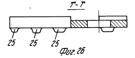
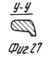
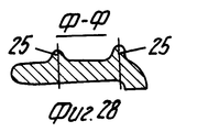
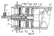
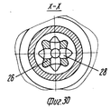
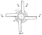
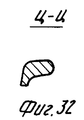
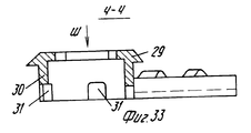
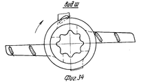
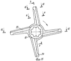
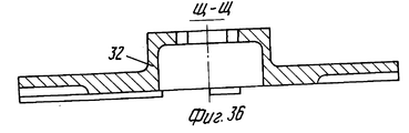
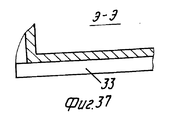
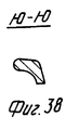
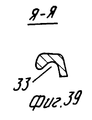
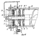
На фиг. 1 показан продольный разрез режущего узла волчка с периферийной выгрузкой улавливаемых включений; на фиг. 2 поперечный разрез по А-А изображенного на фиг. 1 режущего узла волчка; на фиг. 3 поперечный разрез по Б-Б изображенного на фиг. 1 режущего узла; на фиг. 4 вид спереди на разделительное кольцо 6, размещенное перед расположенной на выходе режущего узла режущей парой; на фиг. 5 сечение по В-В разделительного кольца; на фиг. 6 сечение по Г-Г разделительного кольца; на фиг. 7 сечение по Д-Д разделительного кольца; на фиг. 8 вид спереди на нож, лопасти которого выполнены криволинейными и имеют у оснований выпуклую режущую часть, далее переходящую в вогнутую; на фиг. 9 разрез по Е-Е изображенного на фиг. 8 ножа; на фиг. 10 сечение по Ж-Ж изображенного на фиг. 8 ножа; на фиг. 11 - вид спереди на нож с прямыми отогнутыми назад лопастями; на фиг. 12 разрез по З-З изображенного на фиг. 11 ножа; на фиг. 13 сечение по И-И изображенного на фиг. 11 ножа; на фиг. 14 вид спереди на нож со съемными режущими пластинами, закрепленными в продольных пазах его прямых лопастей; на фиг. 15 разрез по К-К изображенного на фиг. 14 ножа; на фиг. 16 сечение по Л-Л изображенного на фиг. 14 ножа; на фиг. 17 вид спереди на нож, в криволинейных пазах лопастей которого закреплены упруго деформированные съемные режущие пластины; на фиг. 18 разрез по М-М изображенного на фиг. 17 ножа; на фиг. 19 сечение по Н-Н изображенного на фиг. 17 ножа; на фиг. 20 - сечение по О-О изображенного на фиг. 17 ножа; на фиг. 21 вид сзади на нож с прямыми лопастями, на тыльных сторонах которых выполнены расположенные по дугам канавки; на фиг. 22 разрез по П-П изображенного на фиг. 21 ножа; на фиг. 23 сечение по Р-Р изображенного на фиг. 21 ножа; на фиг. 24 сечение по С-С изображенного на фиг. 21 ножа; на фиг. 25 вид сзади на нож с прямыми лопастями, на тыльных сторонах которых выполнены расположенные по дугам гребни; на фиг. 26 разрез по Т-Т изображенного на фиг. 25 ножа; на фиг. 27 сечение по У-У изображенного на фиг. 25 ножа; на фиг. 28 сечение по Ф-Ф изображенного на фиг. 26 ножа; на фиг. 29 продольный разрез режущего узла волчка с осевой выгрузкой улавливаемых кусочков включений; на фиг. 30 разрез по Х-Х изображенного на фиг. 29 режущего узла волчка; на фиг. 31 вид спереди на нож с разделительным кольцом, выполненным на втулке ступицы; на фиг. 32 - разрез по Ц-Ц изображенного на фиг. 31 ножа; на фиг. 33 разрез по Ч-Ч изображенного на фиг. 31 ножа; на фиг. 34 вид по стрелке Ш на нож, показанный на фиг. 33; на фиг. 35 вид спереди на нож с продольными пазами в лопастях, соединенных со ступицей посредством втулки; на фиг. 36 разрез по Щ-Щ изображенного на фиг. 35 ножа; на фиг. 38 сечение по Ю-Ю изображенного на фиг. 35 ножа; на фиг. 39 сечение по Я-Я изображенного на фиг. 35 ножа; на фиг. 40 вид на режущий узел волка с размещенными в чехлах термопарами или термометрами сопротивления. In FIG. 1 shows a longitudinal section through a cutting unit of a top with peripheral discharge of trapped inclusions; in FIG. 2 is a cross-section along AA shown in FIG. 1 cutting node of the top; in FIG. 3 is a cross-sectional view along BB shown in FIG. 1 cutting unit; in FIG. 4 is a front view of a dividing
Изображенный на фиг. 1-3 режущий узел волчка с периферийной выгрузкой улавливаемых кусочков твердых включений снабжен входящими в систему разгрузки включений задвижной 1 и патрубком 2, который соединен с полостью отводящего канала 3 в стенке горловины корпуса 4. В полости горловины корпуса 4 размещены набор режущего инструмента и прижимная втулка 5, через которую накидной гайкой 6, навинчиваемой на горловину корпуса 4, сдавливают набор режущего инструмента. Режущий инструмент включает приемную решетку 7, промежуточную решетку 8, расположенную на выходе режущего узла волчка решетку 9, а также примыкающие к лицевой стороне приемной решетки 7, к обеим сторонам промежуточной решетки 8 и к тыльной стороне расположенной на выходе режущего узла волчка решетки 9 односторонние ножи, тыльные стороны которых имеют обтекаемую форму. Решетки 7 9 выполнены в виде круговых колец с отверстиями для прохода измельчаемого продукта, при этом проходное сечение этих отверстий уменьшается по ходу движения сырья. Решетки 7 9, к которым примыкают односторонние ножи 10, имеют центральные отверстия, сквозь которые проходит хвостовик 11 подающего шнека 12. Решетки 7 9 выполнены неподвижными, посредством шпонки 13 они закреплены в горловине корпуса 4. Между ножами 10, насаженными на хвостовик 11 для совместного с ним вращения, размещены распорные втулки 14, передающие создаваемое накидной гайкой 6 усилие, необходимое для прижатия режущих кромок ножей 10 к рабочим поверхностям решеток 7 9. Отверстия в решетке 9 для прохода измельченного продукта должны иметь сравнительно небольшой диаметр с тем, чтобы под действием развиваемого шнеком 12 давления в них можно было бы вдавливать только лишь мягкие ткани кусочков измельчаемого сырья, но не относительно твердые хрящей и сухожилий. В горловине корпуса 4 перед ножом 10, примыкающим к расположенной на выходе режущего узла волчка решетке 9, установлено разделительное кольцо 15, передняя поверхность которого совместно с внутренней поверхностью горловины корпуса 4 и тыльной стороной решетки 9 образует открытую изнутри накопительную камеру, связанную с полостью отводящего канала 3 в стенке горловины корпуса 4. Depicted in FIG. 1-3 the cutting unit of the top with the peripheral unloading of the captured pieces of solid inclusions is equipped with a sliding 1 and
По одному из вариантов выполнения режущего узла волчка в разделительном кольце 15 предусмотрены расположенные по его периферии продольные пазы 16 (фиг. 4-7). По другому варианту разделительное кольцо выполнено сплошным, но в стенке горловины корпуса 4 предусмотрены перепускные каналы 17, связывающие накопительную камеру с позади по ходу движения сырья расположенным пространством полости горловины корпуса 4. Односторонние ножи 10 могут иметь криволинейные лопасти. По одному из вариантов выполнения лопасти ножей изогнуты так, что они, будучи выпуклыми у оснований лопастей, имеют точки перегиба, в которых направление выпуклостей меняется на противоположное (фиг. 11-13). В режущем узле волчка могут применяться ножи с прямыми лопастями, снабженными съемными режущими пластинами 18 (фиг. 14-16), закрепленными в трапецеидальных пазах 19. Для крепления режущих пластин 18 предусмотрены прижимные планки 20 и винты 21 с потайными головками. Для повышения надежности крепления съемных режущих пластин 18 поверхности пазов лопастей ножа 10 и примыкающие к ним поверхности режущих пластин 18, а также поверхности прижимных планок 20 выполнены рифленными (не показано), а между режущими пластинами и примыкающими к ним поверхностями лопастей ножа и прижимных планок в этом случае могут быть размещены эластичные прокладки (на фиг. 15 прокладки показаны жирными линиями). According to one embodiment of the cutting unit of the top in the dividing
Посадочные отверстия с ступицах ножей 10 могут иметь форму шестиконечной звезды со скругленными углами (фиг. 8, 11 и 14). В этом случае хвостовик 11 вала подающего шнека 12 должен быть выполнен в виде трехгранной призмы со скругленными углами (фиг. 3). Такая форма посадочных отверстий ступиц ножей 10 и хвостовика 12 позволяет изменять взаимное расположение лопастей рядом устанавливаемых ножей. В режущем узле могут быть применены ножи с изогнутыми лопастями, также снабженные съемными режущими пластинами 17 (фиг. 17-20). В этом случае в лопастях ножей должны быть выполнены криволинейные пазы 22, наклоненные в плоскости резания под углом 70-80o. В этих пазах размещаются упругодеформированные съемные режущие пластины 17, удерживаемые в лопастях за счет возникающих сил трения. Для выбивания изношенных режущих пластин 17 в лопастях ножей предусмотрены поперечные отверстия 23 (фиг. 20). В режущем узле волчка могут быть применены ножи 10 с прямыми лопастями, на тыльных сторонах которых выполнены расположенные по дугам канавки 24 (фиг. 21-24) или гребни 25 (фиг. 25-28).Landing holes with the hubs of the
Предложенный способ измельчения мяса может быть осуществлен и в режущем узле волчка, выполненном по другому варианту, в котором предусмотрено осевое расположение патрубка для выгрузки кусочков включений. И в этом случае накидная гайка 6 через прижимную втулку 5 сдавливает набор режущего инструмента (фиг. 29, 30). Однако здесь хвостовик 26 подающего шнека 12 должен быть полым и иметь приемные 27 и перепускные 28 отверстия. Посадочные отверстия в ступицах ножей 10, насаженных на полый хвостовик 26, могут быть выполнены в виде восьмиконечных звезд со скругленными углами (фиг. 31, 34 и 35), а хвостовик 26 подающего шнека 12 должен иметь вид четырехгранного стержня со скругленными углами и изогнутыми боковыми гранями, причем вогнутости граней должны быть направлены наружу вписанного круга (фиг. 30). Ступица ножа 10, примыкающего к тыльной стороне расположенной на выходе режущего узла волчка решетки 9, снабжена разделительным кольцом 29, а лопасти этого ножа со ступицей связаны посредством втулки 20, в которой предусмотрены пазы 31 (фиг. 29-33), расположенные у режущих кромок лопастей. Лицевая сторона разделительного кольца 29, наружная поверхность втулки 30 и тыльная сторона расположенной на выходе режущего узла решетки 9 образуют открытую снаружи накопительную камеру, связанную с полостью хвостовика 26 подающего шнека 12 посредством пазов 31, полости втулки 30, а также приемных отверстий 27 (фиг. 29). К лицевой стороне промежуточной решетки 8 примыкает нож 10, лопасти которого со ступицей также связаны посредством втулки 32 (фиг. 35-39). Лопасти этого ножа и стенка втулки 32 выполнены с пазами 33, которые совместно с поверхностью лицевой стороны решетки 8 образуют перепускные каналы. Этот нож установлен так, что втулка его ступицы 32 охватывает перепускные отверстия 28 полого хвостовика 26 подающего шнека 12. The proposed method of meat grinding can be carried out in the cutting unit of the top, made in another embodiment, which provides an axial location of the pipe for unloading pieces of inclusions. And in this case, the
На концах лопастей ножа 10, примыкающего к лицевой стороне промежуточной решетки 8, выполнены поперечные пазы 34, которые совместно с поверхностью лицевой стороны промежуточной решетки 8 образуют каналы, связывающие пространство у лицевой стороны этой решетки с расположенной за разделительным кольцом 29 накопительной камерой. Эти пространства сообщаются между собой через перепускные каналы, образованные пазами 32, перепускные отверстия 28, полость хвостовика 26 подающего шнека 12, приемные отверстия 27, полость втулки 20, а также каналы, образованные пазами 31 и тыльной стороной решетки 9. At the ends of the blades of the
Режущий узел волчка может быть оборудован предназначенными для определения степени нагрева мяса в ходе его измельчения и массирования термопарами или термометрами сопротивления, размещенными в чехлах 34 и 35 (фиг. 40). Расположенный перед режущим узлом чехол 34 может быть выполнен поворотным, что необходимо для облегчения сборки разборки режущего узла. The cutting unit of the top can be equipped for determining the degree of heating of meat during its grinding and massaging with thermocouples or resistance thermometers placed in
Для того чтобы можно было осуществлять предложенный способ измельчения мяса с помощью описанных режущих узлов волчков, должно быть обеспечено следующее. Расстояние между торцем подающего шнека 12 и тыльной стороной приемной решетки 7 должно превышать максимально допустимый размер кусков мяса, подлежащих подаче используемым в волчке шнеком 12. Расстояние между тыльными сторонами ножей 10, примыкающих к лицевой стороне приемной решетки 7 и к тыльной стороне промежуточной решетки 8, должно превышать удвоенный максимальный линейный размер кусочков мяса, полученных в ходе осуществления первой стадии измельчения сырья, т. е. прошедших сквозь отверстия в решетке 7, в случае, если лопасти этих ножей расположены напротив друг друга. Если же лопасти ножей 10, примыкающих к обращенным друг к другу рабочим поверхностям решеток 7 и 8, смещены относительно друг друга на какой-то угол (например, 30-60o), то расстояние между ними должно превышать максимальный линейный размер кусочков мяса, прошедших сквозь отверстия в решетке 7. Завершающую стадию массирования мяса в предлагаемых режущих узлах волчков можно осуществлять крупными или мелкими кусочками твердых включений. Величина кусочков хрящей и сухожилий, используемых на завершающей стадии массирования мяса, определяется шагом подающего шнека 12, толщиной приемной решетки 7, диаметром отверстий в решетке 8 и взаимным расположением лопастей ножей 10, примыкающих к лицевой стороне решетки 7 и к обеим сторонам решетки 8.In order to be able to carry out the proposed method of grinding meat using the described cutting nodes of the tops, the following should be provided. The distance between the end of the
Изменяя взаимное расположение лопастей этих ножей путем поворота их ступиц при насаживании на хвостовик 11 (или 26) подающего шнека 12, можно обеспечить такую величину получаемых кусочков включений, которая будет оптимальной для осуществления процесса массирования каждого вида и сорта измельчаемого мяса. В случае, если предложенный способ измельчения мяса осуществляют с использованием волчка с периферийной выгрузкой кусочков включений, то к решетке 9, расположенной на выходе режущего узла волчка, должен примыкать нож, лопасти которого продвигают участвующие в массировании мяса кусочки включений по направлению к стенке горловины корпуса 4. Этого можно достичь, используя ножи, изображенные на фиг. 8 20 и 25-28. При этом к рабочим поверхностям приемной 7 и промежуточной 8 решеток должны примыкать ножи 10, при вращении своими лопастями перемещающие получаемые в ходе предварительного измельчения сырья крупные кусочки включений по направлению к оси горловины корпуса 4. В случае, когда предложенный способ осуществляют с использованием режущего узла волчка с осевой выгрузкой кусочков включений, то к расположенной на выходе режущего узла волчка решетке 9 должен примыкать нож, лопасти которого при его вращении продвигают кусочки включений по направлениям к оси горловины корпуса 4. Такому требованию отвечает нож, изображенный на фиг. 31-34. При этом к рабочим поверхностям решеток 7 и 8 должны примыкать ножи, лопасти которых будут смещать кусочки твердых включений по направлению к стенке горловины корпуса 4. By changing the relative position of the blades of these knives by turning their hubs when fitting the
Предложенный способ измельчения мяса осуществляют следующим образом. The proposed method of grinding meat is as follows.
В приемный бункер волчка (не показан) загружают сырье в виде кусков мяса с включением обрезков хрящей и сухожилий. Размеры загружаемых в волчок кусков мяса определяются конструктивными особенностями примененного подающего шнека 12. Содержание обрезков хрящей и сухожилий в исходном сырье может быть повышено, для чего используют те из них, которые получены в ходе ручной жиловки мяса. В примыкающее к приемной решетке 7 пространство под действием развиваемого шнеком 12 давления куски сырья подают по прямолинейным траекториям. Это становится возможным потому, что любой кусок сырья, примыкающий к решетке 7, не может одновременно находиться в контакте и с торцем вращаемого подающего шнека 12. Вследствие того, что куски сырья сходят с торца вращаемого шнека 12, в кольцевом пространстве между торцем шнека 12 и обращенной к нему поверхностью решетки 7 они оказываются уложенными по винтовым линиям, но вперед перемещаются без вращения. Под действием развиваемого шнеком 12 давления куски сырья вдавливают в отверстия решетки 7. Первую стадию процесса измельчения сырья осуществляют путем отрезания частей кусков сырья, выступающих из отверстий решетки. При этом на части разрезают и мясо, и поступающие с ним хрящи и сухожилия. В процессе разрезания на части кусков сырья участвуют режущие кромки лопастей ножа 10 и острые кромки отверстий примыкающей к нему приемной решетки 7. В пределах цилиндрического пространства, охватывающего зону действия лопастей ножа 10, примыкающего к приемной решетке 7, кусочки сырья, полученные в результате осуществления первой стадии измельчения, перемещают вперед по винтовым линиям, что становится возможным вследствие совместного воздействия лопастей вращаемого ножа 10 и развиваемого шнеком 13 давления. Raw material in the form of pieces of meat with the inclusion of scraps of cartilage and tendons is loaded into the receiving hopper of a top (not shown). The dimensions of the pieces of meat loaded into the top are determined by the design features of the
В пространстве между тыльными сторонами ножей 10, расположенных между обращенных друг к другу сторонами решеток 7 и 8, кусочки сырья перемещают исключительно по прямолинейным траекториям: в пределах этого пространства на кусочки сырья не воздействуют вращаемые детали. Под действием развиваемого шнеком 12 давления кусочки сырья придвигают к промежуточной решетке 8 и вдавливают их в ее отверстия. Размещенные в этих отверстиях части кусочков сырья удерживают от перемещений вплоть до подхода лопастей вращаемого ножа 106, примыкающего к тыльной стороне решетки 8: размещенные в отверстиях решетки 8 части кусочков сырья оказываются сцепленными с этой решеткой, а выступающие с тыльной стороны решетки 8 остатки от этих кусочков сырья оказываются зажатыми между другими кусочками сырья, в свою очередь сцепленными с решеткой 8. При проходах лопастей ножа 10, примыкающего к тыльной стороне промежуточной решетки 8, осуществляют вторую стадию процесса измельчения сырья: размещенные в отверстиях решетки 8 части кусочков сырья отрезают взаимодействующими режущим кромками лопастей этого ножа и острыми кромками отверстий решетки 8. Остающиеся в отверстиях решетки 8 кусочки сырья проталкивают вперед после прохода лопастей ножа 10, когда в эти отверстия вдавливают части других кусочков сырья. Остающиеся после каждого из таких отрезаний у тыльной поверхности решетки 8 части кусочков сырья не могут быть вовлечены во вращательное движение, так как перед ними находятся другие кусочки сырья, сцепленные с решеткой 8. Такие остатки от кусочков сырья оказываются размещенными в клиновидных зазорах, образованных лобовыми поверхностями лопастей одностороннего ножа 10 и расположенными перед ними сцепленными с решеткой 8 кусочками сырья. Под действием надвигающихся лопастей ножа 10 несцепленные с решеткой 8 кусочки сырья выдавливают из клиновидного зазора, т. е. продвигают назад навстречу потоку сырья до тех пор, пока под ними не пройдут лопасти вращаемого ножа. In the space between the rear sides of the
Сразу же после прохода лопастей ножа 10 отодвинутые от решетки 8 кусочки сырья возвращают к ней, так как в это время на них воздействует только лишь развиваемое шнеком 12 давление. В отверстия решетки 8 снова вдавливают ткани кусочков сырья, подготавливая их к очередному отрезанию надвигающимися лопастями вращаемого ножа 10. Так как лопасти ножа 10 наклонены в стороны, противоположные направлению вращения этого ножа, или же лопасти снабжены направляющими канавками или гребнями, кусочки мяса, кусочки хрящей и сухожилий в ходе их встречного с потоком сырья продвижения смещают либо в направлении к стенке горловины корпуса, либо наоборот в направлении к ее оси в зависимости от того, периферийная или осевая выгрузка кусочков включений предусмотрена. В ходе такого встречного с потоком сырья продвижения кусочков сравнительно жестких хрящей и сухожилий осуществляют первый этап массирования мяса путем воздействия на него более грубыми тканями кусочков включений. Первая стадия процесса массирования мяса имеет ограниченный характер, так как, во-первых кусочки мяса еще сравнительно крупны и, во-вторых, перед решеткой 8 находится сравнительно немного включений хрящей и сухожилий. Кусочки мяса и кусочки включений при проходах лопастей ножа 10 навстречу потоку сырья перемещают по криволинейным траекториям, а к поверхности решетки 8 их снова подают по прямолинейным траекториям. В целом их продвигают вдоль поверхности решетки 8 по пилообразным траекториям, проекции которых на плоскость резания имеют вид отрезков спиралей. Выходящие из отверстий решетки 8 кусочки мяса и кусочки включений хрящей и сухожилий отрезают взаимодействующими острыми кромками этих отверстий и режущими кромками примыкающего к лицевой стороне решетки 8 вращаемого ножа, осуществляя тем самым третью стадию измельчения сырья. Immediately after the passage of the blades of the
В пределах действия лопастей ножа 10, примыкающего к лицевой стороне решетки 8, кусочки сырья, полученные после осуществления третьей стадии измельчения, вперед продвигают по винтовым линиям, так как на них одновременно воздействуют и лопасти этого вращаемого ножа, и развиваемое шнеком 12 давление. За пределами действия лопастей ножа 10, примыкающего к лицевой стороне решетки 8, кусочки сырья вперед по ходу движения сырья подают исключительно по прямолинейным траекториям. Под действием развиваемого шнеком 12 давления ткани мяса, в том числе и сросшиеся с хрящами и сухожилиями, вдавливают в отверстия решетки 9, где их удерживают от перемещений вплоть до подхода лопастей примыкающего к ней вращаемого ножа 10. При проходах лопастей ножа 10 взаимодействующими острыми кромками отверстий решетки 8 и режущими кромками его лопастей отрезают мягкие ткани, вдавленные в отверстия, осуществляя тем самым четвертую, заключительную стадию измельчения мяса. Ткани кусочков включений хрящей и сухожилий не могут быть вдавлены в отверстия решетки 9, имеющие сравнительно небольшой диаметр для этого просто не хватает развиваемого шнеком 12 давления. Поэтому кусочки хрящей и сухожилий в ходе осуществления четвертой, заключительной стадии измельчения, не могут быть разрезаны на части. Остающиеся у поверхности решетки 9 кусочки включений хрящей и сухожилий, а также отрезанные от размещенных в ее отверстиях слоев части кусочков мяса оказываются размещенными в клиновидных зазорах между надвигающимися лобовыми сторонами лопастей вращаемого ножа 10 и впереди, по ходу вращения ножа, расположенными кусочками мяса, сцепленными с этой решеткой. Within the limits of the action of the blades of the
Находящиеся в этих клиновидных зазорах кусочки сырья при проходах лопастей вращаемого ножа 10, входящего в состав расположенной на выходе режущего узла режущей пары, вынуждены перемещаться назад навстречу потоку сырья до тех пор, пока они не будут смещены на расстояние, соответствующее толщине лопастей этого ножа. После прохода лопастей ножа 10 под отодвинутыми от решетки 9 кусочками сырья их снова возвращают к поверхности этой решетки и под действием развиваемого шнеком 12 давления мягкие ткани опять вдавливают в ее отверстия. В целом кусочки сырья при проходах лопастей последнего ножа 10 продвигают встречно-возвратно по пилообразным траекториям, проекции которых на плоскость резания представляют собой отрезки спиралей. Кусочки хрящей и сухожилий могут проталкиваться лопастями вращаемого ножа по поверхности решетки 9 на незначительные расстояния, а также могут быть повернутыми вокруг их собственных осей. В ходе таких продвижений и поворотов острыми кромками отверстий решетки 9 соскабливают остатки мягких тканей с их поверхности. The pieces of raw materials located in these wedge-shaped gaps during the passage of the blades of the
Боковое смещение участвующих в пилообразном движении кусочков сырья имеет место вследствие того, что лопасти примыкающего к решетке 9 вращаемого ножа 10 выполнены криволинейными либо прямыми, но скошенными назад, либо прямыми, но имеющими на тыльных сторонах расположенные по дугам канавки или гребни. Кусочки мяса могут совершать лишь несколько встречно-возвратных продвижений: ведь после каждого такого продвижения следует отрезание от них вдавливаемых в отверстия решетки 9 слоев, так что вскоре каждый кусочек мяса измельчается без остатка. Что же касается кусочков хрящей и сухожилий, то их в ходе осуществления четвертой стадии измельчения мяса не разрезают на части, а лишь передвигают по пилообразным траекториям вдоль поверхности решетки 9 до тех пор, пока они не достигнут зоны действия разделительного кольца 15 (фиг. 1) или 29 (фиг. 29). В ходе каждого из встречно-возвратных перемещений кусочков хрящей и сухожилий в потоке подаваемого к решетке 9 мяса осуществляют второй этап его массирования путем воздействия относительно твердыми тканями включений на ткани мяса. Lateral displacement of the pieces of raw materials involved in the sawtooth movement takes place due to the fact that the blades of the
При этом ткани мяса массируют на всю глубину: подвергнутые воздействию слои срезают в ходе осуществления четвертой стадии измельчения, отрывая тем самым для массирования глубинные слои. Использованными в процессе второго этапа массирования мяса кусочками хрящей и сухожилий заполняют накопительную камеру, образованную у разделительного кольца 15 (или 29), создавая в ней подвижный запорный слой, составленный в основном из кусочков включений, поступающих в отводящий канал 3 и в перепускные каналы 17 (фиг. 1-3), либо в пазы 16 разделительного кольца 15 (фиг. 4-6), либо в полость хвостовика 26 подающего шнека 12, куда их подают после предварительного заполнения полости втулки 30. Для заполнения кусочками включений всех этих полостей в начале работы волчка прикрывают задвижку 1 почти полностью, оставив в ней небольшую щель. В таком положении задвижку 1 оставляют до тех пор, пока из разгрузочного патрубка не перестанет выходить измельченное мясо, которое в этом случае будет отсечено созданным у разделительного кольца 15 (или 29) запорным слоем включений. Кусочки включений хрящей и сухожилий в пределах кольцевого запорного слоя находятся в постоянном движении: они либо перемешиваются концами лопастей ножа 10 (в случае использования режущего узла, изображенного на фиг. 1), либо вращаются совместно с разделительным кольцом 29 и втулкой 30 ступицы ножа 10, примыкающего к решетке 9 (в случае использования режущего узла, на фиг. 29). После заполнения кусочками хрящей и сухожилий полости накопительной камеры и полостей системы их выгрузки обеспечивают накопление их в виде циркулирующего в режущем узле запаса. В случае использования режущего узла волчка с периферийной выгрузкой кусочков включений находящиеся в запасе кусочки включений перемещают из примыкающего к стенке горловины корпуса 4 пространства накопительной камеры по перепускным каналам 17 и выпускают их в измельчаемое сырье сквозь расположенные на выходе этих каналов перепускные отверстия, а затем вместе с сырьем возвращают их к тыльной стороне решетки 4. At the same time, the meat tissues are massaged to the full depth: the exposed layers are cut off during the fourth grinding stage, thereby tearing off the deep layers for massaging. Pieces of cartilage and tendons used in the process of the second stage of massaging the meat fill the storage chamber formed at the dividing ring 15 (or 29), creating a movable locking layer in it, composed mainly of pieces of inclusions entering the
По другому варианту кусочки хрящей и сухожилий для образования движущегося по замкнутым траекториям запаса перепускают из расположенной у стенки горловины корпуса 4 накопительной камеры по каналам, образованным продольными пазами 16 в разделительном кольце 15 и внутренней поверхностью стенки горловины корпуса 4, а возвращают их к решетке 4 совместно с направляемым на заключительную стадию измельчения сырьем. В том случае, если используют волчок с осевой разгрузкой твердых включений, то для образования движущегося по замкнутым траекториям запаса кусочки хрящей и сухожилий из охватывающей втулку 20 ступицы примыкающего к решетке 9 ножа 10 накопительной камеры подают в полость втулки 30, а затем их перемещают через отверстия 27 в полость хвостовика 26 подающего шнека 12. После заполнения всего объема этой полости кусочки включений выпускают через перепускные отверстия 27 в полость втулки 32 ступицы ножа 10, примыкающего к лицевой стороне промежуточной решетки 8. Из полости втулки 32 кусочки включений по каналам, образованным продольными пазами 33 в лопастях этого ножа и поверхностью решетки 8, а также по каналам, образованным поперечными пазами 34 и поверхностью решетки 8, подают в пространство, примыкающее к тыльной стороне решетки 8, откуда их вместе с кусочками сырья перемещают к тыльной стороне решетки 9. О накоплении достаточного количества кусочков хрящей и сухожилий судят по температуре выгружаемого из волчка измельченного мяса или по температуре выгружаемых из волчка кусочков включений. Сопоставив температуру выгружаемых из волчка продуктов измельчения и температуру загружаемого в волчок сырья, которую измеряют термопарами или термометрами сопротивления, размещенными в чехлах 34 и 35 (фиг. 40), можно судить о степени нагрева сырья вследствие его измельчения и массирования циркулирующими в мясе кусочками хрящей и сухожилий. In another embodiment, pieces of cartilage and tendons to form a reserve moving along closed paths are passed from the storage chamber located near the neck of the
Регулируя положение задвижки 1, добиваются такого ее положения, чтобы из разгрузочного патрубка выходили кусочки включений с незначительными примесями измельчаемого мяса. При этом нельзя допускать перегрева измельченного мяса более, чем на 4-5oC, так как при незначительном его перегреве произойдет коагуляция белка и резко снизится влагоемкость фарша. Перемещаемый в режущем узле волчка по замкнутым траекториям запас кусочков хрящей и сухожилий необходим для устранения нежелательных последствий возможных неравномерностей в подаче с измельчаемым сырьем обрезков хрящей и сухожилий. Наличие циркулирующего по замкнутым траекториям запаса позволяет выровнять условия массирования мяса в ходе осуществления заключительной стадии его измельчения. Подвергнутое второй стадии массирования мясо после завершения заключительного этапа его измельчения продавливают сквозь отверстия решетки 9 и выгружают из режущего узла волчка. Кусочки хрящей и сухожилий из режущего узла через разгрузочный патрубок можно выгружать непрерывным потоком, как это описано выше, или порциями, для чего время от времени открывают задвижку 1.By adjusting the position of the
Измельченное по предлагаемому способу мясо используют для приготовления вареных, варено-копченых, полукопченых или копченых колбасных изделий, а также для приготовления начинок для пирожков, пельменей или для приготовления котлет, рубленых бифштексов и иных продуктов питания. Crushed by the proposed method, the meat is used for cooking boiled, boiled-smoked, half-smoked or smoked sausages, as well as for the preparation of fillings for pies, ravioli or for the preparation of meatballs, chopped steaks and other food products.
Как показали производственные испытания предложенного способа измельчения мяса, приготовленные из подвергнутой такому массированию говядины вареные и полукопченые колбасы, а также сардельки и сосиски получались вкуснее, сочнее и нежнее по сравнению с такими же продуктами, приготовленными из мяса, измельченного обычным способом. As shown by the production tests of the proposed method of meat grinding, cooked and semi-smoked sausages prepared from such massaged beef, as well as sausages and sausages, were tastier, juicier and more tender in comparison with the same products made from meat minced in the usual way.
Claims (17)
Priority Applications (1)
| Application Number | Priority Date | Filing Date | Title |
|---|---|---|---|
| RU93043803/03A RU2082503C1 (en) | 1993-09-07 | 1993-09-07 | Meat mincing process and machine implementing it options |
Applications Claiming Priority (1)
| Application Number | Priority Date | Filing Date | Title |
|---|---|---|---|
| RU93043803/03A RU2082503C1 (en) | 1993-09-07 | 1993-09-07 | Meat mincing process and machine implementing it options |
Publications (2)
| Publication Number | Publication Date |
|---|---|
| RU93043803A RU93043803A (en) | 1995-12-20 |
| RU2082503C1 true RU2082503C1 (en) | 1997-06-27 |
Family
ID=20147179
Family Applications (1)
| Application Number | Title | Priority Date | Filing Date |
|---|---|---|---|
| RU93043803/03A RU2082503C1 (en) | 1993-09-07 | 1993-09-07 | Meat mincing process and machine implementing it options |
Country Status (1)
| Country | Link |
|---|---|
| RU (1) | RU2082503C1 (en) |
Cited By (5)
| Publication number | Priority date | Publication date | Assignee | Title |
|---|---|---|---|---|
| WO2006062441A1 (en) * | 2004-11-24 | 2006-06-15 | Igor Feliksvovich Shlegel | Device for breaking and mixing ductile materials, mainly clay |
| WO2006049532A3 (en) * | 2004-11-05 | 2006-07-27 | Eduard Fedorovich Sirovatsky | Meat processing method, meat hashing method, meat hasher, cutting unit for a meat hasher, hashed meat separator (two variants) and a cutting pair for a meat hasher (three variants) |
| RU2297281C1 (en) * | 2005-09-29 | 2007-04-20 | Федеральное государственное унитарное предприятие "Красноярский машиностроительный завод" (ФГУП "Красмаш") | Food product grinding apparatus |
| RU2435664C1 (en) * | 2010-03-15 | 2011-12-10 | Игорь Феликсович Шлегель | Plastic material grinder |
| EP4395935A1 (en) * | 2021-09-03 | 2024-07-10 | Marel Salmon A/S | Knife, knife set, a grinder with axial and radial separator for removing hard constituents, and a method for grinding food or feed products |
-
1993
- 1993-09-07 RU RU93043803/03A patent/RU2082503C1/en not_active IP Right Cessation
Non-Patent Citations (1)
| Title |
|---|
| Заявка ФРГ N 2656991, кл. B 02 C 18/30, 1978. * |
Cited By (6)
| Publication number | Priority date | Publication date | Assignee | Title |
|---|---|---|---|---|
| WO2006049532A3 (en) * | 2004-11-05 | 2006-07-27 | Eduard Fedorovich Sirovatsky | Meat processing method, meat hashing method, meat hasher, cutting unit for a meat hasher, hashed meat separator (two variants) and a cutting pair for a meat hasher (three variants) |
| WO2006062441A1 (en) * | 2004-11-24 | 2006-06-15 | Igor Feliksvovich Shlegel | Device for breaking and mixing ductile materials, mainly clay |
| RU2297324C2 (en) * | 2004-11-24 | 2007-04-20 | Игорь Феликсович Шлегель | Apparatus for grinding and mixing of plastic materials, preferably clay |
| RU2297281C1 (en) * | 2005-09-29 | 2007-04-20 | Федеральное государственное унитарное предприятие "Красноярский машиностроительный завод" (ФГУП "Красмаш") | Food product grinding apparatus |
| RU2435664C1 (en) * | 2010-03-15 | 2011-12-10 | Игорь Феликсович Шлегель | Plastic material grinder |
| EP4395935A1 (en) * | 2021-09-03 | 2024-07-10 | Marel Salmon A/S | Knife, knife set, a grinder with axial and radial separator for removing hard constituents, and a method for grinding food or feed products |
Similar Documents
| Publication | Publication Date | Title |
|---|---|---|
| US3739994A (en) | Apparatus for producing de-boned meat products | |
| US4025001A (en) | Process and apparatus for the mechanical separation of a combination of meats and bone | |
| US4422582A (en) | Food processing machine | |
| US3741772A (en) | Process for producing de-boned meat products | |
| AU2021286253B2 (en) | Grinder assembly | |
| USRE32060E (en) | Process for producing deboned meat products | |
| US3266542A (en) | Machine for separating fragments of bone, gristle or sinew from comminuted meat | |
| US4685626A (en) | Crushed carcase separation head and machine | |
| JPS6123026B2 (en) | ||
| RU2082503C1 (en) | Meat mincing process and machine implementing it options | |
| USRE31631E (en) | Apparatus for producing de-boned meat products | |
| EP0914208B1 (en) | Outlet plate for a food grinder | |
| US3266543A (en) | Method of producing boneless comminuted meat | |
| Abilmazhinov et al. | Technical characteristics and construction features of meat grinders. | |
| CN106391243B (en) | Mincing machine | |
| RU2086302C1 (en) | Method for reprocessing of bulk frozen meat and crusher for mixture of fresh-killed or cooled and frozen meat | |
| US3471299A (en) | Method for deboning eviscerated whole fowl | |
| JP7490767B2 (en) | Conveying screw for cutting and separating device | |
| JP7487301B2 (en) | Shredding drum for cutting and separating device | |
| RU2087196C1 (en) | Method of fine meat grinding and device for its realization | |
| EA000933B1 (en) | Method of grinding meat and meat grinder | |
| US3529646A (en) | Food comminuting mechanism | |
| JP7342251B2 (en) | Mincing drum for cutting separation device | |
| USRE32050E (en) | Process for de-boning meat or fish | |
| RU93043803A (en) | METHOD OF CUTTING MEAT AND WOLNES FOR ITS IMPLEMENTATION |
Legal Events
| Date | Code | Title | Description |
|---|---|---|---|
| MM4A | The patent is invalid due to non-payment of fees |
Effective date: 20050908 |