RU2076782C1 - Device for pneumatic transportation of powder material in liquefied layer on porous base, determination of porous base choking and method of determination of porous base choking - Google Patents
Device for pneumatic transportation of powder material in liquefied layer on porous base, determination of porous base choking and method of determination of porous base choking Download PDFInfo
- Publication number
- RU2076782C1 RU2076782C1 SU5010397/03A SU5010397A RU2076782C1 RU 2076782 C1 RU2076782 C1 RU 2076782C1 SU 5010397/03 A SU5010397/03 A SU 5010397/03A SU 5010397 A SU5010397 A SU 5010397A RU 2076782 C1 RU2076782 C1 RU 2076782C1
- Authority
- RU
- Russia
- Prior art keywords
- porous base
- column
- liquefied
- liquefaction
- chamber
- Prior art date
Links
Images
Classifications
-
- B—PERFORMING OPERATIONS; TRANSPORTING
- B65—CONVEYING; PACKING; STORING; HANDLING THIN OR FILAMENTARY MATERIAL
- B65G—TRANSPORT OR STORAGE DEVICES, e.g. CONVEYORS FOR LOADING OR TIPPING, SHOP CONVEYOR SYSTEMS OR PNEUMATIC TUBE CONVEYORS
- B65G53/00—Conveying materials in bulk through troughs, pipes or tubes by floating the materials or by flow of gas, liquid or foam
- B65G53/34—Details
- B65G53/66—Use of indicator or control devices, e.g. for controlling gas pressure, for controlling proportions of material and gas, for indicating or preventing jamming of material
-
- B—PERFORMING OPERATIONS; TRANSPORTING
- B03—SEPARATION OF SOLID MATERIALS USING LIQUIDS OR USING PNEUMATIC TABLES OR JIGS; MAGNETIC OR ELECTROSTATIC SEPARATION OF SOLID MATERIALS FROM SOLID MATERIALS OR FLUIDS; SEPARATION BY HIGH-VOLTAGE ELECTRIC FIELDS
- B03B—SEPARATING SOLID MATERIALS USING LIQUIDS OR USING PNEUMATIC TABLES OR JIGS
- B03B4/00—Separating by pneumatic tables or by pneumatic jigs
- B03B4/02—Separating by pneumatic tables or by pneumatic jigs using swinging or shaking tables
-
- B—PERFORMING OPERATIONS; TRANSPORTING
- B03—SEPARATION OF SOLID MATERIALS USING LIQUIDS OR USING PNEUMATIC TABLES OR JIGS; MAGNETIC OR ELECTROSTATIC SEPARATION OF SOLID MATERIALS FROM SOLID MATERIALS OR FLUIDS; SEPARATION BY HIGH-VOLTAGE ELECTRIC FIELDS
- B03B—SEPARATING SOLID MATERIALS USING LIQUIDS OR USING PNEUMATIC TABLES OR JIGS
- B03B4/00—Separating by pneumatic tables or by pneumatic jigs
- B03B4/06—Separating by pneumatic tables or by pneumatic jigs using fixed and inclined tables ; using stationary pneumatic tables, e.g. fluidised beds
-
- B—PERFORMING OPERATIONS; TRANSPORTING
- B65—CONVEYING; PACKING; STORING; HANDLING THIN OR FILAMENTARY MATERIAL
- B65G—TRANSPORT OR STORAGE DEVICES, e.g. CONVEYORS FOR LOADING OR TIPPING, SHOP CONVEYOR SYSTEMS OR PNEUMATIC TUBE CONVEYORS
- B65G53/00—Conveying materials in bulk through troughs, pipes or tubes by floating the materials or by flow of gas, liquid or foam
- B65G53/04—Conveying materials in bulk pneumatically through pipes or tubes; Air slides
- B65G53/16—Gas pressure systems operating with fluidisation of the materials
- B65G53/18—Gas pressure systems operating with fluidisation of the materials through a porous wall
- B65G53/22—Gas pressure systems operating with fluidisation of the materials through a porous wall the systems comprising a reservoir, e.g. a bunker
-
- C—CHEMISTRY; METALLURGY
- C25—ELECTROLYTIC OR ELECTROPHORETIC PROCESSES; APPARATUS THEREFOR
- C25C—PROCESSES FOR THE ELECTROLYTIC PRODUCTION, RECOVERY OR REFINING OF METALS; APPARATUS THEREFOR
- C25C3/00—Electrolytic production, recovery or refining of metals by electrolysis of melts
- C25C3/06—Electrolytic production, recovery or refining of metals by electrolysis of melts of aluminium
- C25C3/14—Devices for feeding or crust breaking
Abstract
Description
Изобретение относится к устройствам, использующим порошкообразный материал в состоянии ожиженного слоя с целью его распределения из емкости, транспортировки или физической обработки-сепарации посторонних тел, смешанных с ним. The invention relates to devices using a powder material in a state of a fluidized bed with the aim of its distribution from the tank, transportation or physical processing-separation of foreign bodies mixed with it.
Известна транспортировка от одного места к другому порошкообразных материалов в состоянии ожижения. Материал называют ожижаемым, если он находится в порошкообразной форме и если его гранулометрия и сцепляемость таковы, что поддуваемый воздух, даже с малой скоростью вызывает разлипаемость частиц между собой и снижение сил внутреннего трения так, что образованная таким образом суспензия ведет себя как однородная жидкость. Такими материалами являются, например, алюминий, цементы и гипсы, летучие шлаки, фторид кальция, наполнители для пластмасс и резины, катализаторы, угольная пыль, сульфаты и фосфаты, металлические порошки, порошкообразные пластические материалы, продукты питания, такие как крахмалы, порошкообразные молоко и мука, и т.д. Known transportation from one place to another of powdered materials in a state of liquefaction. A material is called fluidizable if it is in powder form and if its granulometry and adhesion are such that the blown air, even at a low speed, causes the particles to stick together and reduce the forces of internal friction so that the suspension thus formed behaves like a homogeneous liquid. Such materials are, for example, aluminum, cements and gypsum, fly ash, calcium fluoride, fillers for plastics and rubber, catalysts, coal dust, sulfates and phosphates, metal powders, powdered plastic materials, food products such as starches, powdered milk and flour, etc.
Предшествующий уровень техники представлен следующими тремя патентами того же заявителя. The prior art is represented by the following three patents of the same applicant.
Французский патент N 2575734 описывает устройство, обеспечивающее регулирование расхода ожижаемого материала типа алюминия. French patent N 2575734 describes a device for controlling the flow of fluidized material such as aluminum.
Французский патент N 2575680 описывает устройство, обеспечивающее возможность отсепарировать в некотором продукте, состоящем из мелких ожижаемых частиц, скопления слипшихся частиц, не пригодных для ожижения. French patent N 2575680 describes a device that allows the separation in some product, consisting of small fluidizable particles, clusters of sticky particles, not suitable for liquefaction.
Французский патент N 2391136 описывает способ и устройство для автоматического регулирования расхода в системе транспортировки в ожиженном слое без применения механических элементов. French patent No. 2391136 describes a method and apparatus for automatically controlling the flow rate in a fluidized bed transportation system without the use of mechanical elements.
Устройство объект изобретения может применяться с каждым из указанных выше устройств и способов. The device object of the invention can be used with each of the above devices and methods.
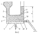
Устройство, описанное во французском патенте N 2575734, имеет (фиг.1) загрузочный бункер 1, наполненный алюминием, связанный с рабочей камерой 2 колонной питания 3, примыкающей со стороны 7А рабочей камеры (слева на фиг. 1); рабочую камеру 2, которая имеет в нижней части 2В ожижающее пористое основание 4 и подвод 5 ожижающего газа при постоянном и регулируемом давлении, в верхней части А2, на конце 7В, противоположном концу колонны питания, колонну 6 уравновешивания и дегазации, на концевой поверхности 7В, соответствующей колонне уравновешивания, и непосредственно над пористым основанием 4, выходное отверстие 8 ожиженного порошкообразного материала. The device described in French patent N 2575734 has (Fig. 1) a
В отсутствии ожижающего газа порошкообразный материал, который хранится в бункере 1, опускается в рабочую камеру 2, формируя естественный откос 10, угол которого с пористым основанием ожижения зависит от природы и физического состояния порошкообразного материала. In the absence of a fluidizing gas, the powdery material that is stored in the
Когда подают ожиженный газ, отверстие 8 при этом закрыто, по каналу 5 и средству регулирования 12 через пористое основание 4 ожижаемый материал начинает ожижаться; он быстро заполняет верхнюю часть рабочей камеры, затем поднимается понемногу в колонну уравновешивания до некоторой высоты h (фиг. 2), которая является функцией ожижающего давления Рf и средней плотности ожижаемого материала в колонне уравновешивания 6. Расчет показывает, а эксперимент подтверждает, что когда система находится в равновесии, при заданных ожижаемом материале и диаметре отверстия 8 расход материала является исключительно функцией давления газа ожижения, что обеспечивает удобное средство регулирования этого расхода.When liquefied gas is supplied, the
В действительности давление ожижения Рf уравновешено гидростатическим давлением, обусловленным высотой h ожиженного слоя в колонне уравновешивания, увеличенном на потери давления в пористом основании. Взаимно однозначное соотношение между давлением ожижения Рf и расходом материала предполагает, что потери давления в пористом основании не изменяются, т.е. это основание не закупоривается. Это имеет место, когда речь идет об идеально чистом материале и однородной гранулометрии, образующей единую ожижаемую фазу. Но если распределяемый материал состоит из двух твердых фаз, одна из которых имеет тенденцию к осаждению в условиях ожижения, эта фаза, осажденная на пористом основании поднимает потери давления через одну стенку. Это приводит при постоянном давлении ожижения к уменьшению высоты h ожижаемого материала в колонне уравновешивания и, следовательно, расхода через отверстие 8. Эта проблема возникает, в частности, в двух случаях:
со свежим глиноземом, который содержит тяжелые частицы жаростойких кирпичей, называемых "песками", которые подмешиваются к глинозему в процессе кальцинации;
в системах питания ванн электролиза алюминия, где рециклируют глинозем, который был использован для улавливания фторированных газов, выходящих из ванн. Этот глинозем с уловленными продуктами стремится сформировать компактные агломераты, называемые в терминах специальности "окалиновой", которые осаждаются на пористой стенке.In fact, the fluidization pressure P f is balanced by hydrostatic pressure due to the height h of the fluidized bed in the equilibration column, increased by pressure loss in the porous base. A one-to-one relationship between the fluidization pressure P f and the material flow rate suggests that the pressure loss in the porous base does not change, i.e. this base is not clogged. This is the case when it comes to perfectly pure material and uniform particle size distribution, forming a single fluidized phase. But if the material to be distributed consists of two solid phases, one of which tends to precipitate under liquefaction conditions, this phase deposited on a porous base raises the pressure loss through one wall. This leads at a constant liquefaction pressure to a decrease in the height h of the liquefied material in the balancing column and, consequently, the flow rate through the
with fresh alumina, which contains heavy particles of heat-resistant bricks called “sands” that are mixed with alumina during calcination;
in aluminum electrolysis bath supply systems, where alumina is recycled, which was used to trap fluorinated gases leaving the baths. This alumina with trapped products tends to form compact agglomerates, called in terms of the specialty “scale,” which are deposited on the porous wall.
Цель изобретения предложить средство для непрерывного наблюдения за степенью забивания пористого основания с тем, чтобы вовремя вмешаться для очистки. The purpose of the invention to provide a tool for continuous monitoring of the degree of clogging of the porous base in order to intervene in time for cleaning.
Предлагаемое рещение проблемы поясняется фиг.3-5. A suggested solution to the problem is illustrated in FIGS. 3-5.
Существует следующее соотношение между различными величинами, действующими на ожижение. The following relationship exists between the various quantities acting on liquefaction.
Давление ожидания Рf равно
Pf Pc + d • h,
где Pc потеря давления через пористое основание;
d плотность порошкообразного материала в ожиженном состоянии;
h высота порошкообразного материала в колонне уравновешивания.The waiting pressure P f equal
P f P c + d • h,
where P c pressure loss through the porous base;
d the density of the powdered material in a fluidized state;
h the height of the powdery material in the balancing column.
С другой стороны, P k•v, где k коэффициент потери давления в пористом основании;
v скорость воздуха через пористое основание.On the other hand, P k • v, where k is the coefficient of pressure loss in the porous base;
v air velocity through a porous base.
В обычных промышленных условиях таких систем скорость потока воздуха ожижения практически всегда достаточно мала, поэтому режим течения - ламинарный и потери давления через пористое основание пропорциональные скорости. Under normal industrial conditions of such systems, the liquefied air flow rate is almost always quite small, therefore the flow regime is laminar and the pressure loss through the porous base is proportional to the velocity.
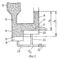
В ходе создания изобретения было обнаружено, что "пески" вследствие их непригодности для ожижения осаждаются на участке пористого основания, расположенном непосредственно или вблизи колонны питания 3. На основе этого разработано устройство, показанное в вертикальном сечении на фиг.3, на которой видны загрузочный бункер 13, связанный с рабочей камерой 14 каналом питания 15, колонна уравновешивания 16 и выходное отверстие для порошкообразного материала 17. Рабочая камера прямоугольного горизонтального сечения дана в вертикальном сечении слева и справа на фигуре. During the development of the invention, it was found that “sands”, due to their unsuitability for liquefaction, are deposited on a porous base site located directly or near the
Слева на фигуре со стороны канала питания первая часть камеры ожижения 18 и пористое основание 19 находятся на уровне ниже уровня второй части камеры ожижения 20 и пористого основания 21 участка рабочей камеры, расположенного справа на фигуре со стороны колонны уравновешивания и выходного отверстия 17. Две части ожижения 18 и 20 запитываются общим каналом 22, разделяющимся на две ветви 23 и 24. On the left side of the figure, on the side of the feed channel, the first part of the fluidization chamber 18 and the
В начале работы, когда впускают газ ожижения, давления уравновешиваются следующим образом. At the beginning of the work, when the fluidization gas is admitted, the pressures are balanced as follows.
Давление ожижения в первой части камеры ожижения ![]()
![]()
где ![]()
![]()
![]()
Where ![]()
Аналогично давление ожижения во второй части камеры ожижения ![]()
![]()
Следовательно, имеет место дифференциальное давление
![]()
Или ![]()
Поскольку части пористого основания 19 и 21 идентичны, и если эти две части пористого основания остаются чистыми и лишенными "песка" или "окалины", то k1 k2.Similarly, the fluidization pressure in the second part of the fluidization chamber ![]()
![]()
Therefore, there is a differential pressure
![]()
Or ![]()
Since the parts of the
Наоборот, с момента, когда "песок" или "окалина" осадились на части пористого основания 19, потеря давления на этой части 19 растет и становится равной
![]()
где kx переменный коэффициент потери давления, возрастающий с засорением части пористого основания 19.On the contrary, from the moment when "sand" or "scale" was deposited on the part of the
![]()
where k x is a variable pressure loss coefficient that increases with clogging of part of the
Следовательно, окончательно
![]()
Разница h1-h2 зависит исключительно от разницы высот между частями пористого основания двух частей рабочей камеры т.е. от геометрии аппарата.Therefore, finally
![]()
The difference h 1 -h 2 depends solely on the height difference between the parts of the porous base of the two parts of the working chamber i.e. from the geometry of the apparatus.
Кажущаяся плотность также постоянна и зависит лишь от ожижаемого продукта. The apparent density is also constant and depends only on the fluidized product.
Коэффициенты k1 и k2 зависят лишь от характеристик пористого основания. Коэффициент kx растет от 0 с увеличением засорения пористой стенки 19.The coefficients k 1 and k 2 depend only on the characteristics of the porous base. The coefficient k x increases from 0 with increasing clogging of the
С другой стороны, скорости v1 и v2 зависят от условий питания воздухом ожижения. Если обозначить ![]()
![]()
![]()
где ![]()
![]()
![]()
![]()
Where ![]()
![]()
![]()
Коэффициент А зависит от геометрических характеристик канала и пропорционален поверхности части пористого основания S1, но для данной установки постоянен. ![]()
![]()
Coefficient A depends on the geometric characteristics of the channel and is proportional to the surface of the part of the porous base S 1 , but is constant for this installation.
Решение системы приводит к уравнению второй степени, которое позволяет определить v1. Окончательно
![]()
Таким же образом можно рассчитать v2, решая систему:

где ![]()
![]()
In the same way, v 2 can be calculated by solving the system:
Where ![]()
Окончательно

Важно отметить
а) как меняется разница давления ![]()
в) как меняется скорость v1 через основание 19 в зависимости от степени засорения этого основания;
а) Подставив значения v1 и v2 и выражение ![]()
![]()
постоянного члена: d•(h1- h2), который является функцией геометрии аппарата, умноженной на высоту h1 h2;
члена: (k1 + kx/ • v1, который зависит
от некоторого числа констант, связанных с конструкцией аппарата;
регулировочного давления Pfo;
коэффициента Kx степени загрязнения пористого основания 19, на котором осаждается "песок" или "окалина";
члена: k2 • v2, который зависит от констант, связанных с конструкцией аппарата, и регулировочного давления ![]()
It is important to note
a) how the pressure difference changes ![]()
c) how the speed v 1 changes through the base 19 depending on the degree of clogging of this base;
a) Substituting the values of v 1 and v 2 and the expression ![]()
![]()
constant term: d • (h 1 - h 2 ), which is a function of the geometry of the apparatus multiplied by the height h 1 h 2 ;
member: (k 1 + k x / • v 1 , which depends
from a number of constants associated with the design of the apparatus;
adjusting pressure P fo ;
coefficient K x of the degree of contamination of the
member: k 2 • v 2 , which depends on the constants associated with the design of the apparatus and the control pressure ![]()
Анализ функции ![]()
![]()
в) анализ функции v1 g(kx) показывает, что эта функция стремится к 0, если kx растет и устремляется к бесконечности. Итак, уравнения, записанные выше, применимы лишь, если v1 существенно превышает значение vmf, минимальной скорости ожижения для рассматриваемого материала.c) analysis of the function v 1 g (k x ) shows that this function tends to 0 if k x grows and tends to infinity. So, the equations written above are applicable only if v 1 significantly exceeds the value of v mf , the minimum fluidization rate for the material under consideration.
Таким образом, постоянное измерение и возможная регистрация дифференциального давления ![]()
следить за эволюцией загрязнения пористого основания в зоне осаждения "песка" и "окалины";
автоматически или вручную подключать очистку аппарата путем фиксации значения ![]()
![]()
monitor the evolution of contamination of the porous base in the zone of deposition of "sand" and "scale";
automatically or manually connect the cleaning device by fixing the value ![]()
Пример 1. Система питания ванны для электролиза алюминия выполнена в соответствии с изобретением. Example 1. The bath power system for aluminum electrolysis is made in accordance with the invention.
Первая часть рабочей камеры, распложенная под каналом питания, имеет длину, измеренную в направлении плоскости фиг.3, примерно 26 см, а ширину приблизительно 20 см. Вторая часть рабочей камеры имеет длину приблизительно 16 см и ширину 20 см. Пористое основание первой части располагается в 10 см над пористым основанием во второй части. The first part of the working chamber, located under the feed channel, has a length, measured in the direction of the plane of FIG. 3, of about 26 cm and a width of about 20 cm. The second part of the working chamber has a length of about 16 cm and a width of 20 cm. The porous base of the first part is located 10 cm above the porous base in the second part.
В начале работы, когда пористое основание свободно от закупорки, отмечены следующие параметры:
Давление ожижения ![]()
Давление ожижения ![]()
Высота слоя в колонне уравновешивания h 58 см.At the beginning of the work, when the porous base is free from clogging, the following parameters are noted:
Liquefaction pressure ![]()
Liquefaction pressure ![]()
The height of the layer in the column of balancing h 58 cm
При диаметре выходного отверстия 19 мм был получен расход глинозема 25000 г/мин. With an outlet diameter of 19 mm, an alumina flow rate of 25,000 g / min was obtained.
Разница давлений ожижения, равная первоначально 50 мм вод. ст. (490 Па), в процессе работы постепенно растет; она непрерывно регистрируется и, когда она достигает значения 90 мм вод. ст. (883 Па), установка остановлена и приступают к раскупорке пористого основания. The difference in pressure of the liquefaction, initially equal to 50 mm of water. Art. (490 Pa), in the process of work gradually grows; it is continuously recorded and when it reaches a value of 90 mm of water. Art. (883 Pa), the installation is stopped and begin to open the porous base.
Этот пример дан исключительно в качестве иллюстрации. This example is given as an illustration only.
Размеры частей пористого основания, первой и второй частей пористого основания разница между этими частями зависят от природы продаваемого продукта, содержания в нем песка или окалины, расхода, который необходимо обеспечить и допустимым временем между двумя очистками. The sizes of the parts of the porous base, the first and second parts of the porous base, the difference between these parts depends on the nature of the product sold, the content of sand or scale in it, the flow rate that must be ensured and the acceptable time between two cleanings.
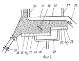
Пример 2. Объект изобретения был применен для устройства по французскому патенту N 2575680. Это применение показано на фиг.4. Example 2. The object of the invention was applied to the device according to French patent N 2575680. This application is shown in figure 4.
Оно позволяет обеспечить сепарацию ожижаемого порошкообразного материала от не ожижаемого материала, который к нему подмешан. Емкость 25, подвешенная с помощью упругих средств (не показаны), состоит из двух частей рабочей камеры 26 и 27, запитываемых газом ожижения двумя ветвями 28 и 29, выходящими из общего канала 31. Две части рабочей камеры разделены пористым основанием на две части 32 и 33, причем камеры 26 и пористое основание 32 со стороны питания материалом располагаются ниже чем камера 27 и пористое основание 33. Верхняя камера имеет питание 34 смесью ожижаемого материала и не ожижаемого материала: слив 35 для эвакуации ожижаемой фазы; система шлюза 36 для эвакуации твердой не ожиженной фазы, осажденной на участке 32 пористого основания; трубка для эвакуации газа ожижения 37; система вибрации, сообщающаяся пористому основанию вибрационное движение в направлении стрелки 38. It allows the separation of fluidizable powder material from non-fluidizable material that is mixed with it. The
В процессе работы частицы не ожижаемого материала осаждаются на пористом основании 32, вызывая рост разницы давлений ![]()
![]()
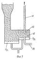
Пример 3. Объект изобретения был применен со способом по французскому патенту N 2391136. Это применение показано на фиг.5. Некоторые характеристики, уже описанные в предшествующих примерах, представлены на этой фигуре: емкость ожижения с нижней частью рабочей камеры и пористое основание с двумя участками, смещенными вертикально, колонна питания порошкообразным продуктом. Устройство включает, кроме того, канал питания газом под давлением 39, заканчивающийся над пористым основанием инжектором 40, и канал, предназначенный для пневматического транспорта 41, снабженный насадком 42, расположенным вертикально над инжектором. Как это было пояснено во французском патенте N 2391136, эта система позволяет автоматически регулировать расход порошкообразного материала. Однако работа может быть возмущена присутствием неожижаемого материала, присоединение системы с двумя уровнями пористого основания и контроль разницы давлений ожижения позволяет детектировать степень закупорки пористого основания и вовремя произвести его очистку. Example 3. The object of the invention was applied with the method according to French patent N 2391136. This application is shown in Fig.5. Some of the characteristics already described in the previous examples are presented in this figure: a liquefaction tank with a lower part of the working chamber and a porous base with two sections vertically displaced, a supply column of a powdered product. The device also includes a gas supply channel under
Claims (5)
Applications Claiming Priority (2)
| Application Number | Priority Date | Filing Date | Title |
|---|---|---|---|
| FR9016572A FR2671061A1 (en) | 1990-12-26 | 1990-12-26 | DEVICE FOR SEPARATING FLUIDIZED BED MATERIAL AND COLDING DETECTION. |
| FR9016572 | 1990-12-26 |
Publications (1)
| Publication Number | Publication Date |
|---|---|
| RU2076782C1 true RU2076782C1 (en) | 1997-04-10 |
Family
ID=9403909
Family Applications (1)
| Application Number | Title | Priority Date | Filing Date |
|---|---|---|---|
| SU5010397/03A RU2076782C1 (en) | 1990-12-26 | 1991-12-25 | Device for pneumatic transportation of powder material in liquefied layer on porous base, determination of porous base choking and method of determination of porous base choking |
Country Status (15)
| Country | Link |
|---|---|
| US (1) | US5299694A (en) |
| EP (1) | EP0493279B1 (en) |
| CN (1) | CN1028741C (en) |
| BR (1) | BR9105491A (en) |
| CA (1) | CA2058381C (en) |
| DE (1) | DE69103617T2 (en) |
| ES (1) | ES2059093T3 (en) |
| FR (1) | FR2671061A1 (en) |
| IS (1) | IS1683B (en) |
| NO (1) | NO305068B1 (en) |
| NZ (1) | NZ241064A (en) |
| RO (1) | RO111260B1 (en) |
| RU (1) | RU2076782C1 (en) |
| YU (1) | YU48081B (en) |
| ZA (1) | ZA9110068B (en) |
Cited By (1)
| Publication number | Priority date | Publication date | Assignee | Title |
|---|---|---|---|---|
| RU173068U1 (en) * | 2016-12-20 | 2017-08-08 | Общество с ограниченной ответственностью "Пневмотранспорт" | DEVICE FOR PNEUMATIC TRANSPORTATION IN PISTON MODE OF LARGE-GRAIN AND BULK MATERIALS FROM THE BUNKER |
Families Citing this family (23)
| Publication number | Priority date | Publication date | Assignee | Title |
|---|---|---|---|---|
| US5526938A (en) * | 1994-10-07 | 1996-06-18 | The Babcock & Wilcox Company | Vertical arrangement fluidized/non-fluidized bed classifier cooler |
| DE59610361D1 (en) * | 1995-09-18 | 2003-05-28 | Elpatronic Ag Bergdietikon | Process for conveying a powdery material by means of an injector |
| US5669509A (en) * | 1996-02-28 | 1997-09-23 | Kerr-Mcgee Chemical Corporation | Dry separation of fine powder from coarse contaminant in a vibrating fluid bed |
| JP2812917B2 (en) * | 1996-04-18 | 1998-10-22 | 川崎重工業株式会社 | Fluidized bed classifier |
| AU3390197A (en) * | 1996-05-29 | 1998-01-07 | Kerr-Mcgee Chemical L.L.C. | Dry separation of fine powder from coarse contaminant in a vibrating fluid bed |
| FR2779136B1 (en) | 1998-06-02 | 2000-07-28 | Pechiney Aluminium | PROCESS FOR CONVEYING HYDROPENSIVE PHASE OF POWDERY MATERIALS APPLICABLE TO BYPASSING OBSTACLES |
| FR2831528B1 (en) * | 2001-10-26 | 2004-01-16 | Pechiney Aluminium | POWDER MATERIAL DISTRIBUTION SYSTEM WITH CONTROLLED WEIGHTS |
| US7593637B2 (en) * | 2002-04-30 | 2009-09-22 | Angela Chiu | Optical transport system architecture for remote terminal connectivity |
| US6977096B2 (en) * | 2002-10-03 | 2005-12-20 | Material Technologies, Inc. | Method of coating surface with tungsten disulfide |
| US20040187979A1 (en) * | 2003-03-31 | 2004-09-30 | Material Technologies, Inc. | Cutting tool body having tungsten disulfide coating and method for accomplishing same |
| US7987613B2 (en) * | 2004-10-12 | 2011-08-02 | Great River Energy | Control system for particulate material drying apparatus and process |
| US8523963B2 (en) * | 2004-10-12 | 2013-09-03 | Great River Energy | Apparatus for heat treatment of particulate materials |
| US7540384B2 (en) * | 2004-10-12 | 2009-06-02 | Great River Energy | Apparatus and method of separating and concentrating organic and/or non-organic material |
| US8062410B2 (en) | 2004-10-12 | 2011-11-22 | Great River Energy | Apparatus and method of enhancing the quality of high-moisture materials and separating and concentrating organic and/or non-organic material contained therein |
| US8579999B2 (en) | 2004-10-12 | 2013-11-12 | Great River Energy | Method of enhancing the quality of high-moisture materials using system heat sources |
| US7275644B2 (en) * | 2004-10-12 | 2007-10-02 | Great River Energy | Apparatus and method of separating and concentrating organic and/or non-organic material |
| FR2918975B1 (en) * | 2007-07-19 | 2009-11-20 | Alcan Int Ltd | PROCESS FOR CONVEYING WITHOUT SEGREGATION OF PULVERULENT MATERIALS |
| FR2952363B1 (en) * | 2009-11-09 | 2011-11-11 | Alcan Int Ltd | POTENTIALLY FLUIDIZING DEVICE FOR CONVEYING PULVERULENT MATERIALS IN HYPERDENSE BED |
| NO338642B1 (en) * | 2014-09-12 | 2016-09-26 | Norsk Hydro As | Apparatus and method for feeding doses of fluidizable materials |
| CN106672632B (en) * | 2015-11-09 | 2019-03-15 | 中联重科股份有限公司 | For the control method of Pneumatic conveyer, equipment, system and engineering machinery |
| EP3181497B1 (en) * | 2015-12-18 | 2019-02-20 | Claudius Peters Projects GmbH | Deflection unit for pneumatic conveying apparatus |
| NO343343B1 (en) * | 2016-11-21 | 2019-02-04 | Norsk Hydro As | Apparatus and method for feeding doses of fluidisable materials |
| CN114007764B (en) * | 2019-06-11 | 2024-03-26 | 系统陶瓷股份公司 | Dispensing apparatus for granular material |
Family Cites Families (21)
| Publication number | Priority date | Publication date | Assignee | Title |
|---|---|---|---|---|
| FR2236758B1 (en) * | 1973-07-02 | 1978-12-29 | Pechiney Aluminium | |
| US3863428A (en) * | 1973-11-14 | 1975-02-04 | Robert L Baxter | Blockage monitor for a cotton picking machine |
| US3986949A (en) * | 1975-07-07 | 1976-10-19 | Duca Mark B Di | Air classifier |
| GB1587201A (en) * | 1976-07-16 | 1981-04-01 | Exxon Research Engineering Co | Utilisation of solid material containing combustible matter |
| SU698876A1 (en) * | 1977-05-05 | 1979-11-25 | Химико-Метуллургический Институт Ан Казахской Сср | Method of monitoring the speed of compact layer of loose material |
| FR2391136A1 (en) * | 1977-05-18 | 1978-12-15 | Pechiney Aluminium | PROCESS FOR SELF-REGULATION OF PNEUMATIC TRANSPORT |
| JPS544478A (en) * | 1977-06-10 | 1979-01-13 | Ishikawajima Harima Heavy Ind Co Ltd | Method of detecting blocked place in refuse vacuum transportation device |
| SU975547A1 (en) * | 1980-12-22 | 1982-11-23 | Центральный Научно-Исследовательский И Проектно-Конструкторский Институт Проходческих Машин И Комплексов Для Угольной,Горной Промышленности И Подземного Строительства | Method of monitoring the working duty of pneumatic transport unit |
| DE3266106D1 (en) * | 1981-03-09 | 1985-10-17 | Macawber Eng Ltd | Conveying apparatus |
| US4908124A (en) * | 1982-09-20 | 1990-03-13 | Combustion Power Company | Method and apparatus for removing foreign objects from fluid bed systems |
| JPS60106720A (en) * | 1983-11-14 | 1985-06-12 | Kobe Steel Ltd | Method of detecting clogging in pulverized material gas-stream conveyor device |
| FR2575680B1 (en) * | 1985-01-08 | 1987-07-03 | Pechiney Aluminium | FLUIDIZED BED DEVICE FOR THE CONTINUOUS SEPARATION OF TWO MIXED SOLID PHASES |
| FR2575734B1 (en) * | 1985-01-08 | 1989-11-17 | Pechiney Aluminium | REGULATED FLOW DISPENSING DEVICE OF A FLUIDISABLE POWDER MATERIAL |
| DE3631182A1 (en) * | 1986-09-12 | 1988-03-24 | Krupp Polysius Ag | Method and device for the continuous pneumatic discharge of material from a pressurised conveying vessel |
| DE3714923A1 (en) * | 1987-05-05 | 1988-12-01 | Waeschle Maschf Gmbh | DEVICE FOR PNEUMATICALLY CONVEYING SCHUETTGUT |
| US4861464A (en) * | 1987-05-29 | 1989-08-29 | State Of Israel, Ministry Of Agriculture | Method and apparatus for separation using fluidized bed |
| JPS6445925A (en) * | 1987-08-17 | 1989-02-20 | Kawasaki Steel Co | Energy recovering method for blast furnace gas |
| US4946044A (en) * | 1988-05-18 | 1990-08-07 | Kennedy Van Saup Corporation | Aeration separator |
| JPH0662216B2 (en) * | 1988-07-23 | 1994-08-17 | 川崎製鉄株式会社 | Blockage detection method in powder mixing and transportation |
| US5071541A (en) * | 1988-09-30 | 1991-12-10 | The Boeing Company | Method and apparatus for sorting a mixture of particles |
| US5048693A (en) * | 1989-06-28 | 1991-09-17 | World Agrosearch, Ltd. | Method and apparatus for sorting articles with small density differences utilizing a flotation stream |
-
1990
- 1990-12-26 FR FR9016572A patent/FR2671061A1/en active Granted
-
1991
- 1991-12-18 BR BR919105491A patent/BR9105491A/en not_active IP Right Cessation
- 1991-12-19 NZ NZ241064A patent/NZ241064A/en unknown
- 1991-12-19 IS IS3796A patent/IS1683B/en unknown
- 1991-12-20 DE DE69103617T patent/DE69103617T2/en not_active Expired - Fee Related
- 1991-12-20 YU YU197191A patent/YU48081B/en unknown
- 1991-12-20 ZA ZA9110068A patent/ZA9110068B/en unknown
- 1991-12-20 NO NO915058A patent/NO305068B1/en unknown
- 1991-12-20 ES ES91420462T patent/ES2059093T3/en not_active Expired - Lifetime
- 1991-12-20 EP EP91420462A patent/EP0493279B1/en not_active Expired - Lifetime
- 1991-12-23 RO RO149027A patent/RO111260B1/en unknown
- 1991-12-23 CA CA002058381A patent/CA2058381C/en not_active Expired - Fee Related
- 1991-12-25 CN CN91111879A patent/CN1028741C/en not_active Expired - Fee Related
- 1991-12-25 RU SU5010397/03A patent/RU2076782C1/en not_active IP Right Cessation
-
1993
- 1993-06-18 US US08/078,065 patent/US5299694A/en not_active Expired - Fee Related
Cited By (1)
| Publication number | Priority date | Publication date | Assignee | Title |
|---|---|---|---|---|
| RU173068U1 (en) * | 2016-12-20 | 2017-08-08 | Общество с ограниченной ответственностью "Пневмотранспорт" | DEVICE FOR PNEUMATIC TRANSPORTATION IN PISTON MODE OF LARGE-GRAIN AND BULK MATERIALS FROM THE BUNKER |
Also Published As
| Publication number | Publication date |
|---|---|
| NO915058D0 (en) | 1991-12-20 |
| CN1028741C (en) | 1995-06-07 |
| FR2671061B1 (en) | 1995-05-12 |
| YU48081B (en) | 1997-01-08 |
| NO915058L (en) | 1992-06-29 |
| NZ241064A (en) | 1994-03-25 |
| DE69103617T2 (en) | 1994-12-22 |
| EP0493279A1 (en) | 1992-07-01 |
| ZA9110068B (en) | 1992-10-28 |
| DE69103617D1 (en) | 1994-09-29 |
| ES2059093T3 (en) | 1994-11-01 |
| NO305068B1 (en) | 1999-03-29 |
| EP0493279B1 (en) | 1994-08-24 |
| RO111260B1 (en) | 1996-08-30 |
| YU197191A (en) | 1995-03-27 |
| BR9105491A (en) | 1992-09-01 |
| CN1062705A (en) | 1992-07-15 |
| IS3796A7 (en) | 1992-06-27 |
| CA2058381C (en) | 1994-05-03 |
| CA2058381A1 (en) | 1992-06-27 |
| US5299694A (en) | 1994-04-05 |
| FR2671061A1 (en) | 1992-07-03 |
| IS1683B (en) | 1998-02-24 |
Similar Documents
| Publication | Publication Date | Title |
|---|---|---|
| RU2076782C1 (en) | Device for pneumatic transportation of powder material in liquefied layer on porous base, determination of porous base choking and method of determination of porous base choking | |
| US9090413B2 (en) | Potential fluidization device for conveying powder materials in a hyperdense bed | |
| US3604758A (en) | Apparatus for the conveyance of cohesive particulate material | |
| CA1264788A (en) | Apparatus and process for pneumatically conveying particulate material | |
| RU2487829C2 (en) | Method of segregation-free transfer of powder materials | |
| EP0187730B1 (en) | Fluidized-bed device for continuously separating two mixed solid phases | |
| US8950570B2 (en) | Passive solids supply system and method for supplying solids | |
| IE58688B1 (en) | Apparatus for distribution at a regulated rate of a fluidisable powdery material | |
| SI8312088A8 (en) | Closed device with possibility of fludisation for pulverised materials horizontal transportation | |
| US3861753A (en) | Method of and apparatus for discharging pulverulent material from silos or the like | |
| US4165133A (en) | Material handling system for wide range of materials and flow rates | |
| JPS61501857A (en) | Equipment that conveys powdery substances in a dense layer | |
| Daous et al. | Modeling solids and gas flow through an L-valve | |
| US4986456A (en) | Flow rate controller and feeder | |
| RU2246357C1 (en) | Separator loading unit | |
| SI9111971A (en) | Device for separating material in fluidic trough and for perception obturation | |
| NL2030096A (en) | DEVICE FOR STORAGE, TRANSPORT AND DOSING OF RAW MATERIALS IN THE FOOD INDUSTRY | |
| WO1986002912A1 (en) | A particulate solid feeding device | |
| JPS6370008A (en) | Growing fluid medium discharge system | |
| SU1133195A1 (en) | Method for pneumatic conveying of bulk materials | |
| GB2616846A (en) | Feedback control loop for pneumatic conveying | |
| Gu et al. | The influence of surcharge level on the flowrate of bulk solids from mass flow bins | |
| Barbosa-Cánovas et al. | Storage | |
| JPH0648206B2 (en) | Constant velocity feeder for moving packed bed | |
| SI8610006A8 (en) | Separating device with controlled quantity of pulverised material which can be fluidised |
Legal Events
| Date | Code | Title | Description |
|---|---|---|---|
| MM4A | The patent is invalid due to non-payment of fees |
Effective date: 20031226 |