RU2069700C1 - Blast furnace air heater and method of its production - Google Patents
Blast furnace air heater and method of its production Download PDFInfo
- Publication number
- RU2069700C1 RU2069700C1 RU9393004438A RU93004438A RU2069700C1 RU 2069700 C1 RU2069700 C1 RU 2069700C1 RU 9393004438 A RU9393004438 A RU 9393004438A RU 93004438 A RU93004438 A RU 93004438A RU 2069700 C1 RU2069700 C1 RU 2069700C1
- Authority
- RU
- Russia
- Prior art keywords
- bricks
- blast furnace
- walls
- connecting elements
- cast
- Prior art date
Links
Images
Classifications
-
- F—MECHANICAL ENGINEERING; LIGHTING; HEATING; WEAPONS; BLASTING
- F27—FURNACES; KILNS; OVENS; RETORTS
- F27D—DETAILS OR ACCESSORIES OF FURNACES, KILNS, OVENS, OR RETORTS, IN SO FAR AS THEY ARE OF KINDS OCCURRING IN MORE THAN ONE KIND OF FURNACE
- F27D1/00—Casings; Linings; Walls; Roofs
- F27D1/04—Casings; Linings; Walls; Roofs characterised by the form, e.g. shape of the bricks or blocks used
-
- C—CHEMISTRY; METALLURGY
- C21—METALLURGY OF IRON
- C21B—MANUFACTURE OF IRON OR STEEL
- C21B9/00—Stoves for heating the blast in blast furnaces
- C21B9/02—Brick hot-blast stoves
- C21B9/06—Linings
-
- F—MECHANICAL ENGINEERING; LIGHTING; HEATING; WEAPONS; BLASTING
- F27—FURNACES; KILNS; OVENS; RETORTS
- F27D—DETAILS OR ACCESSORIES OF FURNACES, KILNS, OVENS, OR RETORTS, IN SO FAR AS THEY ARE OF KINDS OCCURRING IN MORE THAN ONE KIND OF FURNACE
- F27D1/00—Casings; Linings; Walls; Roofs
-
- F—MECHANICAL ENGINEERING; LIGHTING; HEATING; WEAPONS; BLASTING
- F27—FURNACES; KILNS; OVENS; RETORTS
- F27D—DETAILS OR ACCESSORIES OF FURNACES, KILNS, OVENS, OR RETORTS, IN SO FAR AS THEY ARE OF KINDS OCCURRING IN MORE THAN ONE KIND OF FURNACE
- F27D1/00—Casings; Linings; Walls; Roofs
- F27D1/16—Making or repairing linings increasing the durability of linings or breaking away linings
- F27D1/1621—Making linings by using shaped elements, e.g. bricks
-
- F—MECHANICAL ENGINEERING; LIGHTING; HEATING; WEAPONS; BLASTING
- F27—FURNACES; KILNS; OVENS; RETORTS
- F27D—DETAILS OR ACCESSORIES OF FURNACES, KILNS, OVENS, OR RETORTS, IN SO FAR AS THEY ARE OF KINDS OCCURRING IN MORE THAN ONE KIND OF FURNACE
- F27D1/00—Casings; Linings; Walls; Roofs
- F27D2001/0079—Means to assemble at least two parts of a furnace or of any device or accessory associated to its use
-
- F—MECHANICAL ENGINEERING; LIGHTING; HEATING; WEAPONS; BLASTING
- F27—FURNACES; KILNS; OVENS; RETORTS
- F27D—DETAILS OR ACCESSORIES OF FURNACES, KILNS, OVENS, OR RETORTS, IN SO FAR AS THEY ARE OF KINDS OCCURRING IN MORE THAN ONE KIND OF FURNACE
- F27D99/00—Subject matter not provided for in other groups of this subclass
- F27D99/0073—Seals
Abstract
Description
Изобретение касается доменного воздухонагревателя, имеющего жароупорную конструкцию из двух или больше стенок, выполненных главным образом из кирпичей и соединенных вместе соединительными элементами, а также касается способа изготовления такого доменного воздухонагревателя. The invention relates to a blast furnace having a heat-resistant structure of two or more walls, made mainly of bricks and connected together by connecting elements, and also relates to a method of manufacturing such a blast furnace.
Известны доменные воздухонагреватели, которые применяются для нагрева воздуха, вдуваемого в доменную печь. Одна известная конструкция доменного воздухонагревателя состоит из окружающей стенки, внутри которой расположены камера сгорания и камер насадки, причем камеры разделены перегородкой, соединенной с окружающей стенкой на обеих сторонах посредством соединительных элементов. В этом известном доменном воздухонагревателе кирпичи и соединительные элементы выполнены из предварительно формованных, спрессованных и обожженных кирпичей. Эти соединительные элементы в форме кирпичей часто имеют сложную форму, и они служат для образования различных соединений, напримеp, между окружающей стенкой и перегородкой. Поскольку стенки воздвигают перевязку с кирпичной кладкой, то соединительные кирпичи также имеют различные формы для различных слоев, из которых состоит стенка. Для изготовления известного доменного воздухонагревателя соединительные кирпичи изготавливают заранее посредством прессования их в специально сконструированных массивных пресс-формах. Изменение формы различных соединительных кирпичей требует соответствующего изменения пресс-форм, что влечет за собой нежелательные расходы. Фиг. 1А, 1В и 1С служат для иллюстрации применения различных соединительных кирпичей в одном доменном воздухонагревателе; на практике количество составляет свыше 35, причем для их изготовления требуется такое же количество различных пресс-форм. Кроме того, возможность придания определенной формы и конфигурация предварительно изготовленных соединительных кирпичей, которые должны пригоняться так, чтобы они хорошо связывались с кирпичной кладкой, ограничивают возможности конструирования и изготовления известного доменного воздухонагревателя. Known blast furnaces that are used to heat the air blown into the blast furnace. One known design of a blast furnace heater consists of a surrounding wall, inside which a combustion chamber and nozzle chambers are located, the chambers being separated by a partition connected to the surrounding wall on both sides by means of connecting elements. In this well-known blast furnace, bricks and connecting elements are made of pre-molded, pressed and fired bricks. These connecting elements in the form of bricks are often complex in shape and they serve to form various joints, for example, between the surrounding wall and the partition. Since the walls are lined with masonry, the connecting bricks also have different shapes for the different layers of which the wall consists. For the manufacture of a well-known blast furnace heater, connecting bricks are made in advance by pressing them in specially designed massive molds. Changing the shape of various connecting bricks requires a corresponding change in the mold, which entails undesirable costs. FIG. 1A, 1B and 1C are used to illustrate the use of various connecting bricks in one blast furnace; in practice, the amount is over 35, and for their manufacture requires the same number of different molds. In addition, the ability to give a certain shape and configuration of prefabricated connecting bricks, which must be fitted so that they are well connected with the masonry, limit the possibilities of designing and manufacturing a known blast furnace.
Известны конструкция и кирпичная кладка доменных воздухонагревателей (Stahlund Eisen, том 95, (1975), N 17, с. 802 806; Metallugist, том 23, N 1/2, (1979), с. 97, 98). Known design and brickwork of blast furnace air heaters (Stahlund Eisen, Volume 95, (1975), N 17, p. 802 806; Metallugist, Volume 23,
Целью изобретения является создание доменного воздухонагревателя и разработка способа его изготовления, который не имеет упомянутые недостатки. В частности, цель изобретения это создание способа, который исключает необходимость в применении большого количества массивных пресс-форм. The aim of the invention is the creation of a blast furnace and the development of a method for its manufacture, which does not have the mentioned disadvantages. In particular, the purpose of the invention is the creation of a method that eliminates the need for a large number of massive molds.
Согласно изобретению предложен способ изготовления доменного воздухонагревателя, имеющего две жароупорные стенки, соединенные друг с другом встык, заключающийся в возведении двух стенок, состоящих главным образом из кирпичей, и размещении по крайней мере одного литого соединительного элемента в точке соединения стенок. According to the invention, a method for manufacturing a blast furnace air heater having two heat-resistant walls, butt-joined to each other, consisting in the construction of two walls, consisting mainly of bricks, and the placement of at least one molded connecting element at the junction of the walls.
В точке соединенных стенок применяют литые соединительные элементы, расположенные предпочтительно во множестве кладок и/или слоев кирпичей для стенок. Литые соединительные элементы можно изготовить заранее до их размещения в стенках, причем их можно изготовить в относительно легких и простых формах, и они не требуют спекания. Литой соединительный элемент или элементы отливают на месте в точках их расположения между стенками. Это дает преимущество в том, что не требуется предварительного формования в отдельных формах и исключается необходимость в применении большого количества различных форм. Вместо этого может потребоваться опалубка для изготовления простых временных форм в местах расположения литых соединительных элементов в стенках. At the point of the connected walls, cast connecting elements are used, preferably located in a plurality of masonry and / or layers of wall bricks. Cast connecting elements can be made in advance before they are placed in the walls, and they can be made in relatively light and simple forms, and they do not require sintering. A molded connecting element or elements are cast in place at the points of their location between the walls. This gives the advantage that it does not require pre-molding in separate forms and eliminates the need for a large number of different forms. Instead, formwork may be required for the manufacture of simple temporary forms at the locations of the molded connecting elements in the walls.
Согласно другому признаку изобретения предложен доменный воздухонагреватель, имеющий огнеупорные стенки, изготовленные главным образом из кирпичей и соединенные друг с другом в точке их соединения по крайней одним соединительным элементом предпочтительно из жароупорного бетона. Предпочтительно доменный воздухонагреватель имеет множество литых соединительных элементов, которые отлиты на месте во время изготовления доменного воздухонагревателя. According to another feature of the invention, a blast furnace heater is provided having refractory walls made mainly of bricks and connected to each other at the point of connection by at least one connecting element, preferably of heat-resistant concrete. Preferably, the blast furnace heater has a plurality of molded connectors that are cast in place during the manufacture of the blast furnace.
Изобретение обеспечивает преимущество в том, что можно обойтись без прессования соединительных кирпичей в массивных пресс-формах, предназначенных для этой цели, и заменить его менее дорогостоящим способом литья, предпочтительно на месте, в легких литьевых формах. Помимо исключения необходимости в прессовании соединительных кирпичей в пресс-формах литье на месте имеет эффект в том, что соединительные элементы всегда соединяют точно несмотря на особенно сложные формы, которые могут образовываться в местах соединения. Благодаря литью соединительных элементов на месте во время изготовления стенок, в результате чего их предварительное изготовление стало излишним, нашли возможным сократить расходы больше чем на 5 от общей стоимости огнеупорных конструкции. The invention provides an advantage in that it is possible to dispense with extruding connecting bricks in massive molds intended for this purpose and to replace it with a less expensive casting method, preferably in situ, in lightweight injection molds. In addition to eliminating the need for pressing connecting bricks in molds, in-place molding has the effect that the connecting elements always connect precisely despite the particularly complex shapes that can form at the joints. Due to the casting of the connecting elements in place during the manufacture of the walls, as a result of which their preliminary manufacturing became unnecessary, it was found possible to reduce costs by more than 5 from the total cost of the refractory structure.
Когда литье осуществляют на месте, то обычно соединительный элемент отливают в полости, образованной по крайней мере частично кирпичами примыкающих стенок и по крайней мере частично одним элементом опалубки. Это обеспечивает правильное соединение в уложенных кирпичах, поскольку уложенные кирпичи образуют часть литьевой формы, при этом может достигаться дополнительное разграничение литьевой формы одним или несколькими элементами опалубки, которые можно повторно использовать во время проведения работ по возведению конструкции. When casting is carried out in place, the connecting element is usually cast in a cavity formed at least partially by the bricks of the adjoining walls and at least partially by one formwork element. This ensures the correct connection in the stacked bricks, since the stacked bricks form part of the mold, with this, an additional demarcation of the mold can be achieved with one or more formwork elements that can be reused during construction work.
В предпочтительном способе в соответствии с изобретением прежде, чем отлить соединительный элемент, устанавливают распорное средство для компенсационного шва между соединительным элементом и по крайней мере одним кирпичом по меньшей мере одной стенки. Это дает эффект в том, что допускается расширение окружающих кирпичей и соединительных элементов, что важно в связи с различной тепловой нагрузкой во время работы доменного воздухонагревателя. Предпочтительно распорным средством является материал, который разрушается под действием тепла при работе воздухонагревателя, например, пластиковый материал как, например, вспененный полистирол или сжимаемый материал, например, войлок. В зависимости от свойства и толщины слоя распорки стало возможным соответственно учитывать расширение, которое происходит во время работы. In a preferred method according to the invention, before casting the connecting element, spacer means for an expansion joint is installed between the connecting element and at least one brick of at least one wall. This gives the effect that the expansion of the surrounding bricks and connecting elements is allowed, which is important due to the different heat load during operation of the blast furnace. Preferably, the spacer means is a material that is destroyed by heat during operation of the air heater, for example, a plastic material such as expanded polystyrene or a compressible material, such as felt. Depending on the properties and thickness of the spacer layer, it has become possible to take into account the expansion that occurs during operation.
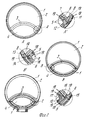
На фиг. 1,А представлен горизонтальный вид в разрезе верхней части известного доменного воздухонагревателя, на фиг. 1,А' деталь А, показанная на фиг. 1А; на фиг. 1,B горизонтальный вид в разрезе нижней части того же доменного воздухонагревателя; на фиг. 1,B' деталь В, представленная на фиг. 1B; на фиг. 1,C и 1,C' аналогичный горизонтальный вид в разрезе и вид в увеличенном масштабе детали воздухонагревателя в нижней части; на фиг. 2,A, 2,A', 2,B, 2,B', 2,C и 2,C' виды в разрезе в увеличенном масштабе, соответствующие видам на фиг. 1,A, 1, A', 1,B, 1,B', 1,C и 1,C' доменного воздухонагревателя в соответствии с изобретением. In FIG. 1A is a horizontal sectional view of the upper part of a known blast furnace; FIG. 1 A ', part A shown in FIG. 1A; in FIG. 1, B is a horizontal sectional view of the lower part of the same blast furnace; in FIG. 1, B ', part B shown in FIG. 1B; in FIG. 1, C and 1, C 'a similar horizontal sectional view and an enlarged view of a part of an air heater in the lower part; in FIG. 2, A, 2, A ′, 2, B, 2, B ′, 2, C and 2, C ′ are sectional views on an enlarged scale corresponding to the views in FIG. 1, A, 1, A ', 1, B, 1, B', 1, C and 1, C 'of a blast furnace in accordance with the invention.
На фиг. 1,A, 1,В и 1,С показана цилиндрическая окружающая стенка 1 доменного воздухонагревателя, внутри которой установлена перегородка 3, отделяющая камеру 2 насадки от камеры 4 горелки. Перегородка 3 соединена на каждом конце окружающей стенки в месте соединения стенок. Известные детали доменного воздухонагревателя, не затронутые настоящим изобретением, не требуют обсуждения здесь. Стенки 1, 3 имеют слои предварительно прессованных и прокаленных кирпичей 5, 6, 7, 8, 9, 10. В нижней части, показанной на фиг. 1С и 1С', камера 4 горелка снабжена дополнительными слоями предварительно спрессованных и спеченных кирпичей 8, 9, 10 для стенок. Может также присутствовать дополнительный промежуточный слой 18. In FIG. 1, A, 1, B and 1, C, the cylindrical surrounding
Фиг. 1,A', 1,B', и 1,C' показывают, что в местах соединения стенок каждый соединительный кирпич, т.е. кирпичи, которые по существу образуют части обеих стенок, имеет свою собственную конкретную форму, определенную его местоположением, таким образом требуется широкое разнообразие соединительных кирпичей. Изобретение можно использовать для таких стенок или слоев стенок, состоящих в основном или по существу из кирпичей. FIG. 1, A ', 1, B', and 1, C 'show that in the joints of the walls each connecting brick, i.e. the bricks, which essentially form part of both walls, have their own specific shape, determined by its location, so a wide variety of connecting bricks is required. The invention can be used for such walls or layers of walls consisting mainly or essentially of bricks.
Соответствующий вид на фиг. 2,A, 2,A', 2,B, 2,B', 2,C и 2,C' доменного воздухонагревателя согласно изобретению показывает, что предварительно спрессованные и прокаленные соединительные кирпичи заменены литыми соединительными элементами 11, 12, 13, 14, 15, 16, 17, отлитые из огнеупорного бетона. Как показано в горизонтальном разрезе, имеется литой соединительный элемент, соответствующий каждой паре соединенных слоев кирпичей. Таким образом на фиг. 2,A' стенки 1, 3 соединены литым соединительным элементом 11, 12 различной формы. На фиг. 2,B' стенки 1, 3 соединены литым соединительным элементом 13, 14. На фиг. 2,С' стенки 1, 3 соединены литыми соединительными элементами 15, 16, 17.2 Высота каждого литого соединительного элемента 11 - 17 может быть такой же, что и высота одного слоя примыкающих кирпичей или двух слоев смежных кирпичей. На практике нашли приемлемыми оба варианта. The corresponding view in FIG. 2, A, 2, A ′, 2, B, 2, B ′, 2, C, and 2, C ′ of the blast furnace according to the invention shows that the pre-pressed and calcined connecting bricks are replaced by
Показанный доменный воздухонагреватель согласно изобретению в остальном в общем такой же, как и на фиг. 1,A, 1,A'. В одном варианте способа изготовления доменного воздухонагревателя согласно изобретению, показанного на фиг. 2,A, 2,A' и т.д. литые соединительные элементы изготовлены с применением отдельных литейных форм в непосредственной близости от места установки. В другом варианте способа согласно изобретению, соединительные элементы отлиты на месте, как описано далее. Выбор способа зависит от размеров воздухонагревателя, местных условий, доступности, характеристик текучести отливаемого материала и т.д. The blast furnace heater according to the invention shown is otherwise generally the same as in FIG. 1, A, 1, A '. In one embodiment of the manufacturing method of a blast furnace according to the invention shown in FIG. 2, A, 2, A ', etc. cast connecting elements are made using separate molds in the immediate vicinity of the installation site. In another embodiment of the method according to the invention, the connecting elements are molded in place, as described below. The choice of method depends on the size of the heater, local conditions, availability, flow characteristics of the cast material, etc.
В способе литья на месте литых соединительных элементов, когда изготавливается один из слоев стенки, материал прокладки, как например, войлок размещают на границах уложенных кирпичей, а часть опалубки размещают границу требуемого соединительного элемента, который не окаймлен выложенными кирпичами, образуя таким образом литейную форму для соединительного элемента. Затем жидкий бетон заливают до требуемого уровня. In the casting method in place of molded connecting elements, when one of the wall layers is made, gasket material, such as felt, is placed at the boundaries of the laid bricks, and part of the formwork is placed at the border of the required connecting element, which is not bordered by the laid bricks, thus forming a mold for connecting element. Then the liquid concrete is poured to the required level.
Соединительный элемент очень сложной формы формируется таким образом на месте. Соединительный элемент может проходить по высоте над одним или более слоями стенок 1 и 3. Войлок образует компенсационное соединение 19 на расширение в конструкции. При использовании конструкции доменного воздухонагревателя в соответствии с изобретением можно сконцентрировать места расширения или расширения перегородки 3 у граничных поверхностей соединительных элементов. Отличие изобретения от известного технического решения состоит в том, что там для соединительных элементов должны применяться кирпичи, которые предварительно формуют, прессуют и подвергают обжигу, чтобы удовлетворять строгим требованиям, а изобретение предлагает новый способ, посредством которого значительно упрощается изготовление и снижается стоимость. A very complex connection element is thus formed in place. The connecting element may extend in height above one or more layers of
Соответствующие литейные материалы для литых соединительных элементов представляют собой литьевые материалы с низким содержанием цемента и высоким содержанием окиси алюминия. Suitable casting materials for cast connecting elements are casting materials with a low cement content and a high alumina content.
Claims (10)
Applications Claiming Priority (2)
| Application Number | Priority Date | Filing Date | Title |
|---|---|---|---|
| NL9200134A NL9200134A (en) | 1992-01-24 | 1992-01-24 | WIND HEATER WITH CAST CONNECTING ELEMENTS AND METHOD FOR BUILDING A WIND HEATER. |
| NL9200134 | 1992-01-24 |
Publications (2)
| Publication Number | Publication Date |
|---|---|
| RU93004438A RU93004438A (en) | 1995-04-20 |
| RU2069700C1 true RU2069700C1 (en) | 1996-11-27 |
Family
ID=19860347
Family Applications (1)
| Application Number | Title | Priority Date | Filing Date |
|---|---|---|---|
| RU9393004438A RU2069700C1 (en) | 1992-01-24 | 1993-01-22 | Blast furnace air heater and method of its production |
Country Status (13)
| Country | Link |
|---|---|
| US (1) | US5375817A (en) |
| EP (1) | EP0552832A1 (en) |
| CN (1) | CN1035392C (en) |
| AU (1) | AU653881B2 (en) |
| CA (1) | CA2087465C (en) |
| CZ (1) | CZ7093A3 (en) |
| FI (1) | FI101084B (en) |
| MX (1) | MX9300315A (en) |
| NL (1) | NL9200134A (en) |
| PL (1) | PL170673B1 (en) |
| RU (1) | RU2069700C1 (en) |
| SK (1) | SK2493A3 (en) |
| ZA (1) | ZA93437B (en) |
Cited By (1)
| Publication number | Priority date | Publication date | Assignee | Title |
|---|---|---|---|---|
| RU2615383C1 (en) * | 2013-08-06 | 2017-04-04 | Ниппон Стил Энд Сумикин Инджиниринг Ко., Лтд. | Method of manufacturing hot blow air heater |
Families Citing this family (9)
| Publication number | Priority date | Publication date | Assignee | Title |
|---|---|---|---|---|
| NL9201838A (en) * | 1992-10-23 | 1994-05-16 | Hoogovens Groep Bv | Hot wind pipe. |
| SE529586C2 (en) * | 2004-09-14 | 2007-09-25 | North Cape Minerals As | Ways of making abrasive liners in casters and casters |
| ZA200706342B (en) * | 2005-02-01 | 2008-11-26 | Danieli Corus Bv | Support assembly for supporting heat regeneration checker work in a hot blast stove, hot blast stove provided with said support assembly, method of producing hot air using said hot blast stove |
| ES2582863T3 (en) * | 2010-02-12 | 2016-09-15 | Allied Mineral Products, Inc. | Cowper stove and cowper stove dome |
| CN102747177B (en) * | 2012-07-30 | 2013-08-21 | 王继平 | Blast furnace hot blast stove and construction method thereof |
| CN103278015A (en) * | 2013-01-11 | 2013-09-04 | 成都蜀冶新材料有限责任公司 | Integral casting method for stove top refractory lining of hot blast stove |
| CN103629935B (en) * | 2013-02-05 | 2016-08-24 | 绵竹市剑桥节能材料有限公司 | Brick field tunnel cave, rotary kiln hydrophobic type insulation ceiling board |
| CN103484589B (en) * | 2013-09-13 | 2015-01-07 | 中国十九冶集团有限公司 | Low-temperature hot blast heater construction method |
| CN105441618B (en) * | 2015-12-07 | 2017-08-29 | 北京首钢股份有限公司 | A kind of blast funnace hot blast stove vault local route repair method |
Family Cites Families (9)
| Publication number | Priority date | Publication date | Assignee | Title |
|---|---|---|---|---|
| US2035309A (en) * | 1933-06-12 | 1936-03-24 | William H Fitch | Recuperator wall |
| US2903778A (en) * | 1955-11-28 | 1959-09-15 | Southern Lightweight Aggregate | Lightweight aggregate furnace patch lining and process of applying |
| US3048481A (en) * | 1958-06-18 | 1962-08-07 | Texaco Inc | Method of forming gas tight seal between vessel wall and refractory lining of a synthesis gas generator |
| DE2426093B2 (en) * | 1974-05-30 | 1978-08-10 | Brohltal-Deumag Ag Fuer Feuerfeste Erzeugnisse, 5401 Urmitz | Wind heater with internal combustion shaft |
| US4221537A (en) * | 1978-08-21 | 1980-09-09 | Andco Incorporated | Hot blast stove erection process |
| FR2439374A1 (en) * | 1978-10-19 | 1980-05-16 | Usinor | METHOD FOR COATING THE INTERNAL WALL OF AN OVEN OR THE LIKE |
| DE2929718B1 (en) * | 1979-07-21 | 1980-12-04 | Didier Werke Ag | Hot water heater with internal burner shaft |
| DE3218126C1 (en) * | 1982-05-14 | 1983-09-29 | Aktiengesellschaft der Dillinger Hüttenwerke, 6638 Dillingen | Blast heater for blast furnaces |
| GB2172982B (en) * | 1985-03-25 | 1988-05-18 | Davy Mckee | Hot blast stoves |
-
1992
- 1992-01-24 NL NL9200134A patent/NL9200134A/en not_active Application Discontinuation
-
1993
- 1993-01-15 EP EP93200089A patent/EP0552832A1/en not_active Withdrawn
- 1993-01-18 CA CA002087465A patent/CA2087465C/en not_active Expired - Fee Related
- 1993-01-21 AU AU31928/93A patent/AU653881B2/en not_active Ceased
- 1993-01-21 ZA ZA93437A patent/ZA93437B/en unknown
- 1993-01-22 RU RU9393004438A patent/RU2069700C1/en active
- 1993-01-22 SK SK2493A patent/SK2493A3/en unknown
- 1993-01-22 MX MX9300315A patent/MX9300315A/en not_active IP Right Cessation
- 1993-01-22 FI FI930275A patent/FI101084B/en active IP Right Grant
- 1993-01-22 PL PL93297513A patent/PL170673B1/en unknown
- 1993-01-22 CZ CZ9370A patent/CZ7093A3/en unknown
- 1993-01-24 CN CN93102074A patent/CN1035392C/en not_active Expired - Fee Related
-
1994
- 1994-01-14 US US08/181,452 patent/US5375817A/en not_active Expired - Fee Related
Non-Patent Citations (1)
| Title |
|---|
| Патент США N 4369954, кл. C 21 B 9/02, 1983. * |
Cited By (1)
| Publication number | Priority date | Publication date | Assignee | Title |
|---|---|---|---|---|
| RU2615383C1 (en) * | 2013-08-06 | 2017-04-04 | Ниппон Стил Энд Сумикин Инджиниринг Ко., Лтд. | Method of manufacturing hot blow air heater |
Also Published As
| Publication number | Publication date |
|---|---|
| SK2493A3 (en) | 1993-09-09 |
| PL297513A1 (en) | 1993-09-20 |
| CA2087465A1 (en) | 1993-07-25 |
| MX9300315A (en) | 1993-07-01 |
| CZ7093A3 (en) | 1993-08-11 |
| AU3192893A (en) | 1993-07-29 |
| FI930275A0 (en) | 1993-01-22 |
| FI101084B (en) | 1998-04-15 |
| AU653881B2 (en) | 1994-10-13 |
| CA2087465C (en) | 1999-09-21 |
| EP0552832A1 (en) | 1993-07-28 |
| US5375817A (en) | 1994-12-27 |
| FI930275A (en) | 1993-07-25 |
| ZA93437B (en) | 1993-08-25 |
| NL9200134A (en) | 1993-08-16 |
| CN1076218A (en) | 1993-09-15 |
| CN1035392C (en) | 1997-07-09 |
| PL170673B1 (en) | 1997-01-31 |
Similar Documents
| Publication | Publication Date | Title |
|---|---|---|
| US2201110A (en) | Brick or block | |
| RU2069700C1 (en) | Blast furnace air heater and method of its production | |
| US4770828A (en) | Heat exchangers molded from refractory material | |
| US8641940B2 (en) | Method for constructing a monolithic refractory concrete furnace for the manufacture of glass | |
| IT1136411B (en) | COMPLEX OF SPACER ELEMENTS AND ALIGNERS FOR BLOCKS PARTICULARLY SUITABLE FOR WALLS OR CONCRETE GLASS PANELS | |
| AU2008248631B2 (en) | Method for constructing a support ring in a curved wall | |
| JP3769256B2 (en) | RH degassing tank bottom, RH degassing tank, and refractory block manufacturing method | |
| CN101498552B (en) | Molten pool working layer of aluminum melting furnace built by flame-proof precast blocks | |
| US1041389A (en) | Concrete wall construction. | |
| US5423519A (en) | Regenerative chamber lining and method of installation | |
| CN212248330U (en) | Coke oven bottom large-volume high-strength castable layered block construction structure and mold | |
| RU1819313C (en) | Building block | |
| WO2020203426A1 (en) | Crown structure and production method therefor | |
| US8016259B2 (en) | Refractory furnace covers and methods of constructing same | |
| SU696126A1 (en) | Constraction wall block | |
| JPH11277191A (en) | Method for working tundish refractory and structure thereof | |
| SU787586A1 (en) | Three-dimensional block | |
| CA2050722A1 (en) | Monolithic refractory lining | |
| JPH0633532A (en) | Precast concrete slab and manufacture thereof | |
| JPH0724812A (en) | Production of ceramic cap | |
| GB191327574A (en) | Improved Means for Constructing Walls and Blocks therefor. | |
| JPH04124053A (en) | Heat-resistant block | |
| ITRM940793A1 (en) | SELF-ASSEMBLING PRINTED BRICK BUILDING SYSTEM |