RU2060164C1 - Multilayer material and culinary vessel made of this material - Google Patents
Multilayer material and culinary vessel made of this material Download PDFInfo
- Publication number
- RU2060164C1 RU2060164C1 SU925011219A SU5011219A RU2060164C1 RU 2060164 C1 RU2060164 C1 RU 2060164C1 SU 925011219 A SU925011219 A SU 925011219A SU 5011219 A SU5011219 A SU 5011219A RU 2060164 C1 RU2060164 C1 RU 2060164C1
- Authority
- RU
- Russia
- Prior art keywords
- metal
- relatively soft
- aluminum
- lattice
- layer
- Prior art date
Links
Images


Classifications
-
- B—PERFORMING OPERATIONS; TRANSPORTING
- B23—MACHINE TOOLS; METAL-WORKING NOT OTHERWISE PROVIDED FOR
- B23P—METAL-WORKING NOT OTHERWISE PROVIDED FOR; COMBINED OPERATIONS; UNIVERSAL MACHINE TOOLS
- B23P11/00—Connecting or disconnecting metal parts or objects by metal-working techniques not otherwise provided for
-
- A—HUMAN NECESSITIES
- A47—FURNITURE; DOMESTIC ARTICLES OR APPLIANCES; COFFEE MILLS; SPICE MILLS; SUCTION CLEANERS IN GENERAL
- A47J—KITCHEN EQUIPMENT; COFFEE MILLS; SPICE MILLS; APPARATUS FOR MAKING BEVERAGES
- A47J36/00—Parts, details or accessories of cooking-vessels
-
- A—HUMAN NECESSITIES
- A47—FURNITURE; DOMESTIC ARTICLES OR APPLIANCES; COFFEE MILLS; SPICE MILLS; SUCTION CLEANERS IN GENERAL
- A47J—KITCHEN EQUIPMENT; COFFEE MILLS; SPICE MILLS; APPARATUS FOR MAKING BEVERAGES
- A47J27/00—Cooking-vessels
- A47J27/002—Construction of cooking-vessels; Methods or processes of manufacturing specially adapted for cooking-vessels
-
- A—HUMAN NECESSITIES
- A47—FURNITURE; DOMESTIC ARTICLES OR APPLIANCES; COFFEE MILLS; SPICE MILLS; SUCTION CLEANERS IN GENERAL
- A47J—KITCHEN EQUIPMENT; COFFEE MILLS; SPICE MILLS; APPARATUS FOR MAKING BEVERAGES
- A47J36/00—Parts, details or accessories of cooking-vessels
- A47J36/02—Selection of specific materials, e.g. heavy bottoms with copper inlay or with insulating inlay
-
- B—PERFORMING OPERATIONS; TRANSPORTING
- B21—MECHANICAL METAL-WORKING WITHOUT ESSENTIALLY REMOVING MATERIAL; PUNCHING METAL
- B21K—MAKING FORGED OR PRESSED METAL PRODUCTS, e.g. HORSE-SHOES, RIVETS, BOLTS OR WHEELS
- B21K25/00—Uniting components to form integral members, e.g. turbine wheels and shafts, caulks with inserts, with or without shaping of the components
-
- B—PERFORMING OPERATIONS; TRANSPORTING
- B23—MACHINE TOOLS; METAL-WORKING NOT OTHERWISE PROVIDED FOR
- B23K—SOLDERING OR UNSOLDERING; WELDING; CLADDING OR PLATING BY SOLDERING OR WELDING; CUTTING BY APPLYING HEAT LOCALLY, e.g. FLAME CUTTING; WORKING BY LASER BEAM
- B23K20/00—Non-electric welding by applying impact or other pressure, with or without the application of heat, e.g. cladding or plating
- B23K20/002—Non-electric welding by applying impact or other pressure, with or without the application of heat, e.g. cladding or plating specially adapted for particular articles or work
-
- B—PERFORMING OPERATIONS; TRANSPORTING
- B23—MACHINE TOOLS; METAL-WORKING NOT OTHERWISE PROVIDED FOR
- B23P—METAL-WORKING NOT OTHERWISE PROVIDED FOR; COMBINED OPERATIONS; UNIVERSAL MACHINE TOOLS
- B23P2700/00—Indexing scheme relating to the articles being treated, e.g. manufactured, repaired, assembled, connected or other operations covered in the subgroups
- B23P2700/05—Cooking vessels
-
- Y—GENERAL TAGGING OF NEW TECHNOLOGICAL DEVELOPMENTS; GENERAL TAGGING OF CROSS-SECTIONAL TECHNOLOGIES SPANNING OVER SEVERAL SECTIONS OF THE IPC; TECHNICAL SUBJECTS COVERED BY FORMER USPC CROSS-REFERENCE ART COLLECTIONS [XRACs] AND DIGESTS
- Y10—TECHNICAL SUBJECTS COVERED BY FORMER USPC
- Y10S—TECHNICAL SUBJECTS COVERED BY FORMER USPC CROSS-REFERENCE ART COLLECTIONS [XRACs] AND DIGESTS
- Y10S220/00—Receptacles
- Y10S220/912—Cookware, i.e. pots and pans
-
- Y—GENERAL TAGGING OF NEW TECHNOLOGICAL DEVELOPMENTS; GENERAL TAGGING OF CROSS-SECTIONAL TECHNOLOGIES SPANNING OVER SEVERAL SECTIONS OF THE IPC; TECHNICAL SUBJECTS COVERED BY FORMER USPC CROSS-REFERENCE ART COLLECTIONS [XRACs] AND DIGESTS
- Y10—TECHNICAL SUBJECTS COVERED BY FORMER USPC
- Y10T—TECHNICAL SUBJECTS COVERED BY FORMER US CLASSIFICATION
- Y10T29/00—Metal working
- Y10T29/49—Method of mechanical manufacture
- Y10T29/49826—Assembling or joining
- Y10T29/49888—Subsequently coating
-
- Y—GENERAL TAGGING OF NEW TECHNOLOGICAL DEVELOPMENTS; GENERAL TAGGING OF CROSS-SECTIONAL TECHNOLOGIES SPANNING OVER SEVERAL SECTIONS OF THE IPC; TECHNICAL SUBJECTS COVERED BY FORMER USPC CROSS-REFERENCE ART COLLECTIONS [XRACs] AND DIGESTS
- Y10—TECHNICAL SUBJECTS COVERED BY FORMER USPC
- Y10T—TECHNICAL SUBJECTS COVERED BY FORMER US CLASSIFICATION
- Y10T29/00—Metal working
- Y10T29/49—Method of mechanical manufacture
- Y10T29/49826—Assembling or joining
- Y10T29/49908—Joining by deforming
-
- Y—GENERAL TAGGING OF NEW TECHNOLOGICAL DEVELOPMENTS; GENERAL TAGGING OF CROSS-SECTIONAL TECHNOLOGIES SPANNING OVER SEVERAL SECTIONS OF THE IPC; TECHNICAL SUBJECTS COVERED BY FORMER USPC CROSS-REFERENCE ART COLLECTIONS [XRACs] AND DIGESTS
- Y10—TECHNICAL SUBJECTS COVERED BY FORMER USPC
- Y10T—TECHNICAL SUBJECTS COVERED BY FORMER US CLASSIFICATION
- Y10T29/00—Metal working
- Y10T29/49—Method of mechanical manufacture
- Y10T29/4998—Combined manufacture including applying or shaping of fluent material
- Y10T29/49982—Coating
- Y10T29/49986—Subsequent to metal working
-
- Y—GENERAL TAGGING OF NEW TECHNOLOGICAL DEVELOPMENTS; GENERAL TAGGING OF CROSS-SECTIONAL TECHNOLOGIES SPANNING OVER SEVERAL SECTIONS OF THE IPC; TECHNICAL SUBJECTS COVERED BY FORMER USPC CROSS-REFERENCE ART COLLECTIONS [XRACs] AND DIGESTS
- Y10—TECHNICAL SUBJECTS COVERED BY FORMER USPC
- Y10T—TECHNICAL SUBJECTS COVERED BY FORMER US CLASSIFICATION
- Y10T428/00—Stock material or miscellaneous articles
- Y10T428/12—All metal or with adjacent metals
- Y10T428/12486—Laterally noncoextensive components [e.g., embedded, etc.]
-
- Y—GENERAL TAGGING OF NEW TECHNOLOGICAL DEVELOPMENTS; GENERAL TAGGING OF CROSS-SECTIONAL TECHNOLOGIES SPANNING OVER SEVERAL SECTIONS OF THE IPC; TECHNICAL SUBJECTS COVERED BY FORMER USPC CROSS-REFERENCE ART COLLECTIONS [XRACs] AND DIGESTS
- Y10—TECHNICAL SUBJECTS COVERED BY FORMER USPC
- Y10T—TECHNICAL SUBJECTS COVERED BY FORMER US CLASSIFICATION
- Y10T428/00—Stock material or miscellaneous articles
- Y10T428/12—All metal or with adjacent metals
- Y10T428/12493—Composite; i.e., plural, adjacent, spatially distinct metal components [e.g., layers, joint, etc.]
- Y10T428/12535—Composite; i.e., plural, adjacent, spatially distinct metal components [e.g., layers, joint, etc.] with additional, spatially distinct nonmetal component
- Y10T428/12556—Organic component
- Y10T428/12569—Synthetic resin
-
- Y—GENERAL TAGGING OF NEW TECHNOLOGICAL DEVELOPMENTS; GENERAL TAGGING OF CROSS-SECTIONAL TECHNOLOGIES SPANNING OVER SEVERAL SECTIONS OF THE IPC; TECHNICAL SUBJECTS COVERED BY FORMER USPC CROSS-REFERENCE ART COLLECTIONS [XRACs] AND DIGESTS
- Y10—TECHNICAL SUBJECTS COVERED BY FORMER USPC
- Y10T—TECHNICAL SUBJECTS COVERED BY FORMER US CLASSIFICATION
- Y10T428/00—Stock material or miscellaneous articles
- Y10T428/12—All metal or with adjacent metals
- Y10T428/12493—Composite; i.e., plural, adjacent, spatially distinct metal components [e.g., layers, joint, etc.]
- Y10T428/12736—Al-base component
- Y10T428/1275—Next to Group VIII or IB metal-base component
- Y10T428/12757—Fe
Landscapes
- Engineering & Computer Science (AREA)
- Mechanical Engineering (AREA)
- Food Science & Technology (AREA)
- Manufacturing & Machinery (AREA)
- Cookers (AREA)
- Table Devices Or Equipment (AREA)
- Forging (AREA)
- Frying-Pans Or Fryers (AREA)
- Baking, Grill, Roasting (AREA)
Abstract
Description
Предлагаемое изобретение касается многослойного материала, выполненного на основе относительно мягкого металла, например алюминия. The present invention relates to a multilayer material made on the basis of a relatively soft metal, for example aluminum.
Данное изобретение имеет своей целью также хозяйственные сосуды кулинарного назначения, представляющие собой изделия, выполненные из заявленного материала. This invention also aims at culinary household vessels, which are products made from the claimed material.
Металлом, о котором идет речь в предлагаемом изобретении, может быть, в частности, алюминий. Алюминий является металлом, который обладает многочисленными благоприятными свойствами, обеспечивающими ему преимущество перед многими другими металлами. Он относительно легок, хорошо поддается штамповке и вытяжке, обладает достаточно высокой теплопроводностью. Кроме того, алюминий относительно дешев и экономичен в обработке. Вследствие этих и других своих качеств алюминий получил весьма широкое распространение и практически универсально используется в промышленности. В частности, алюминий и его сплавы широко используются для изготовления кухонной посуды или кулинарных сосудов. The metal in question in the present invention may be, in particular, aluminum. Aluminum is a metal that has numerous favorable properties that provide it with an advantage over many other metals. It is relatively light, lends itself well to stamping and drawing, has a sufficiently high thermal conductivity. In addition, aluminum is relatively cheap and economical to process. Due to these and other qualities, aluminum has become very widespread and is almost universally used in industry. In particular, aluminum and its alloys are widely used for the manufacture of cookware or cooking vessels.
Алюминий, однако, обладает и целым рядом недостатков. Прежде всего, этот металл относительно мягок, в результате чего поверхность изделия из алюминия в процессе эксплуатации легко покрывается царапинами. При изготовлении изделий хозяйственного назначения алюминий часто покрывают слоем антиадгезионного материала, например слоем политетрафторэтилена или слоем эмали. Однако срок службы подобных покрытий ограничен вследствие того, что алюминий представляет собой слишком мягкую основу. Aluminum, however, has a number of disadvantages. First of all, this metal is relatively soft, as a result of which the surface of an aluminum product is easily scratched during operation. In the manufacture of household products, aluminum is often coated with a layer of release material, such as a layer of polytetrafluoroethylene or a layer of enamel. However, the service life of such coatings is limited due to the fact that aluminum is too soft a base.
Кроме того, различные изделия из алюминия и в особенности кулинарные сосуды, предназначенные для приготовления пищи, имеют тенденцию сравнительно легко деформироваться под действием потока тепловой энергии, исходящего, например, от нагревательного элемента электрической кухонной плиты или от газовой горелки плиты, работающей на газе. In addition, various aluminum products and in particular cooking vessels intended for cooking tend to be relatively easily deformed by the flow of thermal energy emanating, for example, from a heating element of an electric stove or gas burner of a gas stove.
Для устранения этого недостатка можно либо увеличивать толщину металла, из которого изготовлено то или иное изделие, либо накладывать на соответствующую поверхность изделия из алюминия лист нержавеющей стали. Это можно сделать, например, методом горячей штамповки. Однако в этом случае существенно возрастает стоимость производства такого изделия и снижается теплопроводность соответствующих поверхностей кулинарных сосудов, что приводит к увеличению времени приготовления блюд. To eliminate this drawback, you can either increase the thickness of the metal from which this or that product is made, or apply a stainless steel sheet to the corresponding surface of the aluminum product. This can be done, for example, by hot stamping. However, in this case, the cost of production of such a product substantially increases and the thermal conductivity of the corresponding surfaces of the culinary vessels decreases, which leads to an increase in the cooking time.
Кроме того, кухонная посуда из алюминия не может быть подвергнута индукционному нагреву, поскольку этот способ нагрева требует использования посуды, изготовленной из металла, обладающего магнитными свойствами, например из специальной магнитной нержавеющей стали пищевого качества. In addition, aluminum cookware cannot be subjected to induction heating, since this heating method requires the use of cookware made of metal having magnetic properties, for example, of special food-grade magnetic stainless steel.
Цель предлагаемого изобретения состоит в том, чтобы достаточно экономичным образом модифицировать характеристики поверхности металла с тем, чтобы в необходимом направлении усовершенствовать его свойства или сделать этот метал пригодным для использования в некоторых специфических условиях. The purpose of the invention is to modify the surface characteristics of a metal in an economical way in order to improve its properties in the necessary direction or make this metal suitable for use in certain specific conditions.
Материал в соответствии с предлагаемым изобретением, созданный из относительно мягкого металла, используемого, например, в виде пластины, отличается тем, что эта пластина на одной из своих сторон снабжена дополнительным металлическим элементом в виде перфорированного листа или решетки, изготовленных из другого металла или сплава, более твердого, чем металла, из которого изготовлена упомянутая выше пластина, причем упомянутый выше металлический элемент закрепляется на упомянутой выше пластине при помощи холодной штамповки или удара с целью по меньшей мере частичного вдавливания этого элемента в металла пластины. The material in accordance with the invention, created from a relatively soft metal, used, for example, in the form of a plate, characterized in that this plate on one of its sides is provided with an additional metal element in the form of a perforated sheet or lattice made of another metal or alloy, harder than the metal of which the aforementioned plate is made, the aforementioned metal element being fixed to the aforementioned plate by cold stamping or impact with Spruce at least partial indentation of this element in the metal plate.
Под штамповкой в данном случае понимается технологическая операция, которая состоит в ударе, например, с помощью падающего молота или в сильном надавливании, например, посредством плоской поверхности или валка на упомянутую выше решетку для ее вдавливания, по меньшей мере частичного, в поверхность металла пластины для закрепления на этой поверхности. In this case, stamping is understood as a technological operation, which consists in impact, for example, with the help of a falling hammer or in strong pressure, for example, by means of a flat surface or a roll on the above-mentioned grating for pressing it, at least partially, into the surface of the metal of the plate for fixing on this surface.
Под решеткой в данном случае следует понимать не только металлический элемент в виде системы взаимно перекрещивающихся проволок, но также и перфорированный металлический лист с отверстиями круглой, квадратной или любой другой формы. In this case, a grid should be understood not only as a metal element in the form of a system of mutually crossed wires, but also as a perforated metal sheet with holes of a round, square, or any other shape.
Описанным выше способом получают композитную или составную поверхность, обладающую специфическими свойствами, результирующими свойства двух составляющих ее металлов, т.е. основного металла, из которого изготовлена пластина-матрица, и металла, из которого изготовлена решетка. Другими словами, свойства основного металла модифицируются наличием решетки, которая плотно соединена с этим основным металлом. By the method described above, a composite or composite surface is obtained having specific properties resulting in the properties of the two metals constituting it, i.e. the base metal of which the matrix plate is made, and the metal of which the lattice is made. In other words, the properties of the base metal are modified by the presence of a lattice that is tightly connected to this base metal.
Например, в том случае, когда упомянутая выше решетка изготовлена из металла, более твердого, чем основной металл, наличие этой решетки будет иметь следствием придание большей твердости поверхности основного металла. For example, in the case when the above-mentioned lattice is made of a metal harder than the base metal, the presence of this lattice will result in imparting a greater hardness to the surface of the base metal.
В то же время, использованием решетки из более твердого металла в соединении с относительно мягким основным металлом достаточно хорошо адаптировано к практической реализации изделий в соответствии с предлагаемым изобретением, поскольку в процессе холодной штамповки или удара твердая металлическая решетка, имеющая малую площадь поверхности соприкосновения с пластиной основного металла, глубоко проникает в толщу этого относительно мягкого металла, что обеспечивает превосходное соединение этой решетки с основным металлом пластины. At the same time, using a harder made of harder metal in combination with a relatively soft base metal, it is quite well adapted to the practical implementation of the products in accordance with the invention, since in the process of cold stamping or impact a solid metal lattice having a small contact area with the base plate metal, penetrates deep into the thickness of this relatively soft metal, which provides an excellent connection of this lattice with the base metal of the plate.
С другой стороны, в том случае, если основной металл подвержен существенной деформации под действием потока тепловой энергии, наличие упомянутой выше решетки (в том числе, если эта решетка изготовлена из металла с меньшим тепловым коэффициентом расширения по сравнению с коэффициентом теплового расширения основного металла) приведет к тому, что основной металл станет существенно менее деформируемым в зависимости от температуры. On the other hand, if the base metal is subject to significant deformation under the influence of the flow of thermal energy, the presence of the above-mentioned lattice (including if this lattice is made of metal with a lower thermal expansion coefficient compared to the thermal expansion coefficient of the base metal) to the fact that the base metal will become significantly less deformable depending on temperature.
В одном из возможных вариантов практического применения предлагаемого изобретения в тех случаях, когда основной металл не обладает магнитными свойствами (такими свойствами не обладает, например, алюминий наиболее предпочтительный материал для использования его в качестве основного металла), в соответствии с предлагаемым изобретением наличие упомянутой выше решетки, изготовленной из металла, обладающего определенными магнитными свойствами и плотно соединенной с поверхностью основного металла, переводит изделие, созданное в соответствии с предлагаемым изобретением, в разряд пригодных для индукционного нагрева. In one of the possible practical applications of the present invention in cases where the base metal does not possess magnetic properties (for example, aluminum does not have such properties as the most preferred material for use as the base metal), in accordance with the invention, the presence of the above-mentioned lattice made of a metal having certain magnetic properties and tightly connected to the surface of the base metal translates the product created in accordance with Twi with the invention, in a category suitable for induction heating.
Во всех этих и подобных им случаях внесение другого металла в форме плотно присоединенной решетки в массу используемого в данном применении основного металла не увеличивает слишком сильно стоимость конечного изделия и позволяет сохранить в неприкосновенности основные положительные свойства основного металла. In all these and similar cases, the introduction of another metal in the form of a tightly attached lattice into the mass of the base metal used in this application does not increase too much the cost of the final product and allows you to maintain the basic positive properties of the base metal intact.
В соответствии с другими вариантами практической реализации предлагаемого изобретения заявленный материал обладает на каждой из двух своих сторон металлическими решетчатым элементом, отвечающим данному выше определению. In accordance with other variants of the practical implementation of the invention, the claimed material has a metal lattice element on each of its two sides that meets the above definition.
Возможен также такой вариант практической реализации предлагаемого изобретения, при котором поверхность присоединенного металлического элемента или элементов, противоположная пластине из основного металла, имеет покрытие из металла, идентичного основному металлу пластины. It is also possible such a variant of the practical implementation of the present invention, in which the surface of the attached metal element or elements, opposite the plate of the base metal, has a coating of metal identical to the base metal of the plate.
В соответствии с еще одним вариантом практической реализации предлагаемого изобретения каждая поверхность пластины из основного металла, на которой закреплен упомянутый выше дополнительный решетчатый металлический элемент, покрыта сплошным слоем эмали или фтороуглеродной смолы. In accordance with yet another embodiment of the present invention, each surface of a base metal plate on which the aforementioned additional lattice metal element is fixed is coated with a continuous layer of enamel or fluorocarbon resin.
Еще один возможный вариант практической реализации предлагаемого изобретения состоит в том, что соответствующее конечное изделие включает по меньшей мере две металлические пластины, скрепленные между собой и содержащие в плоскости соединения вставной металлической решетчатый элемент, который частично вдавлен в металл как одной, так и другой пластины. Another possible variant of the practical implementation of the invention is that the corresponding final product includes at least two metal plates fastened together and containing in the plane of the connection an insertable metal lattice element that is partially pressed into the metal of one or the other plate.
Таким образом, предлагаемое изобретение позволяет усилить изготовленные из алюминия донные части кулинарных сосудов. Оно также дает возможность увеличить срок службы антиадгезионных покрытий этих сосудов и сделать эти сосуды восприимчивыми к индукционному нагреву в том случае, когда встроенная металлическая решетка изготовлена из металла, обладающего магнитными свойствами, например из специальной магнитной нержавеющей стали. Thus, the present invention allows to strengthen made from aluminum bottom parts of the culinary vessels. It also makes it possible to increase the service life of the release coatings of these vessels and make these vessels susceptible to induction heating when the built-in metal grating is made of metal having magnetic properties, for example, special magnetic stainless steel.
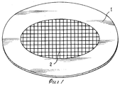
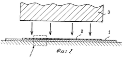
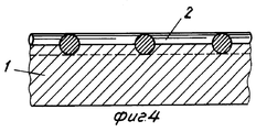
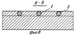
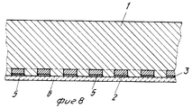
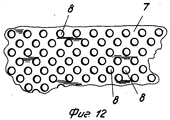
На фиг.1 изображен общий вид заявленного материала, выполненного в виде металлического диска, на который в соответствии с предлагаемым изобретением наложена и закреплена решетка из металла, отличного от того металла, из которого сам диск; на фиг.2 вид в разрезе, схематически показывающий способ штамповочного закрепления металлической решетки на пластине из основного металла; на фиг.3 в увеличенном масштабе показан узел I на фиг.2; на фиг.4 изображение, аналогичное показанному на фиг.3 и демонстрирующее металлическую решетку, вдавленную в металл диска после штамповки; на фиг.5 увеличенный вид в плане на металлическую решетку, закрепленную на поверхности пластины основного металла; на фиг.6 разрез Б-Б на фиг.5; на фиг.7 вид в разрезе пластины основного металла, содержащий на двух своих сторонах перфорированный металлический лист, закрепленный вдавливанием в толщу металла упомянутой выше пластины; на фиг.8 разрез заявленного материала, на котором поверхность упомянутого выше перфорированного листа или решетки, противоположная пластине основного металла, имеет покрытие из металла, идентичного упомянутому выше основному металлу; на фиг.9 вид, подобный изображенному на фиг. 8, и представляющий собой вариант практической реализации предлагаемого изображения; на фиг.10 вид в разрезе, показывающий две пластины из основного металла и три перфорированных листа из вспомогательного металла перед их соединением в единый агрегат методом штамповки; на фиг.11 вид в разрезе полученной упомянутым выше образом композитной или составной пластины после выполнения операции штамповки; на фиг.12 вид в плане на перфорированный металлический лист; на фиг.13 частичный вид в разрезе на пластину из основного металла, несущую на себе перфорированный металлический лист из другого металла, частично вдавленный в эту пластину; на фиг.14 схематичный вид в разрезе на композитную пластину из основного металла, заключающуюся в себе два перфорированный листа из другого металла; на фиг.15 частичный вид в плане металлического элемента в форме растянутого листа; на фиг.16 вид в разрезе на кулинарный сосуд, несущий решетку из другого металла на наружной стороне своей донной части; на фиг.17 в увеличенном масштабе узел II на фиг.16; на фиг.18 вид в разрезе кулинарного сосуда из некоторого металла, несущего решетку из другого металла на внутренней стороне своей донной части; на фиг.19 в увеличенном масштабе узел III на фиг.18. Figure 1 shows a General view of the claimed material, made in the form of a metal disk, on which in accordance with the invention is superimposed and fixed a lattice of metal other than the metal of which the disk itself; FIG. 2 is a sectional view schematically showing a stamping method of fixing a metal grate to a base metal plate; figure 3 on an enlarged scale shows the node I in figure 2; in Fig.4 an image similar to that shown in Fig.3 and showing a metal grill pressed into the metal of the disk after stamping; figure 5 is an enlarged plan view of a metal grid mounted on the surface of the base metal plate; Fig.6 section BB in Fig.5; Fig. 7 is a sectional view of a base metal plate containing on its two sides a perforated metal sheet fixed by pressing in the thickness of the metal of the aforementioned plate; on Fig section of the claimed material, on which the surface of the aforementioned perforated sheet or lattice, opposite the plate of the base metal, has a coating of a metal identical to the aforementioned base metal; FIG. 9 is a view similar to that shown in FIG. 8, and representing an embodiment of the practical implementation of the proposed image; figure 10 is a sectional view showing two plates of a base metal and three perforated sheets of auxiliary metal before joining them into a single unit by stamping; 11 is a sectional view of the composite or composite plate obtained in the above manner after the stamping operation is performed; 12 is a plan view of a perforated metal sheet; 13 is a partial sectional view of a base metal plate bearing a perforated metal sheet of another metal partially pressed into the plate; on Fig schematic view in section on a composite plate of a base metal, consisting of two perforated sheets of another metal; on Fig a partial view in plan of a metal element in the form of a stretched sheet; Fig. 16 is a sectional view of a culinary vessel carrying a grate of another metal on the outside of its bottom; in Fig.17 on an enlarged scale node II in Fig.16; Fig. 18 is a cross-sectional view of a culinary vessel of some metal carrying a grate of another metal on the inside of its bottom; on Fig in an enlarged scale node III in Fig. 18.
Материал, выполненный в соответствии с предлагаемым изобретением на основе пластины, изготовленной из некоторого относительно мягкого металла, отличается тем, что на поверхность 1 упомянутого выше металла (фиг.1 и 2), образующего пластину в форме диска, накладывают решетку 2, изготовленную из некоторого другого металла, и фиксируют эту решетку 2 на упомянутой выше поверхности 1 холодной штамповкой с целью по меньшей мере частично вдавить ее в эту поверхность. A material made in accordance with the invention on the basis of a plate made of some relatively soft metal is characterized in that a
Решетка 2 изготавливается из металла более твердого, чем основной металл поверхности 1 пластины в форме диска. На фиг.3 показана начальная фаза наложения металлической решетки 2 на поверхность диска 1. The
Под действием вертикального усилия, развиваемого падающим молотом 3 (фиг.2) и приложенного к решетке 2, эта решетка погружается или вдавливается в толщу металла диска 1, как показано на фиг.4. (частичное вдавливание). Глубина погружения решетки в основной металл пластины зависит от величины усилия, приложенного к решетке 2 и прижимающего ее к поверхности диска 1, а также от относительной твердости металлов, из которых изготовлены решетки 2 и диск 1, и диаметра проволоки, из которой была изготовлена решетка 2. Under the action of the vertical force developed by the falling hammer 3 (Fig. 2) and applied to the
В случае, схематично показанном на фиг.4, металлическая решетка 2 погружена в металл диска 1 на глубину, соответствующую примерно половине диаметра проволоки, которая была использована для изготовления решетки 2. In the case schematically shown in FIG. 4, the
Прикладывая большее по величине штамповочное усилие, можно вдавливать металлическую решетку 2 в металл диска 1 полностью, на всю ее толщину, как это показано на фиг.6. Applying a larger stamping force, it is possible to press the
Предпочтительным во многих отношениях и относительно мягким металлом для изготовления диска 1 в соответствии с предлагаемым изобретением является алюминий. В то же время, этим относительно мягким металлом могут быть также медь, олово, свинец или сплавы одного или нескольких из этих металлов, а также любые другие подходящие для данного практического применения металлы и сплавы. Preferred in many respects and relatively soft metal for the manufacture of the
Решетка 2 может быть изготовлена из железистой стали, обладающей магнитными свойствами, или из какого-либо другого металла, подходящего для данного случая практического применения предлагаемого изобретения. The
В случае использования решетки 2, изготовленной из металла, обладающего магнитными свойствами, эта решетка, жестко закрепленная на поверхности диска 1, не только усиливает и делает более жестким этот диск, но и придает этому диску способность к индукционному нагреву. In the case of using a
Решетка 2 в соответствии с предлагаемым изобретением может, таким образом, с успехом быть изготовлена из нержавеющей стали, обладающей магнитными свойствами и более твердой, чем алюминий. The
В том случае, когда диск 1 изготавливается из алюминия, а решетка 2 делается из нержавеющей стали и состоит из проволоки диаметром от одного до нескольких десятков миллиметров, используемое усилие при штамповке должно составлять не менее 10 тонн на квадратный сантиметр поверхности. In the case when the
Металлическая решетка 2 в соответствии с предлагаемым изобретением может иметь ячейки любой другой формы квадратные, прямоугольные, шестиугольные, круглые и другие. The
Металлическая решетка 2 в соответствии с предлагаемым изобретением может быть выполнена не только из проволоки, но может также представлять собой перфорированный или надрезанный и растянутый металлический лист. The
В варианте практической реализации изобретения, показанном на фиг.7, металлическая пластина 1 содержит на двух своих плоских сторонах металлический элемент 2 в форме перфорированного листа, имеющего отверстия 4. Эти два металлических элемента 2 полностью вдавлены штампованием в металл пластины 1 и в этом случае металл пластины 1 полностью заполняет отверстия 4 металлических перфорированных листов 2. In the embodiment of the invention shown in FIG. 7, the
Разумеется, что толщина перфорированных металлических листов 2 должна быть весьма незначительной по сравнению с толщиной пластины 1 основного металла. Операция штампования предполагает приложение к пакету, состоящему из перфорированного листа 2, пластины 1 и еще одного перфорированного листа 2, давящего усилия, достаточного для того, чтобы оба перфорированных листа 2 могли войти в толщу относительно мягкого металла пластины 1 и чтобы металл этой пластины 1 мог вследствие своей пластичности затечь в отверстие 4 перфорированных листов 2. В результате такого штампования образуется композитная пластина, показанная на фиг.7. Of course, the thickness of the
Оба упомянутых выше металлических элемента или перфорированных листа 2 могут быть изготовлены из одинаковых металлов или сплавов. Пластина 1, например, может быть изготовлена из мягкого металла, такого как алюминий или медь, а перфорированные листы могут быть сделаны из более твердого металла, такого, например, как нержавеющая сталь. Both of the above metal elements or
В этом случае после соответствующей штамповки, обеспечивающей жесткое соединение перфорированных листов с металлом пластины, получается композитная пластина, обладающая двумя жесткими сторонами, устойчивыми к истиранию и к механическим ударам. Кроме того, такая композитная пластина демонстрирует значительно повышенную устойчивость к деформациям, связанным с механическими или термическими воздействиями, сохраняя при этом без существенных изменений основные свойства алюминия (легкость и хорошая теплопроводность) или меди (хорошая теплопроводность). In this case, after appropriate stamping, which provides a rigid connection of the perforated sheets to the metal of the plate, a composite plate is obtained having two hard sides that are resistant to abrasion and mechanical shock. In addition, such a composite plate exhibits significantly increased resistance to deformations associated with mechanical or thermal stresses, while maintaining without significant changes the basic properties of aluminum (lightness and good thermal conductivity) or copper (good thermal conductivity).
Однако упомянутые выше два металлических элемента или перфорированных листа 2 могут быть изготовлена и из различных металлов или сплавов. В этом случае получаемая в результате штамповки композитная пластина будет обладать двумя сторонами, имеющими различные механические или термические свойства, что может оказаться предпочтительным в некоторых вариантах практического применения предлагаемого изобретения. В этом случае, как и в случае, описанном выше, полученная таким образом композитная пластина также будет в основном сохранять те преимущества, которыми обладает используемый основной металл пластины. However, the above two metal elements or
На фиг.8 представлен вид в разрезе одного из возможных вариантов практической реализации предлагаемого изобретения, в котором стенка некоторого конечного изделия, например кулинарного сосуда, содержит пластину 1, изготовленную из мягкого металла, на которой методом холодной штамповки или удара закреплен перфорированный металлический лист 2 или решетка, изготовленные из какого-либо другого металла. On Fig presents a view in section of one of the possible practical implementation of the invention, in which the wall of some final product, such as a cooking vessel, contains a
В соответствии с предлагаемым изобретением поверхность упомянутого выше перфорированного металлического листа 2, противоположная пластине 1, имеет покрытие 5, выполненное из металла, идентичного основному металлу пластины. In accordance with the invention, the surface of the aforementioned
Таким образом, в случае применения предлагаемого изобретения для создания кулинарного сосуда (например, кастрюли или сковороды) пластина 1 изготавливается из алюминия, а перфорированный лист 2 изготавливается из стали и покрывается сверху слоем алюминия 5. Вследствие этого поверхность пластины 1, на которой закрепляется упомянутый выше перфорированный лист 2, а также поверхность этого перфорированного листа 2 может быть покрыта сплошным слоем эмали 6, как показано на фиг.8. Thus, in the case of applying the present invention to create a culinary vessel (for example, pots or pans), the
В примере практической реализации предлагаемого изобретения, показанном на фиг.8, поверхность пластины 1 и поверхность перфорированного листа 2, совместно покрытые слоем эмали 6, располагается на одном уровне и как бы продолжают друг друга. Таким образом, в данном случае слой эмали 6 полностью маскирует стальной перфорированный лист 2. Благодаря наличию слоя алюминия 5, который покрывает поверхность стального перфорированного листа 2, слой эмали 6 одинаково хорошо сцепляется как с этим перфорированным листом, так и с алюминиевой пластиной 1. С другой стороны, этот слой эмали 6 предохраняет стальной перфорированный лист от окисления и облегчает очистку алюминиевой поверхности. In the example of the practical implementation of the invention shown in Fig. 8, the surface of the
Упомянутый выше стальной перфорированный лист 2 может быть жестко закреплен как на наружной, так и на внутренней поверхности днища кулинарного сосуда. Благодаря наличию этого металлического перфорированного листа из стали или другого металла, обладающего магнитными свойствами, такой кулинарный сосуд может быть использован для индукционного нагрева при сохранении всех преимуществ, присущих кулинарным сосудам из алюминия. The above-mentioned steel perforated
В примере практической реализации предлагаемого изобретения, показанном на фиг.9, поверхность стального перфорированного листа 2 несколько выступает относительно поверхности алюминиевой пластины 1. В этом случае эмалевое покрытие 6 образует рельеф с выступами и впадинами, повторяющий очертания выступающего из алюминиевой пластины перфорированного листа 2. In the practical example of the invention shown in Fig. 9, the surface of the steel perforated
Полученная описанным выше образом рельефность слоя эмали 6а позволяет локализовать износ слоя эмали в процессе эксплуатации данного изделия в дискретных зонах таким образом, что расположенные во впадинах части эмалевого покрытия в течение длительного времени сохраняют свой первоначальный блеск. The relief of the enamel layer 6а obtained in the manner described above allows localizing the wear of the enamel layer during operation of this product in discrete zones so that the parts of the enamel coating located in the depressions retain their original luster for a long time.
Разумеется, упомянутый выше слой эмали 6 может быть заменен на слой фторуглеродной смолы, такой, например, как политетрафторэтилен. Of course, the above-mentioned
Сцепление слоя политетрафторэтилена с поверхность алюминия осуществляется благодаря предварительной обработке этой поверхности кислотой, в результате чего на поверхности алюминия образуются способствующие хорошему сцеплению шероховатости, а следствие того, что металлический перфорированный лист 2 также будет покрыт слоем алюминия, эти шероховатости будут созданы и на поверхности перфорированного листа 2, что обеспечивает одинаково хорошее сцепление слоя политетрафторэтилена как с поверхностью алюминия, образующего пластину 1, так и с поверхностью перфорированного листа 2. The adhesion of the polytetrafluoroethylene layer to the aluminum surface is carried out by pre-treating this surface with acid, as a result of which roughness is formed on the aluminum surface, which contributes to good adhesion, and due to the fact that the metal perforated
В случае практической реализации предлагаемого изобретения, показанном на фиг.10 и 11, композитная пластина 30 содержит две металлические пластины 7 и 8, скрепленные между собой посредством расположенного между ними металлического элемента или перфорированного листа 9 с отверстиями 10, который частично вдавлен в металл одной пластины 7 и частично вдавлен в металл другой пластины 8 так, что эти пластины соединяются друг с другом. Пластины 7 и 8 могут быть изготовлены из идентичных металлов или сплавов или из различных металлов или сплавов. Затекание металла двух пластин 7 и 8 в результате штамповки в соответствующих условиях в отверстия 10 перфорированного металлического листа 9 позволяет обеспечить превосходное сцепление двух пластин 7 и 8 между собой. In the case of the practical implementation of the invention shown in Figs. 10 and 11, the
В примере, показанном на фиг.10 и 11, обе металлические пластины 7 и 8 несут на своих наружных поверхностях металлические элементы 11 и 12, отвечающие данному выше определению. В этом примере композитная пластина 30, выполненная из двух пластин 7 и 8, изготовленных, например, из алюминия, армирована в соответствии с предлагаемым изобретением тремя слоями 9, 11 и 12 металла, имеющего более высокую твердость и механическую прочность, чем алюминий, что позволяет существенно повысить механические свойства композитной пластины. In the example shown in FIGS. 10 and 11, both
Кроме того, наличие в составе композитной пластины перфорированных металлических листов 9, 11 и 12 вследствие малой толщины этих листов оказывает весьма незначительное влияние на общий удельный вес композитной пластины. Таким образом, этот удельный вес остается практически равным удельному весу собственно алюминия, лишь ненамного превышая его. In addition, the presence of
Разумеется, перфорированный металлический лист 9 может иметь природу, отличную от природы двух других перфорированных металлических листов, что в каждом конкретном случае практического применения будет определяться необходимостью получения тех или иных свойств конечного изделия. Of course, the
В примере практической реализации предлагаемого изобретения, показанном на фиг. 14. композитная пластина 13 содержит три скрепленные между собой металлические пластины 14, 15 и 16, между которыми вставлены металлические элементы или перфорированные листы 17 и 18, отвечающие данному выше определению в соответствии с предлагаемым изобретением. В этом варианте практической реализации металлические перфорированные листы 17 и 18 выполняют в конструкции композитной пластины 13 две следующие основные функции:
прежде всего эти перфорированные металлические листы позволяют обеспечить соединение пластины 15 с пластинами 14 и 16 благодаря затеканию металла упомянутых выше пластин в отверстия перфорированных листов 17 и 18 после штамповки;
с другой стороны, эти металлические перфорированные листы 17 и 18 позволяют механически усилить или армировать композитную пластину 13 для придания ей лучшей устойчивости к возможным механическим воздействиям.In an example of a practical implementation of the invention shown in FIG. 14. The composite plate 13 contains three
First of all, these perforated metal sheets make it possible to connect the
on the other hand, these metal perforated
Все три пластины 14, 15 и 16 могут быть изготовлены из одного и того же относительно мягкого металла, такого, например, как алюминий, однако они могут быть изготовлены и из различных металлов в соответствии с потребностями конкретной области применения. Так, например, обе внешние пластины 14 и 16 могут быть изготовлены из меди, а внутренняя пластина 15 при этом может быть изготовлена из алюминия. Таким образом, внутренняя пластина 15 оказывается покрытой с обеих сторон двумя слоями меди, позволяющей улучшить теплопроводность всей конструкции. All three
На фиг.15 показан лист 19 из растянутого или развернутого металла, который может заменить собой описанные выше металлические перфорированные листы. On Fig shows a
Разумеется, композитные пластины, изготовленные в соответствии с различными описанными выше вариантами практической реализации предлагаемого изобретения, могут быть использованы непосредственно сами по себе в различных промышленных применениях, а также могут служить основой для создания штамповкой или вытяжкой всевозможных изделий. В частности, из материалов на основе таких композитных пластин могут быть изготовлены кухонные или кулинарные сосуды для приготовления пищи, днища которых обладают повышенной стойкостью к абразивному износу или к деформациям, возникающим вследствие термических или механических воздействий. Of course, composite plates made in accordance with the various options described above for the practical implementation of the present invention can be used directly on their own in various industrial applications, and can also serve as the basis for creating various types of stamping or drawing. In particular, kitchen or culinary vessels for cooking, the bottoms of which are highly resistant to abrasive wear or to deformations resulting from thermal or mechanical stresses, can be made from materials based on such composite plates.
На фиг. 16 представлена схема построения в соответствии с предлагаемым изобретением кулинарного сосуда, такого, например, как сковорода, кастрюля или форма для приготовления пирога, выполненного на основе алюминиевого листа толщиной от 1 до 3 мм. In FIG. 16 shows a construction diagram in accordance with the invention of a culinary vessel, such as, for example, a frying pan, pan or cake tin made on the basis of an aluminum sheet with a thickness of 1 to 3 mm.
На наружной поверхности днища 21 кулинарного сосуда 20 вдавлена штамповочной штамповкой решетка 2 из нержавеющей стали, обладающей магнитными свойствами. Эта стальная решетка полностью погружена в основной металл днища данного кулинарного сосуда, как это показано на фиг.17. On the outer surface of the bottom 21 of the
Стальная решетка 2, жестко закрепленная вдавливанием в днище рассматриваемого кулинарного сосуда, придает этому сосуду следующие технические преимущества:
существенно повышается твердость и жесткость днища сосуда, что позволяет ему значительно лучше противостоять износу в процессе эксплуатации;
возрастает устойчивость днища к деформациям, порождаемым резкими изменениями температуры в процессе приготовления пищи. Вследствие этого днище данного кулинарного сосуда остается плоским и передача тепловой энергии от кухонной плиты осуществляется в оптимальных условиях;
данный кулинарный сосуд благодаря наличию решетки из нержавеющей стали, обладающей магнитными свойствами, может быть подвергнут индукционному нагреву;
благодаря тому обстоятельству, что алюминий обладает превосходной теплопроводностью, теплота, накопленная нержавеющей сталью встроенной в толщу алюминия решетки, быстро и единообразно (равномерно) распространяется через днище 21 рассматриваемого кулинарного сосуда;
вследствие того, что решетка из нержавеющей стали не является сплошной, можно несколько снизить скорость диффузии тепла через днище данного кулинарного сосуда и, следовательно, исключить резкий и чрезмерный нагрев находящихся в данном кулинарном сосуде пищевых продуктов;
наличие в конструкции данного кулинарного сосуда жестко закрепленной на его днище решетки из нержавеющей стали лишь незначительно увеличивает стоимость производства такого сосуда и не создает никаких препятствий для штамповки или вытяжки кулинарных и других сосудов из алюминия.The
the hardness and rigidity of the bottom of the vessel increases significantly, which allows it to withstand significantly better wear during operation;
the resistance of the bottom to deformations caused by sharp changes in temperature during cooking increases. As a result, the bottom of this cooking vessel remains flat and the transfer of thermal energy from the stove is carried out under optimal conditions;
this culinary vessel, due to the presence of a stainless steel grid with magnetic properties, can be subjected to induction heating;
due to the fact that aluminum has excellent thermal conductivity, the heat accumulated by stainless steel integrated in the thickness of the aluminum lattice quickly and uniformly (evenly) spreads through the bottom 21 of the culinary vessel under consideration;
due to the fact that the stainless steel lattice is not continuous, it is possible to slightly reduce the rate of heat diffusion through the bottom of this cooking vessel and, therefore, to exclude sudden and excessive heating of food products in this cooking vessel;
the presence in the design of this culinary vessel of rigidly fixed stainless steel lattice on its bottom only slightly increases the cost of production of such a vessel and does not create any obstacles for stamping or drawing out culinary and other vessels made of aluminum.
Таким образом, описанный выше кулинарный сосуд обладает всеми преимуществами, связанными с использованием в качестве материала для его изготовления алюминия, приобретая в то же время целый ряд дополнительных преимуществ, создаваемых наличием встроенной решетки из нержавеющей стали. Thus, the culinary vessel described above has all the advantages associated with the use of aluminum as a material for its manufacture, while acquiring a number of additional advantages created by the presence of an integrated stainless steel grill.
В тех случаях, когда особенности практического применения данного сосуда не требуют использования индукционного нагрева, упомянутая выше решетка может быть изготовлена из обычной стали или любого другого металла, обладающего более высокой твердостью, чем алюминий. In those cases where the practical application of this vessel does not require the use of induction heating, the above-mentioned lattice can be made of ordinary steel or any other metal having a higher hardness than aluminum.
На фиг.18 представлен другой кулинарный сосуд 25 из алюминия в соответствии с предлагаемым изобретением, днище 26 которого на его внутренней стороне имеет жестко закрепленную решетку 2, изготовленную, например, из нержавеющей или любой другой относительно твердой стали. On Fig presents another
На фиг. 19 видно, что в данном случае эта решетка 2 лишь частично вдавлена в металл днища 26 таким образом, что она несколько выступает над внутренней поверхностью этого алюминиевого днища 26. In FIG. 19 it can be seen that in this case this
В описанном выше примере антиадгезивное (противопригарное) покрытие 27, выполненное, например, из политетрафторэтилена, покрывает собственно внутреннюю поверхность днища сосуда 26, а также решетку 2. Вследствие того, что эта решетка выступает над поверхностью днища сосуда, покрытие 27 образует на внутренней поверхности днища данного сосуда рельефную структуру. In the example described above, the anti-adhesive (non-stick) coating 27 made, for example, of polytetrafluoroethylene, covers the actual inner surface of the bottom of the
Такой вариант практической реализации предлагаемого изобретения обладает следующими техническими преимуществами:
наличие металлической решетки 2, выступающей над поверхностью днища 26 кулинарного сосуда, придает повышенную прочность этой поверхности, что позволяет нанесенному на нее антиадгезионному покрытию более успешно противостоять воздействию режущих и колющих инструментов, используемых в процессе приготовления пищи и мытья кулинарной посуды. Действительно, режущий инструмент, воздействующий на днище такого сосуда, не достигает относительно мягкой поверхности алюминия, поскольку достаточно густая решетка из нержавеющей стали выступает над этой поверхностью. Следовательно, такой режущий инструмент затрагивает только выступающие части достаточно твердой стальной решетки таким образом, что только часть нанесенного на нее покрытия может пострадать от подобного воздействия. Эти повреждения, однако, останутся практически невидимыми, поскольку они будут локализованы в весьма малых по площади зонах выступающих частей решетки;
в то же время то обстоятельство, что благодаря наложенной на алюминиевую поверхность днища кулинарного сосуда стальной решетке 2 антиадгезионной покрытие образует на внутренней поверхности днища данного кулинарного сосуда регулярную рельефную структуру, позволяет ограничить площадь непосредственного контакта находящихся в данном сосуде пищевых продуктов с поверхностью сосуда, что, в свою очередь, еще больше ограничивает вероятность прилипания или пригорания этих продуктов на внутренней поверхности построенного таким образом кулинарного сосуда.This option for the practical implementation of the invention has the following technical advantages:
the presence of a
at the same time, due to the steel grating 2 applied on the aluminum surface of the bottom of the culinary vessel, the release coating forms a regular relief structure on the inner surface of the bottom of this culinary vessel, which allows limiting the area of direct contact of food products in the vessel with the surface of the vessel, which, in turn, it further limits the likelihood of sticking or burning of these products on the inner surface of the culin thus constructed arnial vessel.
Для того чтобы описанные выше преимущества данной конструкции кулинарного сосуда были реализованы в полном объеме, предпочтительно использовать металлическую решетку, для которой расстояние между соседними проволоками не превышает несколько миллиметров. In order for the advantages of this design of the culinary vessel described above to be fully realized, it is preferable to use a metal grid for which the distance between adjacent wires does not exceed several millimeters.
Предлагаемое изобретение не ограничивается применением только в области производства кухонной или кулинарной посуды и может быть использовано во многих других областях. Действительно, это изобретение может быть использовано в любой области техники, где необходимо для тех или иных целей модифицировать свойства поверхности какого-либо металла путем вдавливания в нее решетки из другого металла. The present invention is not limited to use only in the production of kitchen or culinary utensils and can be used in many other areas. Indeed, this invention can be used in any field of technology where it is necessary for one purpose or another to modify the surface properties of a metal by pressing a lattice of another metal into it.
Эта решетка может быть выполнена из переплетенных между собой или соединенных сваркой проволок таким образом, чтобы образовались ячейки произвольной формы. Кроме того, проволоки, образующие решетку, могут иметь не только круглое, но и квадратное и любое другое сечение. This lattice can be made of interwoven or connected by welding wires so that cells of arbitrary shape are formed. In addition, the wires forming the lattice can have not only round, but also square and any other cross-section.
Кроме того, в представленных выше практических реализациях предполагаемого изобретения решетка, сплетенная или сваренная из проволоки круглого сечения, может быть заменена листом, сделанным, например, из алюминия и перфорированным круглыми отверстиями диаметром 0,75 мм с шагом порядка 1,5 мм. In addition, in the above practical implementations of the proposed invention, the lattice woven or welded from round wire can be replaced by a sheet made, for example, of aluminum and perforated with round holes with a diameter of 0.75 mm in increments of the order of 1.5 mm.
Разумеется, предлагаемое изобретение ни в коем случае не ограничивается лишь теми примерами практической реализации, которые были здесь описаны выше. В любом из этих примеров вполне возможно внесение многочисленных модификаций, не выходящих однако за рамки предлагаемого изобретения. Of course, the present invention is by no means limited to only those practical examples that have been described above. In any of these examples, it is possible to make numerous modifications, but not beyond the scope of the invention.
В частности, различные способы изготовления тех или иных конечных изделий, описанные здесь, могут стать объектом всевозможных комбинаций как между собой, так и совместно с другими техническими и технологическими приемами и способами, предпочтительными в рассматриваемом случае практической реализации предлагаемого изобретения, если эти комбинации позволяют в еще больше степени усовершенствовать характеристики получаемых изделий, в частности хозяйственных и кулинарных сосудов, не выходя при этом, однако, за рамки предлагаемого изобретения. In particular, the various methods of manufacturing these or those final products described here can become the object of all kinds of combinations, both among themselves and together with other technical and technological methods and methods, which are preferable in this case to the practical implementation of the invention, if these combinations allow to further improve the characteristics of the products obtained, in particular household and culinary vessels, without leaving, however, beyond the scope of the proposed invention eniya.
Можно, например, использовать вставные металлические элементы перфорированные листы или решетки самых разнообразных форм и конфигураций и соединять их с пластинами относительно мягкого металла методом холодной или горячей штамповки, ударом или прокаткой. Вставляя эти металлические элементы между пластинами относительно мягкого металла, можно получать пластины композитной структуры, содержащие произвольное число слоев. It is possible, for example, to use plug-in metal elements perforated sheets or gratings of a wide variety of shapes and configurations and connect them to relatively soft metal plates by cold or hot stamping, impact or rolling. By inserting these metal elements between the plates of a relatively soft metal, it is possible to obtain plates of a composite structure containing an arbitrary number of layers.
По меньшей мере на одной из сторон пластины из относительно мягкого металла или композитной пластины можно описанным выше способом жестко закрепить решетку или перфорированный лист из более твердого металла, причем наружная поверхность этой решетки или перфорированного листа может быть при желании покрыта слоем того же металла, который образует саму пластину, а поверх этого металлического покрытия опять же по желанию может быть наложен слой эмалевого покрытия или слой фтоpуглеродистой смолы. On at least one side of a relatively soft metal plate or composite plate, a grating or perforated sheet of harder metal can be rigidly fixed in the manner described above, the outer surface of this grating or perforated sheet being optionally coated with a layer of the same metal that forms the plate itself, and on top of this metal coating, again, if desired, a layer of enamel coating or a layer of fluorocarbon resin can be applied.
Claims (19)
27.03.91 по пп.1 5,
10.01.92 по пп.6 8;
26.07.91 по пп.9 19.Priority on points:
03/27/91 according to claims 1 to 5,
01/10/92 according to claims 6-8;
07/26/91 according to claims 9-19.
Applications Claiming Priority (6)
| Application Number | Priority Date | Filing Date | Title |
|---|---|---|---|
| FR91-03695 | 1991-03-27 | ||
| FR9103695A FR2674463B1 (en) | 1991-03-27 | 1991-03-27 | PROCESS FOR MODIFYING THE SURFACE CHARACTERISTICS OF A METAL, ARTICLES AND CONTAINERS IN PARTICULAR CULINARIES OBTAINED. |
| FR9109500A FR2679472B1 (en) | 1991-07-26 | 1991-07-26 | IMPROVEMENTS ON OBJECTS MADE FROM A METAL PLATE. |
| FR91-09500 | 1991-07-26 | ||
| FR9200221A FR2686035B1 (en) | 1992-01-10 | 1992-01-10 | ARTICLE MADE FROM A METAL PLATE, PARTICULARLY A COOKING CONTAINER. |
| FR92-00221 | 1992-01-10 |
Publications (1)
| Publication Number | Publication Date |
|---|---|
| RU2060164C1 true RU2060164C1 (en) | 1996-05-20 |
Family
ID=27252425
Family Applications (1)
| Application Number | Title | Priority Date | Filing Date |
|---|---|---|---|
| SU925011219A RU2060164C1 (en) | 1991-03-27 | 1992-03-26 | Multilayer material and culinary vessel made of this material |
Country Status (13)
| Country | Link |
|---|---|
| US (2) | US5506062A (en) |
| EP (1) | EP0509860B1 (en) |
| JP (1) | JP2642828B2 (en) |
| KR (1) | KR100239874B1 (en) |
| AT (1) | ATE138833T1 (en) |
| CA (1) | CA2064136C (en) |
| DE (2) | DE69211216T2 (en) |
| DK (1) | DK0509860T3 (en) |
| ES (1) | ES2036998T3 (en) |
| GR (2) | GR930300028T1 (en) |
| MX (1) | MX9201320A (en) |
| RU (1) | RU2060164C1 (en) |
| TW (1) | TW245688B (en) |
Cited By (1)
| Publication number | Priority date | Publication date | Assignee | Title |
|---|---|---|---|---|
| RU2463940C2 (en) * | 2007-08-01 | 2012-10-20 | Себ Са | Kitchen item with elongated slits preventing deformation |
Families Citing this family (73)
| Publication number | Priority date | Publication date | Assignee | Title |
|---|---|---|---|---|
| FR2693093B1 (en) * | 1992-07-06 | 1994-09-02 | Seb Sa | Culinary utensil with thermally conductive bottom. |
| FR2702255B1 (en) * | 1993-03-03 | 1995-05-24 | Seb Sa | Method for fixing a perforated grid or plate to the bottom of a culinary container. |
| FR2711051B1 (en) * | 1993-10-13 | 1995-12-29 | Seb Sa | Cooking container with controlled bottom deformation. |
| FR2711050B1 (en) * | 1993-10-13 | 1995-12-29 | Seb Sa | Non-deformable cooking container. |
| DE9315661U1 (en) * | 1993-10-14 | 1994-02-24 | Alfred Herzog Fa | Cookware with an aluminum base plate |
| KR100308668B1 (en) * | 1994-01-21 | 2001-11-30 | 폴 리비에르 | How to change the characteristics of the metal surface |
| FR2716101B1 (en) * | 1994-02-15 | 1996-04-26 | Seb Sa | Culinary container with reinforced bottom and its manufacturing process. |
| TR28616A (en) * | 1994-02-15 | 1996-11-25 | Seb Sa | The cooking vessel, where the deformation at the bottom can be mastered. |
| DE59407882D1 (en) * | 1994-03-18 | 1999-04-08 | Clad Lizenz Ag | Multi-layer, cold-formable and deep-drawable composite body made of metal |
| KR970008068B1 (en) * | 1994-04-21 | 1997-05-20 | 주식회사 셰프라인금속 | Cooking vessel having multiple bottom structure and method for production thereof |
| FI101260B (en) * | 1995-04-20 | 1998-05-29 | Rondex Oy Ltd | Method of joining metal parts |
| US6074764A (en) * | 1995-07-06 | 2000-06-13 | Showa Entetsu Co., Ltd. | Clad material |
| CN1043060C (en) * | 1995-07-21 | 1999-04-21 | 洪国治 | Hydrogen storage method and chemical composition of hydride electrode material |
| FR2741553B1 (en) * | 1995-11-27 | 1998-01-30 | Seb Sa | METHOD FOR MANUFACTURING A COOKING CONTAINER AND CONTAINER OBTAINED |
| DE19730647C2 (en) * | 1997-07-17 | 2000-08-10 | Thyssen Stahl Ag | Lightweight metal plate in the form of a hump plate and process for its manufacture |
| US5989749A (en) * | 1997-11-26 | 1999-11-23 | Johnson Controls Technology Company | Stamped battery grid |
| US6203948B1 (en) | 1997-11-26 | 2001-03-20 | Johnson Controls Technology Company | Stamped grid having offset horizontal wires |
| US6334246B1 (en) * | 1998-04-09 | 2002-01-01 | Attrezzeria M.V. Di Marin Visino Ec. S.N.C. | Method for fixing an additional bottom to the external surface of the bottom of a container |
| FR2780626B1 (en) | 1998-07-01 | 2000-09-08 | Seb Sa | COOKING CONTAINER WITH BOTTOM REINFORCED BY A PLATE AND RADIAL GROOVES |
| FR2783445B1 (en) * | 1998-09-17 | 2000-12-08 | Seb Sa | PROCESS FOR INCREASING THE SCRATCH AND WEAR RESISTANCE OF AN ANTI-ADHESIVE COATING APPLIED TO AN ALUMINUM PLATE |
| IT1309067B1 (en) * | 1999-01-22 | 2002-01-16 | Marino Scaburri | INDUCTION HEATING SYSTEM OF BODIES IN GENERAL, IN SPECIAL FOR FOOD COOKING |
| US6221507B1 (en) * | 1999-04-06 | 2001-04-24 | Lockhart Industries | High temperature laminated structural panels and method of producing the same |
| EP1052055A1 (en) * | 1999-05-04 | 2000-11-15 | Società Italiana Pentole S.p.A. | Process for the manufacture of cooking vessels and vessel obtained according to such process |
| US6245462B1 (en) | 1999-05-20 | 2001-06-12 | Johnson Controls Technology Company | Battery grid and method of making |
| US6035766A (en) * | 1999-07-09 | 2000-03-14 | Schirmer; Patricia C. | Multi-heating zone cooking pot construction |
| US6274274B1 (en) | 1999-07-09 | 2001-08-14 | Johnson Controls Technology Company | Modification of the shape/surface finish of battery grid wires to improve paste adhesion |
| US6216332B1 (en) * | 1999-11-02 | 2001-04-17 | Ching-Chuan Jou | Method of manufacturing a non-stick pan |
| FR2819975A1 (en) * | 2001-01-22 | 2002-07-26 | Gerard Roquillon | Ferromagnetic plate for induction heating in cooking has lug to allow gripping and fits between cooker plate and pot for additional heating |
| DE10120500B4 (en) * | 2001-04-26 | 2004-08-19 | Eisfink Max Maier Gmbh & Co. Kg | Induction grill plate and induction grill made with it |
| KR100460418B1 (en) * | 2001-06-08 | 2004-12-08 | 박노수 | Method for manufacturing filter made of metal plate for overflow |
| JP4062994B2 (en) * | 2001-08-28 | 2008-03-19 | 株式会社豊田自動織機 | Heat dissipation substrate material, composite material and manufacturing method thereof |
| KR100427602B1 (en) * | 2002-02-26 | 2004-04-28 | 김명석 | Pot with multi-layered bottom and thereof manufacturing process |
| KR100436281B1 (en) * | 2002-03-05 | 2004-06-16 | 이명곤 | Cooking pan and manufacturing method of it |
| JP4471646B2 (en) * | 2003-01-15 | 2010-06-02 | 株式会社豊田自動織機 | Composite material and manufacturing method thereof |
| US7097064B2 (en) * | 2004-01-28 | 2006-08-29 | Meyer Intellectual Properties Limited | Double wall cooking vessel |
| US7337518B2 (en) * | 2004-03-19 | 2008-03-04 | Meyer Intellectual Properties Limited | Method of fabricating titanium lined composite cookware |
| FR2872692B1 (en) | 2004-07-07 | 2008-01-25 | Seb Sa | EMAIL ARTICLE COMPRISING A COATING COMPATIBLE WITH AN INDUCTION HEATING MODE AND METHOD OF MANUFACTURING THE SAME |
| US20070256570A1 (en) * | 2004-10-19 | 2007-11-08 | Choonok Yang | Cooking Implement |
| US20060216595A1 (en) * | 2005-03-22 | 2006-09-28 | Holliday Rex W | Battery assembly having improved lug profile |
| CN101233635B (en) | 2005-05-23 | 2013-07-03 | 约翰逊控制技术公司 | Battery grid |
| US7571530B2 (en) * | 2006-09-25 | 2009-08-11 | Gee Woen Park | Method for manufacturing cooking vessel |
| US20080142526A1 (en) * | 2006-12-19 | 2008-06-19 | Meyer Intellectual Properties Limited | Induction Cookware |
| DE202006019215U1 (en) * | 2006-12-20 | 2008-04-30 | Eisfink Max Maier Gmbh & Co. Kg | Metallic multilayer material for use as a heating or cooling plate |
| CN101669238B (en) * | 2007-03-02 | 2015-07-01 | 约翰逊控制技术公司 | Negative grid for battery |
| JP2008220470A (en) * | 2007-03-09 | 2008-09-25 | Tiger Vacuum Bottle Co Ltd | Electric rice cooker |
| FR2913898B1 (en) | 2007-03-23 | 2009-05-08 | Alcan Rhenalu Sa | STRUCTURAL ELEMENT IN ALUMINUM ALLOY INCLUDING AN OPTICAL SENSOR. |
| US20090176126A1 (en) * | 2008-01-09 | 2009-07-09 | Jiing Tung Tec. Metal Co., Ltd. | Magnesium metal product with reinforcing structure |
| US10040118B2 (en) * | 2009-08-19 | 2018-08-07 | All-Clad Metalcrafters Llc | Graphite encapsulated cookware |
| EP2332721A1 (en) * | 2009-12-10 | 2011-06-15 | ETH Zurich | Compound material |
| WO2011109493A1 (en) | 2010-03-03 | 2011-09-09 | Johnson Controls Technology Company | Battery grids and methods for manufacturing same |
| CN105428661B (en) | 2010-04-14 | 2018-06-12 | 约翰逊控制技术公司 | Accumulator and accumulator plate component |
| US9748578B2 (en) | 2010-04-14 | 2017-08-29 | Johnson Controls Technology Company | Battery and battery plate assembly |
| CH703032A2 (en) * | 2010-04-25 | 2011-10-31 | Johan Laubscher | Cookware with a deformation-free soil and process for its production. |
| US10709290B2 (en) * | 2011-05-12 | 2020-07-14 | Tvs S.P.A. | Container for cooking food and method for its realisation |
| TW201251558A (en) * | 2011-06-14 | 2012-12-16 | Compal Electronics Inc | Method for manufacturing three-dimentional workpiece |
| US9761883B2 (en) | 2011-11-03 | 2017-09-12 | Johnson Controls Technology Company | Battery grid with varied corrosion resistance |
| US20150090725A1 (en) * | 2012-03-20 | 2015-04-02 | Meyer Intellectual Properties Ltd. | Cookware with Metal Mesh Embedded in the Base |
| US10081163B2 (en) | 2013-03-15 | 2018-09-25 | All-Clad Metalcrafters Llc | Cooking utensil having a graphite core |
| US9078539B2 (en) * | 2013-03-15 | 2015-07-14 | All-Clad Metalcrafters Llc | Cookware with selectively bonded layers |
| DE202013012569U1 (en) | 2013-10-08 | 2017-07-17 | Johnson Controls Autobatterie Gmbh & Co. Kgaa | Grid arrangement for a plate-shaped battery electrode of an electrochemical accumulator and accumulator |
| DE102013111667A1 (en) | 2013-10-23 | 2015-04-23 | Johnson Controls Autobatterie Gmbh & Co. Kgaa | Grid arrangement for a plate-shaped battery electrode and accumulator |
| EP3119249B1 (en) * | 2014-01-31 | 2019-05-15 | TVS S.p.A. | Vessel for food cooking and method for its obtainment |
| US10499759B2 (en) | 2016-02-11 | 2019-12-10 | Meyer Intellectual Properties Ltd. | Cooking vessel with a thermal sensor |
| RU2706815C1 (en) * | 2016-02-25 | 2019-11-21 | Мейер Интеллекчуал Пропертис Лтд. | Article with reinforced anti-stick working surface for food preparation |
| ES2667044B1 (en) * | 2016-11-07 | 2019-02-12 | Bsh Electrodomesticos Espana Sa | Cooking battery base |
| IT201700059381A1 (en) * | 2017-05-31 | 2018-12-01 | Steel Pan S R L | A COOKING ITEM FOR FOODS |
| FR3070246B1 (en) * | 2017-08-30 | 2020-10-02 | Seb Sa | COOKING CONTAINER WITH A BOTTOM EQUIPPED WITH INDEPENDENT FERROMAGNETIC ELEMENTS |
| US11364706B2 (en) * | 2018-12-19 | 2022-06-21 | All-Clad Metalcrafters, L.L.C. | Cookware having a graphite core |
| DE102019126012A1 (en) * | 2019-09-26 | 2021-04-01 | Te Connectivity Germany Gmbh | Welding process |
| EP3861901B1 (en) * | 2020-02-07 | 2024-01-17 | TVS S.p.A. | Container for cooking food and process for making the same |
| CN115515461A (en) * | 2020-02-24 | 2022-12-23 | 美亚知识产权有限公司 | Cooking utensil with metal net embedded in base |
| CN112548514A (en) * | 2020-11-13 | 2021-03-26 | 苏建云 | Automatic assembly machine for workshop copper hot pot charcoal fire rack |
| BE1030587B1 (en) * | 2022-06-03 | 2024-01-08 | Apollo Topco | INDUCTION SUITABLE COOKWARE WITH WOVEN WIRE MESH IN THE BOTTOM |
Family Cites Families (34)
| Publication number | Priority date | Publication date | Assignee | Title |
|---|---|---|---|---|
| US1280908A (en) * | 1916-02-05 | 1918-10-08 | Metalco Company | Reinforced metal. |
| US1730034A (en) * | 1925-11-18 | 1929-10-01 | Faulk Jacob | Cooking utensil |
| DE715630C (en) * | 1939-03-04 | 1942-01-05 | Carl Cordt | Aluminum saucepan with a base reinforced with pressed-on supports |
| CH218334A (en) * | 1940-10-30 | 1941-12-15 | Egloff & Co A G | Process for the production of a cookware with a thickened bottom and cookware produced according to the process. |
| CH227769A (en) * | 1942-09-11 | 1943-07-15 | Albertini Auguste | Reinforced pan base and process for its manufacture. |
| FR923673A (en) * | 1946-02-12 | 1947-07-15 | Improvements to kitchen utensils in metals and light alloys | |
| US3017492A (en) * | 1958-03-25 | 1962-01-16 | Sunbeam Corp | Electric heating device and method of making the same |
| US3406446A (en) * | 1963-10-29 | 1968-10-22 | Stephen A. Muldovan | Method of manufacturing laminated metal panel |
| FR1404629A (en) * | 1964-05-22 | 1965-07-02 | Aluminium Francais | Manufacturing process of relatively soft metal parts provided with inserts and products obtained |
| US3399332A (en) * | 1965-12-29 | 1968-08-27 | Texas Instruments Inc | Heat-dissipating support for semiconductor device |
| US3788513A (en) * | 1970-01-15 | 1974-01-29 | N Racz | Laminated cookware |
| FR2302174A1 (en) * | 1975-02-25 | 1976-09-24 | Elpag Ag Chur | COLD BINDING PROCESS OF METAL PARTS UNDER THE EFFECT OF A COMPRESSION FORCE |
| JPS5283868U (en) * | 1975-12-12 | 1977-06-22 | ||
| JPS5283868A (en) * | 1976-01-01 | 1977-07-13 | Takeda Chem Ind Ltd | 3-cephem derivatives |
| DE2900671A1 (en) * | 1978-01-26 | 1979-08-02 | Amc Int Alfa Metalcraft Corp | VESSEL MADE OF STAINLESS STEEL WITH A HEAT RADIATING BASE |
| US4283464A (en) * | 1979-05-08 | 1981-08-11 | Norman Hascoe | Prefabricated composite metallic heat-transmitting plate unit |
| NL7907994A (en) * | 1979-10-31 | 1981-06-01 | Theophil Ryser | Cooking vessel base - comprises layers of aluminium or its alloy, with rolled iron or steel plate having holes for aluminium penetration (PT 30.4.80) |
| US4427993A (en) * | 1980-11-21 | 1984-01-24 | General Electric Company | Thermal stress relieving bimetallic plate |
| JPS5865121A (en) * | 1981-10-13 | 1983-04-18 | アサヒ軽金属工業株式会社 | Kettle having heat receiving surface with good heat conductivity formed thereto and production thereof |
| JPS58188415A (en) * | 1982-04-27 | 1983-11-02 | 有限会社南田総業 | Cooking vessel |
| US4544818A (en) * | 1982-07-29 | 1985-10-01 | Asahi Giken Kogyo Kabushiki Kaisha | Cooking utensil for induction cooking apparatus |
| NO154221C (en) * | 1982-10-11 | 1986-08-20 | Ardal Og Sunndal Verk | THREE-Layer METAL LAMINATE WITH BIMETAL EFFECT AND USE OF THIS LAMINATE IN KITCHEN. |
| JPS59179247A (en) * | 1983-03-31 | 1984-10-11 | Nippon Light Metal Co Ltd | Method for producing vessel for electromagnetic induction heating |
| JPS6024090U (en) * | 1983-07-27 | 1985-02-19 | 昭和アルミニウム株式会社 | Equipment for electromagnetic induction heating cooker |
| JPS6024090A (en) * | 1984-06-28 | 1985-02-06 | 松下電器産業株式会社 | Printed circuit board |
| JPS6226905A (en) * | 1985-07-29 | 1987-02-04 | Nec Eng Ltd | Directive antenna |
| US4614852A (en) * | 1985-07-30 | 1986-09-30 | Nippon Light Metal Company Limited | Electromagnetic induction heating cooking utensil |
| JPH0234436A (en) * | 1988-07-24 | 1990-02-05 | Mitsubishi Motors Corp | Engine control device for vehicle |
| CA1316303C (en) * | 1988-12-23 | 1993-04-20 | Thijs Eerkes | Composite structure |
| US4968550A (en) * | 1989-04-20 | 1990-11-06 | Indium Corporation Of America | Wire braid reinforced indium |
| ATE142371T1 (en) * | 1989-12-12 | 1996-09-15 | Sumitomo Spec Metals | METHOD FOR PRODUCING A HEAT-CONDUCTING MIXED MATERIAL |
| DE9111901U1 (en) * | 1991-09-24 | 1991-11-07 | Theodor Klusendick Gmbh & Co Kg, 5750 Menden, De | |
| FR2693894B1 (en) * | 1992-07-24 | 1994-09-30 | Seb Sa | Method for modifying the characteristics of a metal surface. |
| FR2702255B1 (en) * | 1993-03-03 | 1995-05-24 | Seb Sa | Method for fixing a perforated grid or plate to the bottom of a culinary container. |
-
1992
- 1992-03-25 EP EP92400802A patent/EP0509860B1/en not_active Expired - Lifetime
- 1992-03-25 AT AT92400802T patent/ATE138833T1/en active
- 1992-03-25 DE DE69211216T patent/DE69211216T2/en not_active Expired - Lifetime
- 1992-03-25 MX MX9201320A patent/MX9201320A/en unknown
- 1992-03-25 DK DK92400802.2T patent/DK0509860T3/en active
- 1992-03-25 DE DE199292400802T patent/DE509860T1/en active Pending
- 1992-03-25 ES ES92400802T patent/ES2036998T3/en not_active Expired - Lifetime
- 1992-03-26 TW TW081102337A patent/TW245688B/zh not_active IP Right Cessation
- 1992-03-26 RU SU925011219A patent/RU2060164C1/en active
- 1992-03-26 KR KR1019920004923A patent/KR100239874B1/en not_active IP Right Cessation
- 1992-03-26 CA CA002064136A patent/CA2064136C/en not_active Expired - Lifetime
- 1992-03-27 JP JP4068980A patent/JP2642828B2/en not_active Expired - Lifetime
-
1993
- 1993-05-24 GR GR930300028T patent/GR930300028T1/en unknown
-
1995
- 1995-02-16 US US08/389,803 patent/US5506062A/en not_active Expired - Lifetime
- 1995-08-14 US US08/514,744 patent/US5694674A/en not_active Expired - Lifetime
-
1996
- 1996-07-31 GR GR960402045T patent/GR3020687T3/en unknown
Non-Patent Citations (1)
| Title |
|---|
| Заявка Франции N 2534187, кл. B 32B 15/18, 1984. Заявка Франции N 2413972, кл. B 32B 15/20, 1979. * |
Cited By (1)
| Publication number | Priority date | Publication date | Assignee | Title |
|---|---|---|---|---|
| RU2463940C2 (en) * | 2007-08-01 | 2012-10-20 | Себ Са | Kitchen item with elongated slits preventing deformation |
Also Published As
| Publication number | Publication date |
|---|---|
| CA2064136A1 (en) | 1992-09-28 |
| GR3020687T3 (en) | 1996-10-31 |
| DE509860T1 (en) | 1993-06-09 |
| US5694674A (en) | 1997-12-09 |
| DE69211216T2 (en) | 1996-11-07 |
| EP0509860A1 (en) | 1992-10-21 |
| CA2064136C (en) | 1996-12-10 |
| EP0509860B1 (en) | 1996-06-05 |
| MX9201320A (en) | 1992-10-01 |
| DK0509860T3 (en) | 1996-06-24 |
| KR100239874B1 (en) | 2000-01-15 |
| ATE138833T1 (en) | 1996-06-15 |
| JP2642828B2 (en) | 1997-08-20 |
| GR930300028T1 (en) | 1993-05-24 |
| JPH0591950A (en) | 1993-04-16 |
| ES2036998T1 (en) | 1993-06-16 |
| US5506062A (en) | 1996-04-09 |
| KR920017617A (en) | 1992-10-21 |
| ES2036998T3 (en) | 1996-08-01 |
| DE69211216D1 (en) | 1996-07-11 |
| TW245688B (en) | 1995-04-21 |
Similar Documents
| Publication | Publication Date | Title |
|---|---|---|
| RU2060164C1 (en) | Multilayer material and culinary vessel made of this material | |
| RU2101116C1 (en) | Method of joining metallic sheets and article made by such method | |
| US5497696A (en) | Cooking vessel with suppressed deformation of the bottom | |
| TWI571537B (en) | Anodized clad copper cookware | |
| US7761971B2 (en) | Cookware with flat interior surface | |
| US5809630A (en) | Method of manufacturing a culinary vessel with reinforced bottom | |
| US9814342B2 (en) | Vessel for cooking food for induction or conventional surfaces | |
| US20050205582A1 (en) | Titanium based composite cookware | |
| CA2611288A1 (en) | Seasoned ferrous cookware | |
| US20080142526A1 (en) | Induction Cookware | |
| JP5591491B2 (en) | Food cooking equipment having a ferritic stainless steel bottom and a ferritic or austenitic stainless steel bowl | |
| US2053096A (en) | Cladded cooking utensil | |
| HU224598B1 (en) | Process for the manufacture of cooking vessels and vessels obtained according to such process | |
| JP2020531148A (en) | Multi-layer cooking support capable of induction heating | |
| EP0568322A2 (en) | A cooking utensil and a method of forming same | |
| CA2415992A1 (en) | Cookware with undulating cooking surface | |
| IE922446A1 (en) | A method of manufacturing a cooking utensil | |
| KR20050053550A (en) | Kitchenware | |
| EP0928588B1 (en) | Article of cookware with non-stick coating and method of forming the same | |
| WO2013142151A1 (en) | Cookware with metal mesh embedded in the base | |
| JP4302637B2 (en) | Multipurpose cooking work plate for range or grill | |
| CN111329357A (en) | Cooking utensil with graphite core | |
| KR100453548B1 (en) | Method for forming the kitchen cooker of induction heater | |
| JP3245088U (en) | kitchenware | |
| KR20050117691A (en) | Cooking container and method for making the same |