RU2042012C1 - Method of erection of concrete structure in loose material from ground level and device for erection of concrete structure in loose material from ground level - Google Patents
Method of erection of concrete structure in loose material from ground level and device for erection of concrete structure in loose material from ground level Download PDFInfo
- Publication number
- RU2042012C1 RU2042012C1 SU915001470A SU5001470A RU2042012C1 RU 2042012 C1 RU2042012 C1 RU 2042012C1 SU 915001470 A SU915001470 A SU 915001470A SU 5001470 A SU5001470 A SU 5001470A RU 2042012 C1 RU2042012 C1 RU 2042012C1
- Authority
- RU
- Russia
- Prior art keywords
- erosion
- heads
- cementing
- cavity
- head
- Prior art date
Links
Images


Classifications
-
- E—FIXED CONSTRUCTIONS
- E21—EARTH DRILLING; MINING
- E21B—EARTH DRILLING, e.g. DEEP DRILLING; OBTAINING OIL, GAS, WATER, SOLUBLE OR MELTABLE MATERIALS OR A SLURRY OF MINERALS FROM WELLS
- E21B43/00—Methods or apparatus for obtaining oil, gas, water, soluble or meltable materials or a slurry of minerals from wells
- E21B43/29—Obtaining a slurry of minerals, e.g. by using nozzles
-
- E—FIXED CONSTRUCTIONS
- E02—HYDRAULIC ENGINEERING; FOUNDATIONS; SOIL SHIFTING
- E02D—FOUNDATIONS; EXCAVATIONS; EMBANKMENTS; UNDERGROUND OR UNDERWATER STRUCTURES
- E02D3/00—Improving or preserving soil or rock, e.g. preserving permafrost soil
- E02D3/12—Consolidating by placing solidifying or pore-filling substances in the soil
Landscapes
- Engineering & Computer Science (AREA)
- Life Sciences & Earth Sciences (AREA)
- Mining & Mineral Resources (AREA)
- Structural Engineering (AREA)
- General Life Sciences & Earth Sciences (AREA)
- Environmental & Geological Engineering (AREA)
- General Engineering & Computer Science (AREA)
- Geology (AREA)
- Paleontology (AREA)
- Civil Engineering (AREA)
- Agronomy & Crop Science (AREA)
- Soil Sciences (AREA)
- Fluid Mechanics (AREA)
- Physics & Mathematics (AREA)
- Geochemistry & Mineralogy (AREA)
- Consolidation Of Soil By Introduction Of Solidifying Substances Into Soil (AREA)
- Earth Drilling (AREA)
- Orthopedics, Nursing, And Contraception (AREA)
- Steroid Compounds (AREA)
- Compounds Of Unknown Constitution (AREA)
Abstract
Description
Изобретение относится к области строительства, а именно к способу сооружения бетонной конструкции в сыпучем материале с уровня земли и устройству для его осуществления. The invention relates to the field of construction, and in particular to a method of constructing a concrete structure in bulk material from ground level and a device for its implementation.
Известен способ возведения бетонной конструкции в сыпучем материале с уровня земли, включающий забуривание вращающихся эрозионной и цементирующей головок с буровыми коронками до проектной отметки или до подстилающего твердого грунта с последующим расширением образующейся полости до заданной ширины и высоты путем эрозии водовоздушными струями, подаваемыми через эрозионную головку с одновременным вытягиванием ее вверх и удалением образующегося размытого несвязанного грунта и с одновременным или последующим цементированием расширенной полости путем подачи под давлением жидкого строительного раствора с помощью цементирующей головки с одновременным вытеснением из скважины остатков размытого несвязанного грунта. A known method of erecting a concrete structure in bulk material from ground level, including drilling of rotating erosion and cementing heads with drill bits to the design level or to underlying solid soil, followed by expansion of the cavity to a predetermined width and height by erosion with air jets supplied through an erosion head with by simultaneously pulling it up and removing the resulting blurred unbound soil and with simultaneous or subsequent cementing of the expansion the cavity by applying a liquid mortar under pressure using a cementing head with the simultaneous displacement of residual eroded unbound soil from the well.
Известно устройство для возведения бетонной конструкции в сыпучем материале с уровня земли, включающее рабочий орган с эрозионной и цементирующей головками с буровыми коронками. A device for the erection of a concrete structure in bulk material from the ground, including a working body with erosion and cementing heads with drill bits.
Недостатки известного решения длительность и трудоемкость производства работ при возведении долговременных строительных конструкций в сыпучем материале, значительная материалоемкость ввиду необходимости использования различных временных приспособлений и конструкций, а также нарушение поверхности земли, что ограничивает область использования известного способа и устройства для его осуществления. The disadvantages of the known solutions are the duration and the complexity of the work during the construction of long-term building structures in bulk material, significant material consumption due to the need to use various temporary devices and structures, as well as violation of the earth's surface, which limits the scope of use of the known method and device for its implementation.
Цель изобретения обеспечение одновременного бурения скважины и эродирования при возведении строительных конструкций в сыпучем материале, расширение области использования для большего типа грунтов и обеспечение возможности использования для возведения конструкций (водоводов) под существующими железнодорожными путями и шоссейными дорогами без помех движению транспорта на переездах железнодорожных путей или шоссейных дорог. The purpose of the invention is the provision of simultaneous drilling and erosion during the erection of building structures in bulk material, expanding the area of use for a larger type of soil and making it possible to use structures (water conduits) under existing railway tracks and highways without interfering with traffic at level crossings or highways dear.
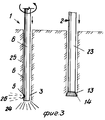
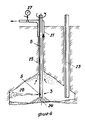
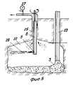
На фиг. 1 изображено устройство для возведения бетонной конструкции, вид спереди, в положении при выполнении земляных работ и до операции эрозии и цементирования; на фиг. 2 то же, вертикальный разрез с ходовой частью в виде транспортных гусениц; на фиг. 3 начальная эрозия полости (узел I на фиг. 1); на фиг. 4 расширение полости в результате эрозии; на фиг. 5 расширение полости по высоте с одновременной цементацией. In FIG. 1 shows a device for the erection of a concrete structure, front view, in position during excavation and before the operation of erosion and cementing; in FIG. 2 the same, a vertical section with the chassis in the form of transport caterpillars; in FIG. 3 initial erosion of the cavity (node I in Fig. 1); in FIG. 4 cavity expansion as a result of erosion; in FIG. 5 expansion of the cavity in height with simultaneous cementation.
Устройство для возведения бетонной конструкции включает рабочий орган, состоящий из эрозионного механизма 1 и цементирующего механизма 2 для цементации бетоном. Эрозионный механизм содержит эрозионную головку 3 с буровой коронкой 4, предусмотренной в самом низу. Над нею предусмотрено эрозионное сопло 5, которое представляет собой водяное сопло, которое окружено воздушным соплом для впрыскивания радиального струйного потока воды и воздуха. Эрозионный механизм содержит направляющую трубу 6, на которой смонтированы вышеупомянутые компоненты и через которую проходят водо- и воздуховоды для питания названных эрозионных сопел 5. Направляющая труба 6 установлена в подшипнике 7 с возможностью ее поднятия и опускания, а также с возможностью поворота, и на раме 8 предусмотрен вращающийся двигатель 9. Направляющая труба 6 на своем верхнем конце соединена с питающими трубопроводами 10 и 11 для воды и воздуха, соответственно, через шарнирное соединение 12. A device for erecting a concrete structure includes a working body, consisting of an
Цементирующий механизм 2 с цементирующей головкой 13 и буровой коронкой 14 установлен с возможностью вращения и поднятия, а также опускания в подшипнике 15, а вращающийся двигатель 16 предусмотрен на раме 17. Механизм 2 своим верхним концом соединен с питающим трубопроводом для бетона через шарнирное соединение 18. The
Рамы 8 и 17 образуют каркас 19 с установочными средствами 20, обеспечивающими взаимоотношением между рамами 8, 17. Каркас 19 предназначен для регулируемого соединения с тракторной гусеницей (фиг. 2) с помощью известных средств, обеспечивающих поднятие и опускание механизма, а также его наклон с помощью цилиндров сжатия известным самим по себе образом. Эрозионная головка 3 и цементирующая головка 13 могут, таким образом, приводиться в действие независимо для опускания, поднятия и вращения, соответственно. Рамы 8, 17 выполнены подвижными относительно друг друга для регулирования центрового расстояния между эрозионной головкой 3 и цементирующей головкой 13. Регулировочные средства состоят из регулировочных выдвижных штырей, которые соединяют рамы 8 и 17.
Буртик 21 предусмотрен около направляющей трубы 6 для того, чтобы собирать и направлять эродированный сыпучий материал из буровых полостей контролируемым образом через измеритель массы и плотности для обеспечения подсчета объема корродированной полости, т.е. расширенной полости. С помощью регулируемого распорного средства 20 межцентровое расстояние между эрозионной головкой 3 и цементирующей головкой 13 может регулироваться в соответствии с проектируемым диаметром расширенной буровой полости 22. A
Цементирующий механизм 2 содержит расширяющиеся цементирующие трубы 23. The
При осуществлении названного способа с помощью вышеупомянутого оборудования эрозионный механизм 1 и цементирующий механизм 2 врубаются вниз в породу или грунт с заданным межцентровым расстоянием между механизмами 1 и 2. Для установления хорошего контакта с породой применяется только направленное вниз эрозионное сопло 24 на эрозионной головке 3. При эрозии поверхности породы эрозионная головка 3 и направляющая труба 6 вытягиваются подъемными средствами (не показаны). Натягивание происходит медленно при постоянном вращении и одновременном выбросе сильно сжатой воды и воздуха под высоким давлением 100-1000 бар из водяного и воздушного сопла 5. Названная струя воды, покрытая воздухом, будет разбивать внизу структуру, состоящую из макрочастиц, и растворять почву в буровой полости 25, которая высверливается буровой коронкой 4 эрозионной головки 3. Таким образом, образуется расширенная буровая полость 22 с заданным диаметром, причем его диаметр может измеряться с помощью известного обоpудования, которое здесь подробно не описывается. Таким образом, создается цилиндрическая эродированная полость, которая составляет названную расширенную буровую полость 22. В силу избыточного давления, создаваемого струей 26 под высоким давлением из сопла 5, смываемый вниз материал будет выталкиваться к поверхности через буровую полость 25 и буртик 21. Одновременно или при установлении полости 22 через цементирующую трубу 23 цементирующей головкой 13 закачивается высокосортный бетон для заполнения полости 22, который будет выталкивать таким образом через буровую полость 25 материал, который опадал вниз в результате смывания. Бетон может быть предусмотрен с добавками, делающими его водоотталкивающим с тем, чтобы поток в полости 22, обусловленный эрозионной струей, вызывал минимальное вымывание связующего вещества из бетона. When implementing the above method using the above equipment, the
Когда направляющая труба 6 с эрозионной головкой 3 и цементирующая труба 23 с цементирующей головкой 13 натягиваются, цементирующая головка 13 должна предварительно быть установлена по меньшей мере на 0,5 м ниже сопла 5 для эрозионной струи, если последняя включается в действие с тем, чтобы уменьшить вредоносные потоки в эродированном пространстве, которые могут вымывать связующее вещество из бетона. When the guide pipe 6 with the
Буровая полость 25 образуется с помощью струи воздуха и воды до заданного уровня, в то время, когда вытягивается эрозионная головка 3, после чего эрозия прекращается. Цементирование полости 22 бетоном продолжается при одновременном затягивании цементирующей трубы 23 до тех пор, пока полость 22 не окажется заполненной, что проверяется с помощью эродированного материала, проталкиваемого через буровую полость 25. Когда полость полностью заполняется, такой материал заменяют выдавленным связующим веществом из цемента. The
Эрозионная головка 3 и цементирующая головка 12 забурены вниз на заданную глубину в грунт с обрабатывающей направленной вниз эрозионной струей 26 из эрозионной головки 3 для очищения породы. Когда эрозионная струя прекращается, из сопла 5 выпускается эрозионный стержень для расширения буровой полости 25 и образования расширенной полости 22 и, таким образом, заданной полости (фиг. 4), с заданным диаметром и заданной высотой (фиг. 5). The
На фиг. 4 показано начинающееся расширение буровой полости 25 при вращении и натягивании эрозионной головки 3, в то время как питающая труба 23 с цементирующей головкой 13 остается неподвижной в периферическом положении в нижней части расширенной буровой полости 22. In FIG. 4 shows the beginning expansion of the
На следующем этапе (фиг. 5) эрозионная головка 3 натягивается примерно до заданного уровня расширенной буровой полости 25, и на котором бетон подается через питающую трубу 23 до заполнения расширенной буровой полости 22. Эта операция продолжается до полного заполнения расширенной буровой полости 22. In the next step (Fig. 5), the
На фиг. 4 и 5 показаны расширенные буровые полости 22 с по существу круглым поперечным сечением и заданным диаметром, которые выполнены в цилиндрической структуре бетона. In FIG. 4 and 5 show enlarged
Заставляя эрозионную струю 26, т.е. воздушную и водяную, раскачиваться вперед и назад поперек сектора соответствующим вращением эрозионной головки 3, можно получить бетонную конструкцию с соответствующим поперечным сечением. Forcing the
Полным оборотом эрозионной головки 3 с одновременным контролем за эрозионным давлением воздушно-водяной струи можно получить, например овальные сваи, в зависимости от угла вращения вращающейся головки 3. A full revolution of the
Таким образом, при осуществлении способа эрозионную 3 и цементирующую 13 головки с буровыми коронками соответственно 4 и 14 при забуривании и подъеме перемещают одновременно, располагая их параллельно на заданном межцентровом расстоянии друг от друга со смещением цементирующей головки 13 вниз относительно эрозионной головки 3 и возможностью автономного вращения и осевого перемещения головок. При этом межцентровое расстояние могут регулировать перед забуриванием до требуемого радиуса расширенной полости. Thus, when implementing the method, the
Способ может осуществляться в грунте любого вида. Этот способ применим для глины, ила, песка и гравия, а также для большинства видов наполнителей, морены и болотистых торфяных почв. The method can be carried out in any type of soil. This method is applicable for clay, silt, sand and gravel, as well as for most types of fillers, moraines and marshy peat soils.
В связных грунтах способ эрозии и цементации, если желательно, может выполняться в две фазы, поскольку переходное напряжение в связных грунтах будет, как правило, предупреждать эродированную полость от обвала, если она заполнена водой. Несколько преимуществ осуществления способа эрозии и цементации в две операции:
1. Местный сыпучий материал предохраняется от смешивания с бетоном, поскольку цементация осуществляется подобно обычной заливке полости (обшивки досок) под водой;
2. Бетон в материале, возвращающемся через буровую полость 25, состоящем из эродированного материала и воды, добавленной из эрозионной струи 26, не содержится. Если объем и плотность возвращаемого вещества измеряется постоянно в измерителе 27 массы и плотности, который соединен с буртиком 21 в буровой полости 25, в этом случае можно рассчитать объем расширенной буровой полости 22. Высота Н возможная длина, если буровая полость 25 наклонная или горизонтальная расширенной буровой полости 25 всегда известна, можно высчитать среднее значение ее диаметра;
3. Можно составить точное картографирование протяженности расширенной буровой полости 22 с помощью акустической пробы, которая может быть опущена в полость 22. Благодаря систематическому вращению пробы, когда она вытягивается, можно определить полную ширину, обычно являющуюся диаметром.In cohesive soils, the method of erosion and cementation, if desired, can be performed in two phases, since the transient stress in cohesive soils will, as a rule, prevent the eroded cavity from collapsing if it is filled with water. Several advantages of the method of erosion and cementation in two operations:
1. Local bulk material is protected from mixing with concrete, since cementation is carried out similar to the usual filling of a cavity (plating boards) under water;
2. Concrete in the material returning through the
3. It is possible to make an accurate mapping of the length of the expanded
В грунте с большим коэффициентом трения обе операции, т.е. эрозия и цементация, должны проводиться одновременно, так как образованная полость 22 будет, как правило, обрушиваться до цементации бетоном. Расширенная буровая полость 22 может быть стабилизирована, если в полость вводить тяжелую стабилизирующую жидкость, например бентонит. Жидкость будет, однако, стремиться смешиваться с возвратным материалом, например, эродированными почвами и смывающей водой, в связи с чем протяженность, то есть ширина ствола сваи может измеряться только с помощью акустической пробы или путем измерения объема бетона, который заливается в полость 22. In the ground with a high coefficient of friction, both operations, i.e. erosion and cementation must be carried out simultaneously, since the formed
Уже упоминалось, что расстояние между эрозионной головкой 3 и цементирующей головкой 13 регулируется с помощью телескопических стержней в каркасе 19. Таким образом, можно обеспечить, чтобы цементирующая головка 13 и эрозионная головка 3 получили заданное взаимное межцентровое расстояние при врубании вниз в грунт, заставляя цементирующую головку 13 разместиться на периферии эродированного расширенной буровой полости 22. Таким образом, бетон, который впрыскивается через относительно толстую питающую трубу 23, будет заполнять расширенную буровую полость 22 из места на стенке полости и будет, таким образом, удалять любой эродированный материал и воду наружу через буровую полость 25. It has already been mentioned that the distance between the
Claims (4)
Applications Claiming Priority (3)
| Application Number | Priority Date | Filing Date | Title |
|---|---|---|---|
| NO890420A NO167051C (en) | 1989-02-02 | 1989-02-02 | PROCEDURE FOR THE ESTABLISHMENT OF CONCRETE CONSTRUCTIONS IN LOANS, FROM THE TERRACE LEVEL, AND EQUIPMENT FOR EXERCISING THE PROCEDURE |
| NO890420 | 1989-02-02 | ||
| PCT/NO1990/000025 WO1990008855A1 (en) | 1989-02-02 | 1990-02-01 | A process for building a concrete structure in loose matter, from ground level, and equipment for carrying out said process |
Publications (1)
| Publication Number | Publication Date |
|---|---|
| RU2042012C1 true RU2042012C1 (en) | 1995-08-20 |
Family
ID=19891690
Family Applications (1)
| Application Number | Title | Priority Date | Filing Date |
|---|---|---|---|
| SU915001470A RU2042012C1 (en) | 1989-02-02 | 1991-08-02 | Method of erection of concrete structure in loose material from ground level and device for erection of concrete structure in loose material from ground level |
Country Status (10)
| Country | Link |
|---|---|
| EP (1) | EP0457813B1 (en) |
| JP (1) | JP2532751B2 (en) |
| KR (1) | KR0174725B1 (en) |
| AU (1) | AU5090090A (en) |
| DE (1) | DE69002615T2 (en) |
| DK (1) | DK0457813T3 (en) |
| FI (1) | FI92506C (en) |
| NO (1) | NO167051C (en) |
| RU (1) | RU2042012C1 (en) |
| WO (1) | WO1990008855A1 (en) |
Families Citing this family (4)
| Publication number | Priority date | Publication date | Assignee | Title |
|---|---|---|---|---|
| FR2701973B1 (en) * | 1993-02-22 | 1995-04-07 | Sif | Airlock installation for soil treatment device by rotary jet (s). |
| US6957220B2 (en) | 2000-11-07 | 2005-10-18 | Research Investment Networks, Inc. | System, method and article of manufacture for tracking and supporting the distribution of content electronically |
| SE0202501L (en) * | 2002-08-23 | 2004-02-24 | Soilex Ab | Ways to make a pole and / or a tie rod |
| CN109441441B (en) * | 2018-11-15 | 2022-02-22 | 华北科技学院 | Simulation test device and method for coal seam bottom plate multi-angle inclined drilling grouting process under pressure-bearing flowing water action |
Family Cites Families (2)
| Publication number | Priority date | Publication date | Assignee | Title |
|---|---|---|---|---|
| FI65833C (en) * | 1977-12-27 | 1984-07-10 | Kajima Corp | SPRUTANORDNING FOER CEMENTVAELLING |
| SE444195B (en) * | 1982-08-16 | 1986-03-24 | Nit Co Ltd | A method and apparatus for the injection of solidifying material into a depth of soil |
-
1989
- 1989-02-02 NO NO890420A patent/NO167051C/en not_active IP Right Cessation
-
1990
- 1990-02-01 DE DE90903056T patent/DE69002615T2/en not_active Expired - Lifetime
- 1990-02-01 JP JP2503217A patent/JP2532751B2/en not_active Expired - Lifetime
- 1990-02-01 KR KR1019900701981A patent/KR0174725B1/en not_active IP Right Cessation
- 1990-02-01 WO PCT/NO1990/000025 patent/WO1990008855A1/en active IP Right Grant
- 1990-02-01 DK DK90903056.1T patent/DK0457813T3/en active
- 1990-02-01 AU AU50900/90A patent/AU5090090A/en not_active Abandoned
- 1990-02-01 EP EP90903056A patent/EP0457813B1/en not_active Expired - Lifetime
-
1991
- 1991-08-02 FI FI913689A patent/FI92506C/en active
- 1991-08-02 RU SU915001470A patent/RU2042012C1/en active
Non-Patent Citations (1)
| Title |
|---|
| Патент США N 3440824, кл. 405-267, 1969. * |
Also Published As
| Publication number | Publication date |
|---|---|
| FI92506C (en) | 1994-11-25 |
| FI913689A0 (en) | 1991-08-02 |
| EP0457813B1 (en) | 1993-08-04 |
| KR910700383A (en) | 1991-03-15 |
| KR0174725B1 (en) | 1999-02-18 |
| DE69002615D1 (en) | 1993-09-09 |
| NO167051C (en) | 1991-09-25 |
| DE69002615T2 (en) | 1993-11-11 |
| AU5090090A (en) | 1990-08-24 |
| FI92506B (en) | 1994-08-15 |
| EP0457813A1 (en) | 1991-11-27 |
| JPH07507362A (en) | 1995-08-10 |
| JP2532751B2 (en) | 1996-09-11 |
| NO167051B (en) | 1991-06-17 |
| DK0457813T3 (en) | 1993-12-27 |
| NO890420L (en) | 1990-08-03 |
| NO890420D0 (en) | 1989-02-02 |
| WO1990008855A1 (en) | 1990-08-09 |
Similar Documents
| Publication | Publication Date | Title |
|---|---|---|
| KR101067707B1 (en) | The earth retaining wall and waterproof construction technique for which cast in place concrete pile and grouting column was used | |
| CN101245600B (en) | Construction method for generating horizontal reinforcing body by high-pressure-double-liquid rotary spray technique | |
| CN104929114A (en) | High pressure jet grouting pile waterproof curtain construction device and method | |
| CN203452083U (en) | Rotary expanding pile construction equipment and grout feeding device | |
| CN107338789B (en) | A kind of construction method of down-the-hole percussion triple-pipe high pressure jet grouting stake | |
| CN204753574U (en) | High pressure jet grouting pile stagnant water curtain construction equipment | |
| CN113585289A (en) | Support method for collapse soil deep foundation pit | |
| CN1206417C (en) | Forming method for water-proof pile fender and screw drill therefor | |
| RU2042012C1 (en) | Method of erection of concrete structure in loose material from ground level and device for erection of concrete structure in loose material from ground level | |
| EP2319992A2 (en) | Method and system for placing at least one foundation element in the ground | |
| CN115961646A (en) | Foundation pit water stopping method in pebble stratum | |
| US11788249B2 (en) | Cutting tool adapter and method of underpinning structures using cutting tool adapter for soil mixing | |
| CN100485132C (en) | Formative method for row-pile style water-proof wall underground | |
| RU2013495C1 (en) | Method of levelling edifices constructions | |
| EP2009225B1 (en) | Method for providing a slab-shaped underground structure | |
| JP2958426B2 (en) | Differential settlement correction method | |
| JPH0442493B2 (en) | ||
| JPH0216813B2 (en) | ||
| JPS5826115A (en) | Expanded bottom pile work | |
| Bruce et al. | Pile Wall Cuts Off Seepage | |
| JPH0711644A (en) | Driving method of pile provided with bag at the front end | |
| CN117005391A (en) | Dry excavation pore-forming construction method for collapsible loess sand inclusion stratum pile foundation | |
| RU1776800C (en) | Method for plugging-up mine working while erecting antiseepage curtains | |
| CN108018849A (en) | A kind of shield launching and the construction method for reaching end soil body reinforcing | |
| JPH0522769B2 (en) |