RU2024943C1 - Graphic information read-out device - Google Patents
Graphic information read-out device Download PDFInfo
- Publication number
- RU2024943C1 RU2024943C1 SU915026440A SU5026440A RU2024943C1 RU 2024943 C1 RU2024943 C1 RU 2024943C1 SU 915026440 A SU915026440 A SU 915026440A SU 5026440 A SU5026440 A SU 5026440A RU 2024943 C1 RU2024943 C1 RU 2024943C1
- Authority
- RU
- Russia
- Prior art keywords
- output
- input
- pulse generator
- tablet
- block
- Prior art date
Links
- 230000015572 biosynthetic process Effects 0.000 claims description 10
- 238000007493 shaping process Methods 0.000 abstract 1
- 239000000126 substance Substances 0.000 abstract 1
- 230000010355 oscillation Effects 0.000 description 3
- 238000013016 damping Methods 0.000 description 2
- 230000005284 excitation Effects 0.000 description 2
- 238000006243 chemical reaction Methods 0.000 description 1
- 230000007423 decrease Effects 0.000 description 1
- 238000010586 diagram Methods 0.000 description 1
- 238000005516 engineering process Methods 0.000 description 1
- 238000005259 measurement Methods 0.000 description 1
- 230000001902 propagating effect Effects 0.000 description 1
Images
Landscapes
- Length Measuring Devices Characterised By Use Of Acoustic Means (AREA)
- Measurement Of Length, Angles, Or The Like Using Electric Or Magnetic Means (AREA)
Abstract
Description
Изобретение относится к автоматике и вычислительной технике и может быть использовано для считывания графической информации. The invention relates to automation and computer technology and can be used to read graphic information.
Известно устройство для считывания графической информации [1], содержащее первый и второй блоки формирования строб-импульсов и дополнительный пьезоэлектрический приемник, установленный на планшете, выходы пьезоэлектрических приемников подключены к управляющим входам соответствующих блоков формирования строб-импульсов, выход первого блока формирования строб-импульсов подключен к стробирующим входам формирователя возбуждающего напряжения, выход второго блока формирования строб-импульсов соединен с третьим и четвертым управляющими входами блока формирования временных интервалов, причем каждый из блоков формирования возбуждающего напряжения содержит трипер и ключ. A device for reading graphic information [1], containing the first and second blocks of the formation of strobe pulses and an additional piezoelectric receiver mounted on the tablet, the outputs of the piezoelectric receivers are connected to the control inputs of the respective blocks of the formation of strobe pulses, the output of the first block of the formation of strobe pulses is connected to the gate inputs of the driver of the exciting voltage, the output of the second block forming the strobe pulses is connected to the third and fourth control the inputs of the block forming the time intervals, and each of the blocks forming the exciting voltage contains a tripper and a key.
Недостатками данного устройства являются трудность получения на дополнительных пьезоэлектрических пластинках сигнала, соответствующего уровню демпфируемого сигнала, и практической невозможностью получения соответствующей формы сигнала, что приводит к неполному демпфированию этой волны и наличию отраженных сигналов в планшете и малой точности и быстродействия устройства. The disadvantages of this device are the difficulty in obtaining additional piezoelectric plates of the signal corresponding to the level of the damped signal, and the practical impossibility of obtaining the corresponding waveform, which leads to incomplete damping of this wave and the presence of reflected signals in the tablet and low accuracy and speed of the device.
Наиболее близким к предлагаемому является ультразвуковой координатометр [2] , содержащий планшет с установленными на его сторонах пьезоэлектрическими пластинами, попарно подключенными на перпендикулярных сторонах планшета к первому и второму выходам генератора импульсов непосредственно и через первый и второй блоки формирования возбуждающего напряжения соответственно, блок формирования временных интервалов; третий и четвертый входы которого подключены к третьему и четвертому выходам генератора импульсов, съемник координат. Closest to the proposed one is an ultrasonic coordinate gauge [2], containing a tablet with piezoelectric plates mounted on its sides, pairwise connected on the perpendicular sides of the tablet to the first and second outputs of the pulse generator directly and through the first and second excitation voltage generation blocks, respectively, a time interval formation block ; the third and fourth inputs of which are connected to the third and fourth outputs of the pulse generator, coordinate remover.
Недостатками данного устройства являются следующие: волны, возбуждаемые в планшете представляют собой сумму бесконечного числа нормальных волн (симметричных и несимметричных), образующих продольные и сдвиговые волны с разными фазовыми скоростями (см. Микер Т., Мейстер А., Волноводные распространения в протяженных цилиндрах и пластинках. - В кн.: Физическая акустика под ред. У.Мейзона, Т 1А). Поэтому в точке расположения дополнительной пьезопластины возникает сложная интерференционная картина и наблюдается сильное искажение формы и фазы колебаний, причем первые несколько полуволн (до момента прихода сдвиговой волны) имеют малую амплитуду и синусоидальную форму, а последующие - большую амплитуду и искаженную форму. Вследствие этого при подаче напряжения на дополнительные пьезопластины происходит лишь частичное демпфирование продольной волны в точке, а начиная с момента прихода сдвиговой волны, колебания практически не демпфируются, так как невозможно получить такую амплитуду и фазу сигнала, который бы полностью демпфировал все составляющие ультразвукового поля в планшете. Так как амплитуда искаженных колебаний больше амплитуды продольной волны, то время затухания волн в планшете уменьшается незначительно, и, как следствие, частота переключения также увеличивается незначительно. Поэтому точность при динамических измерениях также увеличивается незначительно, что недостаточно при считывании графической информации. The disadvantages of this device are as follows: the waves excited in the tablet are the sum of an infinite number of normal waves (symmetric and asymmetric), forming longitudinal and shear waves with different phase velocities (see Miker T., Meister A., Waveguide propagations in extended cylinders and records. - In the book: Physical Acoustics under the editorship of W. Meyson, T 1A). Therefore, at the point of location of the additional piezoelectric plate, a complex interference pattern arises and a strong distortion of the shape and phase of the oscillations is observed, the first few half-waves (before the arrival of the shear wave) have a small amplitude and a sinusoidal shape, and the subsequent ones have a large amplitude and a distorted shape. As a result of this, when voltage is applied to additional piezoelectric plates, only a partial damping of the longitudinal wave occurs at the point, and starting from the moment the shear wave arrives, the oscillations practically do not damp, since it is impossible to obtain such an amplitude and phase of the signal that would completely damp all components of the ultrasonic field in the tablet . Since the amplitude of the distorted oscillations is greater than the amplitude of the longitudinal wave, the attenuation time of the waves in the tablet decreases slightly, and, as a result, the switching frequency also increases slightly. Therefore, the accuracy in dynamic measurements also increases slightly, which is not enough when reading graphic information.
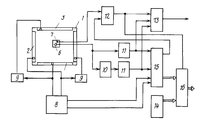
На чертеже приведена функциональная схема устройства для считывания графической информации. The drawing shows a functional diagram of a device for reading graphic information.
Устройство содержит квадратный планшет 1, первую 2, вторую 3, третью 4 и четвертую 5 пьезоэлектрические пластины, пьезоэлектрический приемник 6, переключатель 7, генератор импульсов 8, блоки формирования возбуждающего напряжения 9, аналоговый инвертор 10, блоки формирования строб-импульсов 11, элемент И 12, элемент ИЛИ 13, блок формирования временных координатных интервалов 15, блок кодовых переключателей 14 и мультиплексор 16. The device comprises a square tablet 1, first 2, second 3, third 4 and fourth 5 piezoelectric plates,
Генератор импульсов 8 соединен с первой 2 и третьей 4 пьезоэлектрическими пластинами, с блоками формирования возбуждаемого напряжения 9, выходы которых подключены к второй 3 и четвертой 5 пьезоэлектрическим пластинам и с блоком формирования временных координатных интервалов 15. Пьезоэлектрический приемник 6 подключен к блокам формирования строб-импульсов 11, к первому непосредственно блоков 11 соединены с блоком 15 и с входами элемента ИЛИ 13. Входы элемента И 12 соединены с переключателем 7 и с управляющим выходом блока 15, а выход с третьим входом блока 13 и с управляющим входом мультиплексора 16, информационные входы которого подключены к информационным выходам блоков 14 и 15. The
Устройство работает следующим образом. Генератор импульсов 8 со сдвигом во времени, определяемым временем пробега волны до середины планшета, попеременно возбуждает ультразвуковые волны по координатным осям Х и Y, причем возбуждаются в одних (2, 4) пьезоэлектрических пластинках волны одной полярности, а в других (3, 5) - волны обратной полярности. Упругие бегущие волны противоположных полярностей распространяются по планшету 1 вдоль координатных осей навстречу друг другу с постоянной скоростью. При установке приемника 6 на поверхность планшета в точке сканирования через время, соответствующее расстоянию пробега фронта бегущей волны от ближайшей пьезоэлектрической пластины до места контакта приемника 6 с поверхностью планшета 1, приемник начинает формировать электрический сигнал, полярность которого соответствует полярности принимаемого фронта бегущей волны, и в зависимости от его полярности срабатывает первый (если сигнал положительной полярности) или же второй (если сигнал отрицательной полярности) блок формирования строб-импульсов и сформирует одиночный импульс, который поступает в блок формирования временных координатных интервалов 15, который представляет собой вычислительный блок и осуществляет соответствующий пересчет координат в зависимости от полярности регистрируемой волны, которая определяет нахождение измеряемой точки на той или иной половине планшета по отношению к измеряемой оси координат в данный момент. The device operates as follows. A
Бегущие противополярные волны, распространяющиеся вдоль измеряемой оси навстречу, встречаются точно в середине планшета и полностью демпфируются там же. При установке приемника 6 точно в середине планшета сигналы не поступают на блоки 11 и происходит переполнение внутреннего счетчика блока 15 (не показан) и сигнал переполнения счетчика вместе с сигналом от переключателя, который выдает сигнал о том, что идет считывание координат, поступают на элемент И 12 его выходной, а сигнал, подаваемый на мультиплексор 16, пропускает код, соответствующий координате измеряемой точки с блока 14 на информационный выход устройства. Блок 14 представляет собой группу кодовых переключателей, с помощью которых задается постоянный код и устанавливается вручную. Running antipolar waves propagating towards the measured axis meet exactly in the middle of the tablet and are completely damped there. When the
Элемент ИЛИ 13 формирует синхросигнал для передачи кода координаты по сигналу от первого или второго блока 11, или же от блока 12. The OR element 13 generates a clock signal for transmitting a coordinate code according to a signal from the first or
Claims (1)
Priority Applications (1)
| Application Number | Priority Date | Filing Date | Title |
|---|---|---|---|
| SU915026440A RU2024943C1 (en) | 1991-12-05 | 1991-12-05 | Graphic information read-out device |
Applications Claiming Priority (1)
| Application Number | Priority Date | Filing Date | Title |
|---|---|---|---|
| SU915026440A RU2024943C1 (en) | 1991-12-05 | 1991-12-05 | Graphic information read-out device |
Publications (1)
| Publication Number | Publication Date |
|---|---|
| RU2024943C1 true RU2024943C1 (en) | 1994-12-15 |
Family
ID=21596441
Family Applications (1)
| Application Number | Title | Priority Date | Filing Date |
|---|---|---|---|
| SU915026440A RU2024943C1 (en) | 1991-12-05 | 1991-12-05 | Graphic information read-out device |
Country Status (1)
| Country | Link |
|---|---|
| RU (1) | RU2024943C1 (en) |
-
1991
- 1991-12-05 RU SU915026440A patent/RU2024943C1/en active
Non-Patent Citations (2)
| Title |
|---|
| 1. Авторское свидетельство СССР N 1425735, кл. G 06K 11/00, 1988. * |
| 2. Авторское свидетельство СССР N 881900, кл. H 01L 41/08, 1981. * |
Similar Documents
| Publication | Publication Date | Title |
|---|---|---|
| JP3022623B2 (en) | Electrical measuring device for measuring signal propagation time | |
| EP0358904A3 (en) | Method and system for dual phase scanning acoustic microscopy | |
| KR920021999A (en) | System and method for detecting weak points of structures | |
| US4894806A (en) | Ultrasonic imaging system using bundle of acoustic waveguides | |
| CA1103489A (en) | Digital type ultrasonic holography apparatus | |
| RU2024943C1 (en) | Graphic information read-out device | |
| RU2018958C1 (en) | Device for reading graphical information out | |
| US3360769A (en) | Method and means for generating and analyzing special waveform signals of high information content | |
| US5798597A (en) | Surface acoustic wave device for sensing a touch-position | |
| RU2039929C1 (en) | Ultrasonic displacement transducer | |
| DE58909035D1 (en) | METHOD AND DEVICE FOR MEASURING TWO-DIMENSIONAL REFLECTIVE STRUCTURES. | |
| RU2025779C1 (en) | Device for reading of graphical information | |
| SU1425735A1 (en) | Device for reading graphic information | |
| SU1504509A1 (en) | Ultrasonic self-calibrating meter of linear dimensions and displacements | |
| SU1458856A1 (en) | Device for measuring short time intervals | |
| RU2024942C1 (en) | Graphic information read-out device | |
| RU2039930C1 (en) | Ultrasonic displacement transducer | |
| JPS6133523A (en) | Position orienting device utilizing elastic wave | |
| SU1203557A1 (en) | Device for reading graphic information | |
| SU1067370A1 (en) | Device for measuring plate vibration parameters | |
| SU1397830A1 (en) | Apparatus for ultrasonic inspection of materials and articles | |
| SU1191732A1 (en) | Device for checking angular displacements | |
| JPS6330924A (en) | Coordinate input device utilizing elastic wave | |
| SU1113816A1 (en) | Device for solving boundary-value problems | |
| Harris et al. | Practical properties of a thick-film elastic wave sensor structure |