RU2024942C1 - Graphic information read-out device - Google Patents
Graphic information read-out device Download PDFInfo
- Publication number
- RU2024942C1 RU2024942C1 SU5026373A RU2024942C1 RU 2024942 C1 RU2024942 C1 RU 2024942C1 SU 5026373 A SU5026373 A SU 5026373A RU 2024942 C1 RU2024942 C1 RU 2024942C1
- Authority
- RU
- Russia
- Prior art keywords
- inputs
- output
- outputs
- input
- elements
- Prior art date
Links
- 238000009434 installation Methods 0.000 claims description 7
- 239000000126 substance Substances 0.000 abstract 1
- 230000036039 immunity Effects 0.000 description 3
- 239000000523 sample Substances 0.000 description 3
- 230000035945 sensitivity Effects 0.000 description 3
- 238000010835 comparative analysis Methods 0.000 description 1
- 230000000368 destabilizing effect Effects 0.000 description 1
- 238000010586 diagram Methods 0.000 description 1
- 230000008030 elimination Effects 0.000 description 1
- 238000003379 elimination reaction Methods 0.000 description 1
- 230000010355 oscillation Effects 0.000 description 1
- 230000001960 triggered effect Effects 0.000 description 1
Images
Landscapes
- Measurement Of Velocity Or Position Using Acoustic Or Ultrasonic Waves (AREA)
Abstract
Description
Изобретение относится к автоматике и вычислительной технике и может быть использовано для считывания графической информации. The invention relates to automation and computer technology and can be used to read graphic information.
Известно устройство ввода графической информации [1], содержащее подвижный электроакустический преобразователь, связанный со схемой управления, приемники акустических колебаний, расположенные под прямым углом друг к другу и подключенные через времяимпульсные преобразователи к входам соответствующих счетчиков координат, генератор тактовых импульсов, соединенный с одним из входов времяимпульсных преобразователей, а другие входы которых связаны с электроакустическим преобразователем, отличающееся тем, что, с целью повышения точности определения координат изображения, оно содержит дополнительный электроакустический преобразователь, подключенный к дополнительному входу одного из времяимпульсных преобразователей, блок постоянной памяти, дешифратор, последовательно соединенные блок вычитания кодов, сумматор и преобразователь код-напряжение, выход которого подключен к управляющему входу генератора тактовых импульсов, а разрядные выходы блока постоянной памяти соединены с входами блока вычитания кодов, выход которого подключен к входам сумматора и через дешифратор к схеме управления. A device for inputting graphic information [1] is known, which contains a movable electro-acoustic transducer associated with a control circuit, acoustic oscillation receivers located at right angles to each other and connected via time-pulse converters to the inputs of the respective coordinate counters, a clock generator connected to one of the inputs time-pulse converters, and other inputs of which are connected with an electro-acoustic transducer, characterized in that, in order to improve accuracy determining the coordinates of the image, it contains an additional electro-acoustic transducer connected to an additional input of one of the time-pulse converters, a constant memory unit, a decoder, series-connected codes subtraction unit, an adder and a code-voltage converter, the output of which is connected to the control input of a clock pulse generator, and bit the outputs of the read-only memory block are connected to the inputs of the code subtraction unit, the output of which is connected to the inputs of the adder through decryptor p to the control scheme.
Недостатком данного устройства является невысокая помехоустойчивость, обусловленная тем, что любая помеха, попадающая в предел чувствительности усилителя, может регистрироваться как полезный сигнал. The disadvantage of this device is its low noise immunity, due to the fact that any interference falling within the sensitivity limit of the amplifier can be recorded as a useful signal.
Известно также устройство для считывания графической информации [2], содержащее планшет-звукопровод, на взаимно перпендикулярных сторонах которого установлены пьезоэлектрические излучатели, съемник координат, выход которого подключен к входу усилителя, первый элемент И, один из входов которого является входом устройства, а выход соединен с входами первого и второго формирователей сигналов, выходы которых соединены соответственно с входами первого элемента ИЛИ, с входами пьезоэлектрических преобразователей и одним из входов первого и второго триггеров, другие входы которых подключены к выходам второго и третьего элементов ИЛИ, генератор импульсов, выход которого соединен с другими входами первого элемента И и одним из входов второго и третьего элементов И, выходы которых подключены к информационным входам счетчиков, управляющие входы которых соединены с первыми входами второго и третьего элементов ИЛИ и с входом устройства, выходом которого является один из выходов счетчиков, другие выходы которых подключены к вторым входам второго и третьего элементов ИЛИ, отличающееся тем, что, с целью повышения надежности, оно содержит третий и четвертый формирователи сигналов, входы которых соединены с выходом усилителя, четвертый, пятый и шестой элементы ИЛИ, третий триггер и последовательно соединенные четвертый элемент И и второй одновибратор, выход которого подключен к первым входам пятого и шестого элементов ИЛИ, вторые входы которых соединены соответственно с выходами четвертого и второго триггеров, а выходы подключены к другим входам второго и третьего элементов И, выходы третьего и четвертого формирователей сигналов соединены с выходами четвертого элемента ИЛИ, выход которого подключен к третьим входам второго и третьего элементов ИЛИ, выход первого элемента ИЛИ соединен с одним из входов третьего триггера, другой вход которого подключен к выходу четвертого формирователя сигналов, а выход - к одному из входов четвертого элемента И, другой вход которого соединен с выходом третьего формирователя сигналов. It is also known a device for reading graphic information [2], containing a tablet-sound pipe, on the mutually perpendicular sides of which there are piezoelectric emitters, a coordinate puller, the output of which is connected to the input of the amplifier, the first element And, one of the inputs of which is the input of the device, and the output is connected with the inputs of the first and second signal conditioners, the outputs of which are connected respectively to the inputs of the first OR element, with the inputs of the piezoelectric transducers and one of the inputs of the first and second triggers, the other inputs of which are connected to the outputs of the second and third elements OR, a pulse generator, the output of which is connected to other inputs of the first element AND and one of the inputs of the second and third elements AND, the outputs of which are connected to information inputs of meters, the control inputs of which are connected to the first inputs of the second and third elements OR and with the input of the device, the output of which is one of the outputs of the counters, the other outputs of which are connected to the second inputs of the second and third elements OR it consists in that, in order to increase reliability, it contains the third and fourth signal conditioners, the inputs of which are connected to the output of the amplifier, the fourth, fifth and sixth elements of OR, the third trigger and the fourth element And in series, and the second one-shot, the output of which is connected to the first the inputs of the fifth and sixth elements OR, the second inputs of which are connected respectively to the outputs of the fourth and second triggers, and the outputs are connected to other inputs of the second and third elements And, the outputs of the third and fourth Signals are connected to the outputs of the fourth OR element, the output of which is connected to the third inputs of the second and third OR elements, the output of the first OR element is connected to one of the inputs of the third trigger, the other input of which is connected to the output of the fourth signal conditioner, and the output to one of the inputs the fourth element And, the other input of which is connected to the output of the third signal conditioner.
Недостатком данного устройства является невысокая точность, так как оно не устраняет погрешности, вызванной изменением амплитуды сигнала на выходе съемника координат ввиду нестабильности его контакта с поверхностью планшета-звукопровода и затуханием ультразвуковой волны в звукопроводе по мере ее удаления от излучателя. The disadvantage of this device is its low accuracy, since it does not eliminate the error caused by a change in the amplitude of the signal at the output of the coordinate pickup due to the instability of its contact with the surface of the tablet sound duct and the attenuation of the ultrasonic wave in the sound duct as it moves away from the emitter.
Наиболее близким к предлагаемому является устройство для считывания графической информации [3] , содержащее планшет-звукопровод, на взаимно перпендикулярных сторонах которого установлены пьезоэлектрические излучатели, съемник координат, выход которого подключен к входу усилителя, первый элемент И, один из входов которого является входом устройства и соединен с первыми входами первого и второго элементов ИЛИ и с установочными входами первого и второго счетчиков, выходы которых являются выходами устройства, а информационные входы подключены соответственно к выходам второго и третьего элементов И, первые входы которых и другой вход первого элемента И соединены с выходом генератора импульсов, выход первого элемента И подключен к входу одновибратора, выход которого соединен с входами первого и второго формирователей сигналов, выходы которых подключены соответственно к входам пьезоэлектрических излучателей и одним из установочных входов первого и второго триггеров, другие установочные входы которых соединены соответственно с выходами первого и второго элементов ИЛИ, вторые входы которых подключены к другим выходам первого и второго счетчиков соответственно, фазовращатель, компаратор и третий формирователь сигналов, выход которого подключен к третьим входам первого и второго элементов ИЛИ, выходы усилителя и фазовращателя соединены с информационными входами компаратора, а выходы первого и второго триггеров подключены соответственно к вторым входам второго и третьего элементов И. Closest to the proposed one is a device for reading graphic information [3], containing a tablet-sound pipe, on the mutually perpendicular sides of which there are piezoelectric emitters, a coordinate puller, the output of which is connected to the input of the amplifier, the first element And, one of the inputs of which is the input of the device and connected to the first inputs of the first and second elements OR and to the installation inputs of the first and second counters, the outputs of which are the outputs of the device, and the information inputs are connected correspondingly to the outputs of the second and third elements And, the first inputs of which and the other input of the first element And are connected to the output of the pulse generator, the output of the first element And is connected to the input of the one-shot, the output of which is connected to the inputs of the first and second signal conditioners, the outputs of which are connected respectively to the inputs of the piezoelectric emitters and one of the installation inputs of the first and second triggers, the other installation inputs of which are connected respectively to the outputs of the first and second elements OR, the second inputs of which are connected to the other outputs of the first and second counters, respectively, a phase shifter, a comparator and a third signal conditioner, the output of which is connected to the third inputs of the first and second elements OR, the outputs of the amplifier and phase shifter are connected to the information inputs of the comparator, and the outputs of the first and second triggers are connected respectively, to the second inputs of the second and third elements I.
Недостатком данного устройства является то, что любая помеха, независимо от ее уровня, попадающая в предел чувствительности усилителя, может регистрироваться вместо полезного сигнала, что делает устройство помехозащищенным. The disadvantage of this device is that any interference, regardless of its level, falling within the sensitivity limit of the amplifier, can be recorded instead of a useful signal, which makes the device noise-immune.
Предлагается устройство для считывания графической информации, содержащее планшет-звукопровод, на взаимно перпендикулярных сторонах которого установлены пьезоэлектрические излучатели, съемник координат, выход которого подключен к входу усилителя, первый элемент И, один из входов которого является входом устройства и соединен с первыми входами первого и второго элементов ИЛИ и с установленными входами первого и второго счетчиков, выходы которых являются выходами устройства, а выходам второго и третьего элементов И, первые входы которых и другой вход первого элемента И соединены с выходом генератора импульсов, выход первого элемента И подключен к входу одновибратора, выход которого соединен с входами первого и второго формирователей сигналов, выходы которых подключены соответственно к входам пьезоэлектрических излучателей и одним из установочных входов первого и второго триггеров, другие установочные входы которых соединены соответственно с выходами первого и второго элементов ИЛИ, вторые входы которых подключены к другим выходам первого и второго счетчиков соответственно, третий формирователь сигналов, фазовращатель и компаратор, выход третьего формирователя сигналов подключен к третьим входам первого и второго элементов ИЛИ, выходы усилителя и фазовращателя соединены с входами компаратора, а выходы первого и второго триггеров подключены соответственно к вторым входам второго и третьего элементов И, селектор длительности, вход которого подключен к выходу компаратора, а выход - к входу третьего формирователя сигналов. A device is proposed for reading graphic information containing a tablet-sound pipe, on the mutually perpendicular sides of which there are piezoelectric emitters, a coordinate puller, the output of which is connected to the input of the amplifier, the first element And, one of the inputs of which is the input of the device and connected to the first inputs of the first and second OR elements with installed inputs of the first and second counters, the outputs of which are the outputs of the device, and the outputs of the second and third elements of AND, the first inputs of which s and the other input of the first element And are connected to the output of the pulse generator, the output of the first element And is connected to the input of a single vibrator, the output of which is connected to the inputs of the first and second signal conditioners, the outputs of which are connected respectively to the inputs of the piezoelectric emitters and one of the installation inputs of the first and second triggers other installation inputs of which are connected respectively to the outputs of the first and second elements OR, the second inputs of which are connected to other outputs of the first and second counters, respectively Accordingly, the third signal driver, phase shifter and comparator, the output of the third signal driver is connected to the third inputs of the first and second OR elements, the outputs of the amplifier and phase shifter are connected to the comparator inputs, and the outputs of the first and second triggers are connected respectively to the second inputs of the second and third elements And, duration selector, the input of which is connected to the output of the comparator, and the output to the input of the third signal conditioner.
Сопоставительный анализ показывает, что предлагаемое устройство от прототипа действительно отличается новыми элементами и связями, поэтому заявленное устройство соответствует критерию изобретения "Новизна". Comparative analysis shows that the proposed device from the prototype is really different in new elements and relationships, therefore, the claimed device meets the criteria of the invention of "Novelty."
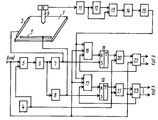
На чертеже приведена функциональая схема устройства для считывания графической информации. The drawing shows a functional diagram of a device for reading graphic information.
Устройство содержит планшет-звукопровод 1, две пьезоэлектрические пластины 2, 3 установлены на взаимно перпендикулярных сторонах планшета, генератор импульсов 4, первый 5, второй 20 и третий 21 элементы И, одновибратор 6, первый 7, второй 8 и третий 15 формирователи сигналов, щуп 9, пьезоэлектрический приемник 10, усилитель 11, фазовращатель 12, компаратор 13, селектор длительности 14, формирователь импульсов 15, первый 16 и второй 17 элементы ИЛИ, первый 18 и второй 19 триггеры и первый 22 и второй 23 счетчики. The device contains a tablet-
Пьезоэлектрические пластины 2 и 3, соединенные соответственно с выходами формирователей сигналов 7 и 8, входы которых подключены к выходу одновибратора 6, вход которого подключен к выходу элемента И 5, первый вход которого является входом устройства и соединен с установочными входами счетчиков 22 и 23.
Выход генератора импульсов 4 подключен ко второму входу элемента И 5, к входам элементов ИЛИ 16 и 17 и к входам элементов И 20 и 21, первые входы которых соединены соответственно с выходами триггеров 18 и 19, входы S которых подключены к выходам формирователей сигналов 7 и 8, а входы R которых - к выходам элементов ИЛИ 16 и 17. The output of the
Входы счета счетчиков 22 и 23 соединены с выходами элементов И 20 и 21, а информационные выходы являются выходами устройства. The inputs of the
Пьезоэлектрический приемник 10, приклеенный к щупу 9, подключен к входу усилителя 11, выход которого соединен с входами фазовращателя 12 и компаратора 13, первый вход которого подключен к выходу фазовращателя 12. Выход компаратора 13 соединен с первыми входами элементов ИЛИ 16 и 17 через последовательно соединенные селектор длительности 14 и формирователь импульсов 15, третьи входы которых подключены к выходам переполнения соответствующих счетчиков 22 и 23. The
Устройство работает следующим образом. Рассмотрим работу устройства при измерении какой-нибудь координаты - например Х. При появлении импульса на входе устройства синхронно с импульсом генератора 4 срабатывает одновибратор 6, а также устанавливаются в нулевое состояние счетчики 22 и 23 и через элементы ИЛИ 16 и 17 триггеры 18 и 19. По переднему фронту импульса с выхода одновибратора формируется короткий импульс в формирователе 7, который поступает на излучатель 2, и в планшете 1 вдоль координаты Х начинает распространяться плоская бегущая ультразвуковая волна. Одновременно передний фронт этого импульса взводит триггер 18, формируя передний фронт временного интервала. The device operates as follows. Consider the operation of the device when measuring some coordinate - for example, X. When a pulse appears at the input of the device, the one-shot 6 is triggered synchronously with the pulse of the
Как только фронт бегущей волны достигает щупа 9, в пьезоприемнике 10 возбуждается электрический сигнал, который усилителем 11 и поступает на один из входов компаратора 13, на другой вход которого подается такой же по амплитуде, но сдвинутый по фазе, сигнал с выхода фазовращателя 12. В момент времени, когда сигнал U2 на входе компаратора 13 превышает сигнал U1, на другом входе на величину Uп, определяемую чувствительностью компаратора, на выходе компаратора 13 формируется потенциал высокого уровня U3, который сохраняется до тех пор, пока уровень U2 не станет меньше U1 на величину Мп, формируя при этом импульс длительности τна выходе компаратора в точке U3. Если τ= τп , где τп - длительность, на которую настроен селектор длительности 14, то на выходе его формируется сигнал, который при поступлении на вход формирователя импульсов 15, на выходе его формируется короткий сигнал, который через элемент ИЛИ 16 сбрасывает триггер 18, формируя задний фронт временного координатного интервала.As soon as the front of the traveling wave reaches the probe 9, an electric signal is excited in the
На временной интервал, формируемый триггером 18, открывается элемент И 20, разрешая счет в счетчике 22, который формирует код соответствующий координате Х. At the time interval formed by the trigger 18, the And
Устройство позволяет регистрировать моменты прихода ультразвуковой волны в приемник с устранением погрешности, связанной с нестабильностью ее амплитуды, в результате наличия дестабилизирующих факторов (таких как нестабильность усилия прижатия шипа к планшету). Это обеспечивается применением компаратора с переменным порогом сравнения. The device allows you to record the moments of arrival of the ultrasonic wave in the receiver with the elimination of the error associated with the instability of its amplitude, as a result of the presence of destabilizing factors (such as the instability of the force of pressing the tenon to the tablet). This is ensured by the use of a comparator with a variable comparison threshold.
Устройство также устраняет возможность регистрации помех вместо полезного сигнала, так как помеха не может иметь ту же длительность сигнала U3 на выходе компаратора 13, что имеет сам полезный сигнал. Длительность этого сигнала регистрируется селектором длительности 14.The device also eliminates the possibility of registering interference instead of a useful signal, since the interference cannot have the same signal duration U 3 at the output of the
Приведем доказательство повышения помехоустойчивости устройства. В прототипе регистрируется любой поступающий сигнал с выхода усилителя независимо от того, что он является полезным или же помехой. Полезный сигнал отличается от помехи тем, что он независимо от его амплитуды формирует выходной сигнал компаратора, который является постоянным по длительности. Введение селектора длительности обеспечивает игнорирование помех и регистрацию полезного сигнала независимо от наличия помех. Here is the evidence of increasing the noise immunity of the device. In the prototype, any incoming signal from the output of the amplifier is recorded, regardless of whether it is useful or interference. A useful signal differs from interference in that it, regardless of its amplitude, generates an output signal from the comparator, which is constant in duration. The introduction of a duration selector ensures that interference is ignored and a useful signal is recorded regardless of the presence of interference.
Таким образом, по сравнению с базовым объектом, в предлагаемом устройстве обеспечивается значительное повышение помехоустойчивости. Thus, compared with the base object, the proposed device provides a significant increase in noise immunity.
Claims (1)
Priority Applications (1)
| Application Number | Priority Date | Filing Date | Title |
|---|---|---|---|
| SU5026373 RU2024942C1 (en) | 1991-12-29 | 1991-12-29 | Graphic information read-out device |
Applications Claiming Priority (1)
| Application Number | Priority Date | Filing Date | Title |
|---|---|---|---|
| SU5026373 RU2024942C1 (en) | 1991-12-29 | 1991-12-29 | Graphic information read-out device |
Publications (1)
| Publication Number | Publication Date |
|---|---|
| RU2024942C1 true RU2024942C1 (en) | 1994-12-15 |
Family
ID=21596408
Family Applications (1)
| Application Number | Title | Priority Date | Filing Date |
|---|---|---|---|
| SU5026373 RU2024942C1 (en) | 1991-12-29 | 1991-12-29 | Graphic information read-out device |
Country Status (1)
| Country | Link |
|---|---|
| RU (1) | RU2024942C1 (en) |
-
1991
- 1991-12-29 RU SU5026373 patent/RU2024942C1/en active
Non-Patent Citations (3)
| Title |
|---|
| 1. Авторское свидетельство СССР N 488231, кл. G 06K 11/06, 1975. * |
| 2. Авторское свидетельство СССР N 1196921, кл. G 06K 11/06, 1985. * |
| 3. Авторское свидетельство СССР N 1439641, кл. G 06K 11/06, 1988. * |
Similar Documents
| Publication | Publication Date | Title |
|---|---|---|
| US5142506A (en) | Ultrasonic position locating method and apparatus therefor | |
| JP3022623B2 (en) | Electrical measuring device for measuring signal propagation time | |
| US5379269A (en) | Position determining apparatus | |
| US3692936A (en) | Acoustic coordinate data determination system | |
| US5050134A (en) | Position determining apparatus | |
| US5009277A (en) | Method and apparatus for position determination | |
| RU2024942C1 (en) | Graphic information read-out device | |
| KR950001281A (en) | Obstacle distance measuring device using ultrasonic sensor and method | |
| EP0107922A1 (en) | Graphical data apparatus | |
| SU932098A1 (en) | Discrete apparatus for locating pressure pipeline damages | |
| RU2025778C1 (en) | Device for reading of graphical information | |
| SU954857A1 (en) | Device for determination of friction pair run-in completion time | |
| JPH05825Y2 (en) | ||
| SU963014A2 (en) | Graphic information readout device | |
| CN114167424B (en) | Sound wave distance measuring method, device and system | |
| RU2025779C1 (en) | Device for reading of graphical information | |
| RU2104482C1 (en) | Magnetostrictive converter of movements | |
| RU2039929C1 (en) | Ultrasonic displacement transducer | |
| SU1059587A1 (en) | Device for graphic information readout | |
| SU1088033A1 (en) | Device for converting coordinates of points of graphic image to electric signals | |
| RU2006793C1 (en) | Ultrasound converter of linear movements | |
| SU881788A1 (en) | Device for reading-out graphic information | |
| SU866410A2 (en) | Magnetostriction displacement transducer | |
| SU777850A1 (en) | Magnetostriction displacement sensor | |
| RU2024943C1 (en) | Graphic information read-out device |