RU196698U1 - ELECTRIC PNEUMATIC BRAKE OF THE FREIGHT WAGON - Google Patents
ELECTRIC PNEUMATIC BRAKE OF THE FREIGHT WAGON Download PDFInfo
- Publication number
- RU196698U1 RU196698U1 RU2019120939U RU2019120939U RU196698U1 RU 196698 U1 RU196698 U1 RU 196698U1 RU 2019120939 U RU2019120939 U RU 2019120939U RU 2019120939 U RU2019120939 U RU 2019120939U RU 196698 U1 RU196698 U1 RU 196698U1
- Authority
- RU
- Russia
- Prior art keywords
- controller
- brake
- electro
- pneumatic brake
- valve
- Prior art date
Links
Images
Classifications
-
- B—PERFORMING OPERATIONS; TRANSPORTING
- B60—VEHICLES IN GENERAL
- B60T—VEHICLE BRAKE CONTROL SYSTEMS OR PARTS THEREOF; BRAKE CONTROL SYSTEMS OR PARTS THEREOF, IN GENERAL; ARRANGEMENT OF BRAKING ELEMENTS ON VEHICLES IN GENERAL; PORTABLE DEVICES FOR PREVENTING UNWANTED MOVEMENT OF VEHICLES; VEHICLE MODIFICATIONS TO FACILITATE COOLING OF BRAKES
- B60T13/00—Transmitting braking action from initiating means to ultimate brake actuator with power assistance or drive; Brake systems incorporating such transmitting means, e.g. air-pressure brake systems
- B60T13/10—Transmitting braking action from initiating means to ultimate brake actuator with power assistance or drive; Brake systems incorporating such transmitting means, e.g. air-pressure brake systems with fluid assistance, drive, or release
- B60T13/24—Transmitting braking action from initiating means to ultimate brake actuator with power assistance or drive; Brake systems incorporating such transmitting means, e.g. air-pressure brake systems with fluid assistance, drive, or release the fluid being gaseous
- B60T13/26—Compressed-air systems
- B60T13/36—Compressed-air systems direct, i.e. brakes applied directly by compressed air
-
- B—PERFORMING OPERATIONS; TRANSPORTING
- B60—VEHICLES IN GENERAL
- B60T—VEHICLE BRAKE CONTROL SYSTEMS OR PARTS THEREOF; BRAKE CONTROL SYSTEMS OR PARTS THEREOF, IN GENERAL; ARRANGEMENT OF BRAKING ELEMENTS ON VEHICLES IN GENERAL; PORTABLE DEVICES FOR PREVENTING UNWANTED MOVEMENT OF VEHICLES; VEHICLE MODIFICATIONS TO FACILITATE COOLING OF BRAKES
- B60T13/00—Transmitting braking action from initiating means to ultimate brake actuator with power assistance or drive; Brake systems incorporating such transmitting means, e.g. air-pressure brake systems
- B60T13/10—Transmitting braking action from initiating means to ultimate brake actuator with power assistance or drive; Brake systems incorporating such transmitting means, e.g. air-pressure brake systems with fluid assistance, drive, or release
- B60T13/66—Electrical control in fluid-pressure brake systems
- B60T13/68—Electrical control in fluid-pressure brake systems by electrically-controlled valves
-
- B—PERFORMING OPERATIONS; TRANSPORTING
- B60—VEHICLES IN GENERAL
- B60T—VEHICLE BRAKE CONTROL SYSTEMS OR PARTS THEREOF; BRAKE CONTROL SYSTEMS OR PARTS THEREOF, IN GENERAL; ARRANGEMENT OF BRAKING ELEMENTS ON VEHICLES IN GENERAL; PORTABLE DEVICES FOR PREVENTING UNWANTED MOVEMENT OF VEHICLES; VEHICLE MODIFICATIONS TO FACILITATE COOLING OF BRAKES
- B60T17/00—Component parts, details, or accessories of power brake systems not covered by groups B60T8/00, B60T13/00 or B60T15/00, or presenting other characteristic features
- B60T17/18—Safety devices; Monitoring
- B60T17/22—Devices for monitoring or checking brake systems; Signal devices
Landscapes
- Engineering & Computer Science (AREA)
- Transportation (AREA)
- Mechanical Engineering (AREA)
- Braking Systems And Boosters (AREA)
Abstract
Полезная модель относится к области железнодорожных транспортных средств и может быть использована в тормозных системах грузовых, в том числе, сочлененных, вагонов. Электропневматический тормоз включает в себя тормозную магистраль (1), сообщенные трубопроводами с тормозной магистралью (1) по меньшей мере один воздухораспределитель (2), сообщенный с соответствующим запасным резервуаром (4), и электромагнитный клапан (3) с датчиком давления (3).1. На подводящем трубопроводе (5) установлены тормозные цилиндры (6) и электромагнитный клапан (7) с датчиком давления (7.1). Управление электромагнитными клапанами (3) и (7) осуществляется посредством электрического управляющего сигнала от контроллера (8). С контроллером (8) электрически связан по меньшей мере один электромагнитный вентиль (9), который трубопроводом сообщен с соответствующим устройством авторежима (10) через обратный клапан (11), сообщенный с подводящим трубопроводом (5). Установление обратной логической связи между электромагнитными клапанами (3), (7) с датчиками давления (3.1), (7.1) и контроллером (8) обеспечивает сокращение времени подготовки электропневматического тормоза к действию, повышение надежности и безопасности работы электропневматического тормоза. 4 з.п. ф-лы, 3 ил.The utility model relates to the field of railway vehicles and can be used in brake systems of freight, including articulated, wagons. The electro-pneumatic brake includes a brake line (1), connected by pipelines to the brake line (1), at least one air distributor (2), in communication with the corresponding spare reservoir (4), and an electromagnetic valve (3) with a pressure sensor (3). one. On the inlet pipe (5), brake cylinders (6) and an electromagnetic valve (7) with a pressure sensor (7.1) are installed. The electromagnetic valves (3) and (7) are controlled by an electrical control signal from the controller (8). At least one solenoid valve (9) is electrically connected to the controller (8), which is connected by a pipeline to the corresponding auto-mode device (10) through a check valve (11) in communication with the supply pipe (5). Establishing a logical feedback between the electromagnetic valves (3), (7) with pressure sensors (3.1), (7.1) and the controller (8) reduces the time required to prepare the electro-pneumatic brake for action, and increases the reliability and safety of the electro-pneumatic brake. 4 s.p. f-ly, 3 ill.
Description
Полезная модель относится к области железнодорожных транспортных средств и может быть использована в тормозных системах грузовых вагонов, в том числе сочлененных грузовых вагонов.The utility model relates to the field of railway vehicles and can be used in brake systems of freight cars, including articulated freight cars.
Известен электропневматический тормоз железнодорожного транспортного средства, содержащий тормозную магистраль, пневматический воздухораспределитель, запасной резервуар, тормозной цилиндр, устройства регулирования давления, принимающие электрические управляющие сигналы и выполненные в виде соединенных каналами с тормозной магистралью электромагнитного вентиля торможения, дополнительного электромагнитного вентиля торможения с калиброванным отверстием, а также электромагнитного вентиля отпуска и дополнительного электромагнитного вентиля отпуска с калиброванным отверстием (см. RU 111497 U1, опубл. 20.12.2011).Known electro-pneumatic brake of a railway vehicle containing a brake line, a pneumatic air distributor, a spare reservoir, a brake cylinder, pressure control devices that receive electrical control signals and made in the form of an electromagnetic braking valve connected to the brake line by channels, an additional electromagnetic braking valve with a calibrated hole, and also a holiday solenoid valve and an additional solenoid of a vacation valve with a calibrated bore (see RU 111497 U1, publ. 12/20/2011).
Технической проблемой, не решаемой известным электропневматическим тормозом, является отсутствие возможности контроля корректности электрических управляющих сигналов, подаваемых на нерегулируемые электромагнитные вентили, что может привести к истощению тормоза путем разрядки запасного резервуара.A technical problem that cannot be solved by the known electro-pneumatic brake is the inability to control the correctness of the electrical control signals supplied to unregulated electromagnetic valves, which can lead to depletion of the brake by discharging a spare tank.
Техническим результатом, достигаемым при использовании предлагаемой полезной модели, является сокращение времени подготовки электропневматического тормоза к действию, повышение надежности и безопасности работы электропневматического тормоза грузового вагона.The technical result achieved by using the proposed utility model is to reduce the time required to prepare the electro-pneumatic brake for action, and to increase the reliability and safety of the electro-pneumatic brake of a freight car.
Технический результат достигается тем, что в электропневматическом тормозе грузового вагона, содержащем тормозную магистраль, по меньшей мере один воздухораспределитель, сообщенный трубопроводом с тормозной магистралью, по меньшей мере один запасной резервуар, тормозной цилиндр, расположенный на подводящем трубопроводе, устройства регулирования давления, принимающие управляющие сигналы электрической связи, согласно полезной модели, установлен контроллер, связанный электрической связью с кабиной машиниста, устройства регулирования давления выполнены в виде электромагнитных клапанов с датчиками давления, один из электромагнитных клапанов установлен на тормозной магистрали, второй электромагнитный клапан установлен на подводящем трубопроводе и выполнен редукционным, датчики давления связаны электрической связью с контроллером, при этом электропневматический тормоз содержит по меньшей мере один электромагнитный вентиль, связанный электрической связью с контроллером и сообщенный с соответствующим устройством авторежима, который через обратный клапан сообщен трубопроводом с подводящим трубопроводом.The technical result is achieved by the fact that in the electro-pneumatic brake of a freight car containing a brake line, at least one air distributor connected by a pipeline to the brake line, at least one spare reservoir, a brake cylinder located on the inlet pipe, pressure regulating devices receiving control signals electric communication, according to a utility model, a controller is installed, connected by electrical communication with the driver’s cab, a control device The pressure sensors are made in the form of electromagnetic valves with pressure sensors, one of the electromagnetic valves is installed on the brake line, the second electromagnetic valve is installed on the supply pipe and is made pressure-reducing, the pressure sensors are connected by electrical communication with the controller, while the electro-pneumatic brake contains at least one electromagnetic valve connected by electrical communication with the controller and communicated with the corresponding auto-mode device, which through the check valve comm pipeline to supply line.
В предпочтительной форме реализации на трубопроводе, сообщающем воздухораспределитель с тормозной магистралью, установлен отсечной клапан, связанный электрической связью с контроллером.In a preferred form of implementation, a shut-off valve is installed in the pipeline connecting the air distributor to the brake line, which is connected by electrical communication with the controller.
В предпочтительной форме реализации контроллер оснащен датчиками телеметрии, датчиками сбора и обмена информацией с другими грузовыми вагонами, а также датчиками определения местонахождения грузового вагона.In a preferred embodiment, the controller is equipped with telemetry sensors, sensors for collecting and exchanging information with other freight cars, as well as sensors for determining the location of the freight car.
В частных случаях реализации электрическая связь с контроллером осуществляется посредством проводов.In special cases of implementation, electrical communication with the controller is carried out by means of wires.
В частных случаях реализации электрическая связь с контроллером осуществляется посредством беспроводных средств передачи данных.In special cases, the implementation of electrical communication with the controller is via wireless data transmission.
Установка в электропневматическом тормозе контроллера, связанного электрически с датчиками давления электромагнитных клапанов, установленных на тормозной магистрали и на трубопроводе, обеспечивает регулируемость электромагнитных клапанов путем использования обратной связи. Применение электромагнитных клапанов с датчиками давления, которые связаны электрически с контроллером, обеспечивает прямое управление давлением сжатого воздуха в тормозной магистрали грузового вагона при помощи управляющего сигнала, подаваемого от контроллера через электромагнитные клапаны с датчиками давления на воздухораспределитель и через него на тормозные цилиндры, и обратную связь, осуществляемую посредством передачи обратного контрольного сигнала на контроллер. Установление обратной связи обеспечивает повышение точности диагностики состояния, оперативности настройки электропневматического тормоза, сокращение времени его подготовки к действию, повышение надежности работы. За счет практически одновременного торможения всех грузовых вагонов в составе снижается продольное динамическое воздействие на элементы грузовых вагонов, в частности, на автосцепные устройства.The installation in the electro-pneumatic brake of the controller, which is electrically connected to the pressure sensors of the electromagnetic valves installed on the brake line and on the pipeline, ensures that the electromagnetic valves are adjustable by using feedback. The use of electromagnetic valves with pressure sensors, which are electrically connected to the controller, provides direct control of the compressed air pressure in the brake line of a freight car using a control signal supplied from the controller via electromagnetic valves with pressure sensors to the air distributor and through it to the brake cylinders, and feedback carried out by transmitting the reverse control signal to the controller. The establishment of feedback provides an increase in the accuracy of diagnostics of the state, the speed of tuning the electro-pneumatic brake, a reduction in the time of its preparation for action, and an increase in the reliability of operation. Due to the almost simultaneous braking of all freight cars in the train, the longitudinal dynamic effect on the elements of freight cars, in particular, on couplers, is reduced.
Выполнение редукционным электромагнитного клапана, установленного на подводящем трубопроводе, позволяет изменять значения давлений сжатого воздуха, подаваемого в тормозные цилиндры в зависимости от загрузки вагона, что повышает надежность работы тормоза.Implementation of a reducing solenoid valve mounted on the inlet pipe allows you to change the pressure values of the compressed air supplied to the brake cylinders depending on the load of the car, which increases the reliability of the brake.
Применение электромагнитного вентиля, связанного электрически с контроллером и сообщенного трубопроводом с устройством авторежима, в свою очередь, сообщенного через обратный клапан с подводящим трубопроводом, обеспечивает управление электропневматическим тормозом в режиме дублированного управления тормозами. Возможность обеспечения работы пневматической части электропневматического тормоза при отказе его электрической части повышает надежность и безопасность работы электропневматического тормоза.The use of an electromagnetic valve, connected electrically to the controller and communicated by the pipeline with the auto mode device, in turn, communicated through the check valve with the inlet pipe, provides control of the electro-pneumatic brake in the duplicated brake control mode. The possibility of ensuring the operation of the pneumatic part of the electro-pneumatic brake in the event of a failure of its electric part increases the reliability and safety of the operation of the electro-pneumatic brake.
Установка на трубопроводе, сообщающем воздухораспределитель и тормозную магистраль, отсечного клапана, связанного электрической связью с контроллером, позволяет изолировать систему электропневматического тормоза грузового вагона от общей тормозной магистрали грузового состава при экстренном торможении, что способствует повышению безопасности работы.The installation on the pipeline connecting the air distributor and the brake line of a shut-off valve connected by electrical connection with the controller allows isolating the freight car’s electro-pneumatic brake system from the common brake line of the freight train during emergency braking, which improves safety.
Полезная модель проиллюстрирована схемами, где представлены:The utility model is illustrated by diagrams where:
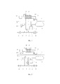
на фиг. 1 - электропневматический тормоз грузового вагона;in FIG. 1 - electro-pneumatic brake of a freight car;
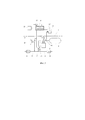
на фиг. 2 - то же самое, с пневмогенератором;in FIG. 2 - the same with a pneumatic generator;
на фиг. 3 - то же самое, с отсечным клапаном.in FIG. 3 - the same with a shut-off valve.
Электропневматический тормоз грузового вагона (фиг. 1) включает в себя тормозную магистраль 1, воздухораспределитель 2 и электромагнитный клапан 3 с датчиком давления 3.1, сообщенные трубопроводами с тормозной магистралью 1. Воздухораспределитель 2 сообщен трубопроводом с запасным резервуаром 4. С подводящим трубопроводом 5 сообщены тормозные цилиндры 6 и электромагнитный клапан 7 с датчиком давления 7.1. Управление электромагнитными клапанами 3 и 7 осуществляется посредством электрической связи, осуществляемой путем передачи управляющего сигнала от контроллера 8. С контроллером 8 электрически связан также электромагнитный вентиль 9. Передача управляющего сигнала от контроллера 8 на электромагнитные клапаны 3, 7 и электромагнитный вентиль 9 и обратная связь в виде контрольного сигнала на контроллер 8 от датчиков давления 3.1 и 7.1 осуществляется посредством проводов, либо беспроводных средств передачи данных. Электромагнитный вентиль 9 трубопроводом сообщен с устройством, автоматически изменяющим давление в тормозном цилиндре 6 в зависимости от загрузки вагона (устройство авторежима 10). Устройство авторежима 10 через обратный клапан 11 сообщено с подводящим трубопроводом 5.The electro-pneumatic brake of a freight car (Fig. 1) includes a
Контроллер 8, электромагнитные клапаны 3, 7 с датчиками давления 3.1, 7.1 и электромагнитный вентиль 9 составляют в совокупности электрическую часть предлагаемого электропневматического тормоза.The
Для питания контроллера 8 на грузовом вагоне установлен генератор переменного тока 12. Дополнительно в системе питания контроллера 8 предусмотрен резервный аккумулятор 13. Контроллер 8 снабжен датчиками телеметрии, датчиками сбора и обмена информацией с другими грузовыми вагонами, а также датчиками определения местонахождения единицы железнодорожного транспортного средства.To power the
Возможен вариант исполнения электропневматического тормоза грузового вагона, в котором в качестве генератора переменного тока применяется генератор с пневматическим приводом, преобразующий энергию сжатого воздуха из тормозной магистрали в электрический ток (фиг. 2). В такой схеме электропневматического тормоза пневматический генератор 12 сообщен с тормозной магистралью 1 трубопроводом, на котором установлен электромагнитный клапан 12.1. Управление электромагнитным клапаном 12.1 осуществляется посредством электрической связи, осуществляемой путем передачи управляющего сигнала от контроллера 8.An electro-pneumatic brake of a freight car is possible, in which a generator with a pneumatic drive is used as an alternating current generator, which converts the energy of compressed air from the brake line into electric current (Fig. 2). In such an electro-pneumatic brake circuit, the
Возможен также вариант исполнения электропневматического тормоза грузового вагона (фиг. 3), в котором на трубопроводе, сообщающем воздухораспределитель 2 и тормозную магистраль 1, установлен отсечной клапан 14. Управление отсечным клапаном 14 осуществляется посредством электрической связи, осуществляемой путем передачи управляющего сигнала от контроллера 8. При этом электромагнитный клапан 3 сообщен с трубопроводом, сообщающим воздухораспределитель 2 и тормозную магистраль в той его части, которая расположена между воздухораспределителем 2 и отсечным клапаном 14. Данная схема дает возможность отключения системы грузового вагона от общей для всего грузового состава тормозной магистрали 1 посредством управляющего сигнала от машиниста, например, при аварийных ситуациях для экстренного торможения.A variant of the electro-pneumatic brake of a freight car is also possible (Fig. 3), in which a shut-off
Полезная модель работает следующим образом.The utility model works as follows.
При торможении управляющий сигнал по каналам связи из кабины машиниста приходит на контроллер 8. Управляющий сигнал от контроллера 8 по соответствующим каналам электрической связи поступает одновременно на электромагнитные клапаны 3, 7 и на электромагнитный вентиль 9. Электромагнитный клапан 3, сообщенный с тормозной магистралью 1, начинает сбрасывать давление в тормозной магистрали 1, приводя в действие воздухораспределитель 2, который начинает подавать воздух из запасного резервуара 4 к электромагнитному клапану 7, сообщенному трубопроводом с подводящим трубопроводом 5. Электромагнитный клапан 7 воспринимает управляющий сигнал от контроллера 8, который открывает электромагнитный клапан 7 на величину, соответствующую необходимому давлению в тормозных цилиндрах 6, в результате чего в тормозные цилиндры 6 подается воздух с заданным давлением.When braking, the control signal through the communication channels from the driver’s cab arrives at
В режиме отпуска тормозов значение давления в тормозной магистрали 1 повышается от управляющего воздействия со стороны крана машиниста, подающего сжатый воздух в тормозную магистраль 1. Контрольный сигнал от датчика давления 3.1, сообщенного с тормозной магистралью 1, поступает в контроллер 8. Из контроллера 8 на электромагнитный клапан 7 поступает управляющий сигнал. Электромагнитный клапан 7 начинает сбрасывать давление из тормозных цилиндров 6 в атмосферу. При этом воздухораспределитель 2 обеспечивает зарядку сжатым воздухом запасного резервуара 4.In the brake release mode, the pressure in the
Контроль корректности управляющего сигнала осуществляется контроллером 8 путем обработки обратных, контрольных сигналов от датчиков давления 3.1 и 7.1.The control signal is checked by the
При управлении электропневматическим тормозом в режиме работы электрической части также работают электромагнитный вентиль 9 и обратный клапан 11. Электромагнитный вентиль 9 перекрывает поток воздуха к устройству авторежима 10. Обратный клапан 11 не позволяет сжатому воздуху, подаваемому к тормозным цилиндрам 6, уходить на авторежим 10.When controlling the electro-pneumatic brake in the operation mode of the electrical part, the
В случае отказа в работе электрической части электропневматического тормоза срабатывает устройство авторежима 10, и в работу включается пневматическая часть электропневматического тормоза, работающая по известным принципам.In the event of a failure in the electrical part of the electro-pneumatic brake, the auto-
Claims (5)
Priority Applications (1)
| Application Number | Priority Date | Filing Date | Title |
|---|---|---|---|
| RU2019120939U RU196698U1 (en) | 2019-07-02 | 2019-07-02 | ELECTRIC PNEUMATIC BRAKE OF THE FREIGHT WAGON |
Applications Claiming Priority (1)
| Application Number | Priority Date | Filing Date | Title |
|---|---|---|---|
| RU2019120939U RU196698U1 (en) | 2019-07-02 | 2019-07-02 | ELECTRIC PNEUMATIC BRAKE OF THE FREIGHT WAGON |
Publications (1)
| Publication Number | Publication Date |
|---|---|
| RU196698U1 true RU196698U1 (en) | 2020-03-12 |
Family
ID=69897941
Family Applications (1)
| Application Number | Title | Priority Date | Filing Date |
|---|---|---|---|
| RU2019120939U RU196698U1 (en) | 2019-07-02 | 2019-07-02 | ELECTRIC PNEUMATIC BRAKE OF THE FREIGHT WAGON |
Country Status (1)
| Country | Link |
|---|---|
| RU (1) | RU196698U1 (en) |
Cited By (1)
| Publication number | Priority date | Publication date | Assignee | Title |
|---|---|---|---|---|
| RU2779332C1 (en) * | 2022-03-03 | 2022-09-06 | Общество с ограниченной ответственностью "Всесоюзный научно-исследовательский центр транспортных технологий" (ООО "ВНИЦТТ") | Electric-pneumatic brake for cargo car (options) |
Citations (3)
| Publication number | Priority date | Publication date | Assignee | Title |
|---|---|---|---|---|
| RU2384437C1 (en) * | 2008-06-09 | 2010-03-20 | Открытое акционерное общество "Транспневматика" | Railroad vehicle electropneumatic brake |
| RU2600470C1 (en) * | 2015-06-19 | 2016-10-20 | Акционерное Общество "Научно-Производственный Центр "Промэлектроника" | Railway vehicle braking control system |
| RU2608191C2 (en) * | 2015-01-12 | 2017-01-17 | Общество с ограниченной ответственностью Научно-производственное объединение "РаТорм" (ООО НПО "РаТорм") | Method of electropneumatic control over air distributor and device for its implementation (versions) |
-
2019
- 2019-07-02 RU RU2019120939U patent/RU196698U1/en active
Patent Citations (3)
| Publication number | Priority date | Publication date | Assignee | Title |
|---|---|---|---|---|
| RU2384437C1 (en) * | 2008-06-09 | 2010-03-20 | Открытое акционерное общество "Транспневматика" | Railroad vehicle electropneumatic brake |
| RU2608191C2 (en) * | 2015-01-12 | 2017-01-17 | Общество с ограниченной ответственностью Научно-производственное объединение "РаТорм" (ООО НПО "РаТорм") | Method of electropneumatic control over air distributor and device for its implementation (versions) |
| RU2600470C1 (en) * | 2015-06-19 | 2016-10-20 | Акционерное Общество "Научно-Производственный Центр "Промэлектроника" | Railway vehicle braking control system |
Cited By (1)
| Publication number | Priority date | Publication date | Assignee | Title |
|---|---|---|---|---|
| RU2779332C1 (en) * | 2022-03-03 | 2022-09-06 | Общество с ограниченной ответственностью "Всесоюзный научно-исследовательский центр транспортных технологий" (ООО "ВНИЦТТ") | Electric-pneumatic brake for cargo car (options) |
Similar Documents
| Publication | Publication Date | Title |
|---|---|---|
| US11180128B2 (en) | System and method for controlling centralized brake of vehicles, a motor train set brake control system | |
| CN101600611B (en) | Parking brake module for a pressure medium-operated brake system | |
| CN100413739C (en) | Braking systems for vehicles, in particular utility vehicles, comprising at least two separate electronic braking control circuits | |
| CN101495350B (en) | For the brake equipment of automobile | |
| US5934764A (en) | Method for limiting brake cylinder pressure on locomotives equipped with distributive power and electronic brake systems | |
| US9022488B2 (en) | Fault-tolerant vehicle brake system | |
| US6839664B1 (en) | Electrically controlled pneumatic end of train pneumatic emulation system | |
| TWI312324B (en) | Pneumatic emergency brake assurance module | |
| US6189980B1 (en) | Locomotive to ECP brake conversion system | |
| CN101939199A (en) | Parking brake for a vehicle and method for operating the parking brake | |
| MXPA05006155A (en) | Interface system from pneumatic to electrically-controlled pneumatic brake systems. | |
| CN114728643B (en) | Brake system for a motor vehicle and trailer air supply and control module | |
| CN106660536A (en) | Pneumatic device for a vehicle, comprising an integrated pressurized emergency reservoir | |
| CA2568461C (en) | Brake pipe control system with remote radio car | |
| RU196698U1 (en) | ELECTRIC PNEUMATIC BRAKE OF THE FREIGHT WAGON | |
| CN112026734A (en) | Air brake isolation device of railway vehicle and control circuit of emergency brake interlocking | |
| CN102189986B (en) | High-reliability rail transit vehicle brake system | |
| RU198428U1 (en) | BRAKE EQUIPMENT UNIT | |
| RU2524751C1 (en) | Truck brake adaptive control unit | |
| RU46983U1 (en) | EXECUTIVE PART OF Pneumatic BRAKE SYSTEM OF PASSENGER LOCOMOTIVE | |
| CN212473427U (en) | Air brake isolation device of railway vehicle and control circuit of emergency brake interlocking | |
| US6050650A (en) | Application solenoid valve for electronically controlled freight train brake system | |
| CA2244638C (en) | 26-type electronic controlled pneumatic conversion block | |
| CN111071228A (en) | Electric control air pressure braking system of intelligent rail electric car | |
| RU210447U1 (en) | Parking brake unit |