RU17543U1 - SURFACE LENGTH ELASTIC ELEMENT - Google Patents
SURFACE LENGTH ELASTIC ELEMENT Download PDFInfo
- Publication number
- RU17543U1 RU17543U1 RU2000119532/20U RU2000119532U RU17543U1 RU 17543 U1 RU17543 U1 RU 17543U1 RU 2000119532/20 U RU2000119532/20 U RU 2000119532/20U RU 2000119532 U RU2000119532 U RU 2000119532U RU 17543 U1 RU17543 U1 RU 17543U1
- Authority
- RU
- Russia
- Prior art keywords
- rail
- section
- vertical section
- element according
- height
- Prior art date
Links
- 239000010426 asphalt Substances 0.000 description 1
- 238000010276 construction Methods 0.000 description 1
- 238000013016 damping Methods 0.000 description 1
- 239000013013 elastic material Substances 0.000 description 1
- 238000004519 manufacturing process Methods 0.000 description 1
- 239000000463 material Substances 0.000 description 1
- 230000000717 retained effect Effects 0.000 description 1
Landscapes
- Railway Tracks (AREA)
Abstract
1. Прирельсовый длинномерный упругий элемент, содержащий сквозной канал и продольные гофры, отличающийся тем, что элемент в поперечном сечении выполнен в виде фигуры, образованной вертикальным участком, противоположным ему участком, выполненным в виде кривой второго порядка, например, окружности, и двумя соединяющими их верхним и нижним участками, причем верхний участок преимущественно ориентирован горизонтально, нижний - параллельно верхней поверхности подошвы рельса, а сквозной канал образован внутренними стенками упомянутых участков.2. Элемент по п.1, отличающийся тем, что его ширина составляет 62-68 мм, а высота вертикального участка - 109-115 мм.3. Элемент по пп.1 и 2, отличающийся тем, что высота его вертикального участка составляет 127-133 мм.4. Элемент по п.1, отличающийся тем, что его ширина составляет 57-63 мм, а высота вертикального участка - 117-123 мм.5. Элемент по пп.1-4, отличающийся тем, что толщина его боковых стенок составляет 10-14 мм.1. Rail long elastic element containing a through channel and longitudinal corrugations, characterized in that the element in cross section is made in the form of a figure formed by a vertical section opposite to it, made in the form of a second-order curve, for example, a circle, and two connecting them upper and lower sections, the upper section being mainly oriented horizontally, the lower section parallel to the upper surface of the rail sole, and the through channel is formed by the inner walls of the sections B.2. The element according to claim 1, characterized in that its width is 62-68 mm, and the height of the vertical section is 109-115 mm. An element according to claims 1 and 2, characterized in that the height of its vertical section is 127-133 mm. 4. The element according to claim 1, characterized in that its width is 57-63 mm, and the height of the vertical section is 117-123 mm. An element according to claims 1 to 4, characterized in that the thickness of its side walls is 10-14 mm.
Description
Полезная модель относиться к элементам конструкции верхнего строения путей для рельсовых транспортных средств и преимущественна может быть использована для устройства трамвайных и железнодорожных путей, совмещенных с проезжей частью дороги.The utility model refers to the structural elements of the upper structure of tracks for rail vehicles and can be used primarily for the construction of tram and railway tracks combined with the carriageway.
Известна рельсовая конструкция для трамвайных путей, включающая прирельсовые элементы из упругого материала, содержащие сквозные каналы и гофры (DE 29517001 U1 07.02.27. (9714) ЕО1В21/02).Known rail design for tram tracks, including rail elements of elastic material containing through channels and corrugations (DE 29517001 U1 07.02.27. (9714) EO1B21 / 02).
Известный прирельсовый элемент характеризуется сравнительно большой материальностью в связи с тем, что его верхний участок совмещен с верхней частью головки рельса, а сквозные каналы образованы неоправданно толстыми стенами.The well-known rail element is characterized by relatively great materiality due to the fact that its upper section is combined with the upper part of the rail head, and the through channels are formed by unjustifiably thick walls.
Задача, на решение которой направлена заявленная полезная модель, состоит в снижении материалоемкости прирельсового элемента, повышение технологичности его изготовления, а, следовательно, снижения его стоимости. При этом сохраняются основные технические характеристики элемента, обусловленные его демпфирующими и шумопоглощающими свойствами.The problem to which the claimed utility model is directed is to reduce the material consumption of the rail element, increase the manufacturability of its manufacture, and, therefore, reduce its cost. At the same time, the basic technical characteristics of the element, due to its damping and sound-absorbing properties, are retained.
Эта задача решается за счет того, что прирельсовый элемент в поперечном сечении выполнены в виде фигуры, образованной вертикальным участком, противоположным ему участком, образованным кривой второго порядка, например окружностью и двумя соединяющими их верхним и нижним участками, причем верхний участок преимущественно ориентирован горизонтально, нижний - параллельно верхней поверхности подошвы рельса, а сквозной канал образован внутренними стенками упомянутых участков.This problem is solved due to the fact that the rail element in cross section is made in the form of a figure formed by a vertical section, an opposite section formed by a second-order curve, for example, a circle and two upper and lower sections connecting them, the upper section being predominantly oriented horizontally, the lower - parallel to the upper surface of the rail sole, and the through channel is formed by the inner walls of said sections.
При этом в зависимости от типа рельсов используемых для устройства пути ширина и высота элемента различны.Moreover, depending on the type of rails used for the device paths, the width and height of the element are different.
Для стандартного желобчатого (трамвайного) рельса типа Т-62 ширина элемента находится в пределах 62-68 мм, высота его вертикального участка со стороны желоба рельса - 109-115 мм, а с противоположной стороны рельса высота вертикального участка 127-133 мм.For a standard grooved (tram) rail of the T-62 type, the width of the element is in the range of 62-68 mm, the height of its vertical section from the side of the rail groove is 109-115 mm, and the height of the vertical section from the opposite side of the rail is 127-133 mm.
Для стандартного железнодорожного рельса типа Р-65 ширина элемента находится в пределах 57-63 мм, а высота его вертикального участка - 117-123 мм. При этом толщина боковых стенок элемента составляет 10-14 мм.For a standard P-65 rail, the width of the element is between 57-63 mm and the height of its vertical section is 117-123 mm. The thickness of the side walls of the element is 10-14 mm.
Полезная модель поясняется чертежами.The utility model is illustrated by drawings.
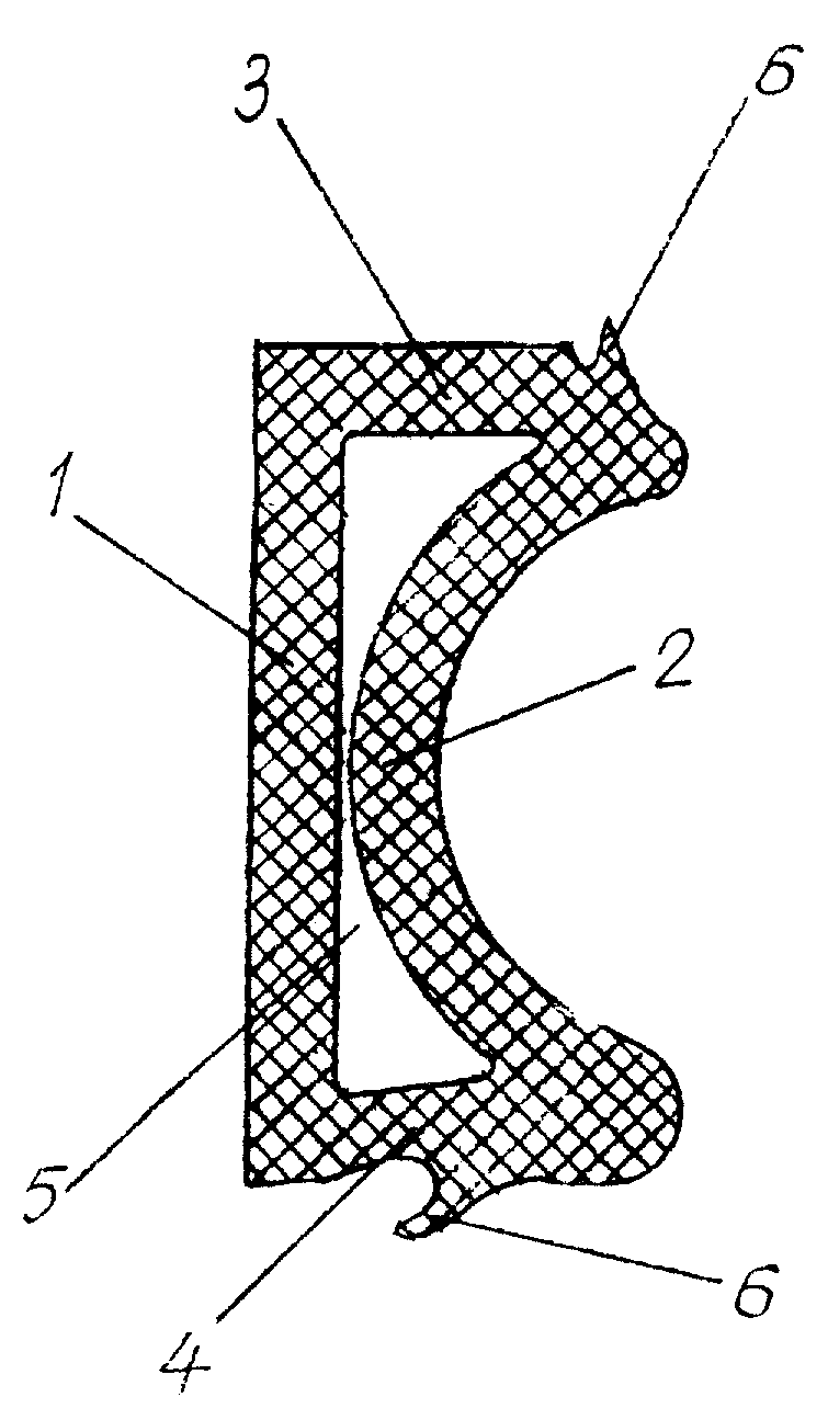
На фиг. 1 изображено поперечное сечение прирельсового длинномерного упругого элемента.In FIG. 1 shows a cross section of a rail long elastic member.
На фиг. 2 - поперечное сечение конструкции рельсового пути с использование желобчатого рельса.In FIG. 2 is a cross-sectional view of a rail structure using a grooved rail.
На фиг. 3 - поперечное сечение конструкции рельсового пути с использованием стандартного железнодорожного рельса.In FIG. 3 is a cross-sectional view of a rail structure using a standard rail.
Заявленный прирельсовый длинномерный упругий элемент (фиг. 1) состоит из вертикального участка 1, противоположного ему участка 2, образованного кривой второго порядка, например, окружностью и соединяющих их верхним 3 и нижним 4 участками. Все упомянутые участки выполнены заодно, из резины и их внутренние стенки образуют сквозной канал 5.The claimed rail long elastic element (Fig. 1) consists of a vertical section 1, the opposite section 2, formed by a second-order curve, for example, a circle and connecting their upper 3 and lower 4 sections. All these sections are made at the same time, of rubber and their inner walls form a through channel 5.
Верхний 3 и нижний 4 участки элемента содержат выполненные заодно с ними гофры 6.The upper 3 and lower 4 sections of the element contain made at the same time corrugations 6.
Характеризующая заявляемое устройство совокупность существенных признаков не известна из уровня техники, следовательно, полезная модель отвечает условию «новизна.The set of essential features characterizing the claimed device is not known from the prior art, therefore, the utility model meets the condition of “novelty.
На предприятии заявителе изготовлены из резины и испытаны опытные образцы прирельсовых длинномерных (до 25 м) элементов, что подтверждает соответствие полезной модели условию «промышленная применимость.The applicant company made rubber and tested prototypes of long rail (up to 25 m) elements, which confirms the compliance of the utility model with the condition “industrial applicability.
На фиг. 2 показано расположение прирельсовых упругих элементов на желобчатом рельсе 7, установленном на подрельсовой резиновой подкладке 8.In FIG. 2 shows the location of the rail elastic elements on the grooved rail 7 mounted on the rail rubber lining 8.
На фиг. 3 изображено расположение прирельсовых упругих элементов на стандартном железнодорожном рельсе 9, установленном на подрельсовой резиновой подкладке 8.In FIG. 3 shows the arrangement of rail elastic elements on a standard rail 9 mounted on a rail rubber lining 8.
Прирельсовые длинномерные упругие элементы с внешних относительно рельса сторон фиксируют бетонными конструкциями и литым асфальтом.Long-length rail elastic elements are fixed from the sides external to the rail with concrete structures and cast asphalt.
Claims (5)
Priority Applications (1)
| Application Number | Priority Date | Filing Date | Title |
|---|---|---|---|
| RU2000119532/20U RU17543U1 (en) | 2000-07-21 | 2000-07-21 | SURFACE LENGTH ELASTIC ELEMENT |
Applications Claiming Priority (1)
| Application Number | Priority Date | Filing Date | Title |
|---|---|---|---|
| RU2000119532/20U RU17543U1 (en) | 2000-07-21 | 2000-07-21 | SURFACE LENGTH ELASTIC ELEMENT |
Publications (1)
| Publication Number | Publication Date |
|---|---|
| RU17543U1 true RU17543U1 (en) | 2001-04-10 |
Family
ID=48277614
Family Applications (1)
| Application Number | Title | Priority Date | Filing Date |
|---|---|---|---|
| RU2000119532/20U RU17543U1 (en) | 2000-07-21 | 2000-07-21 | SURFACE LENGTH ELASTIC ELEMENT |
Country Status (1)
| Country | Link |
|---|---|
| RU (1) | RU17543U1 (en) |
Cited By (1)
| Publication number | Priority date | Publication date | Assignee | Title |
|---|---|---|---|---|
| RU187947U1 (en) * | 2018-05-03 | 2019-03-25 | Общество с ограниченной ответственностью "Научно-производственное предприятие "Транс Инвест" | Elastic vibration damper profile for rails |
-
2000
- 2000-07-21 RU RU2000119532/20U patent/RU17543U1/en active
Cited By (1)
| Publication number | Priority date | Publication date | Assignee | Title |
|---|---|---|---|---|
| RU187947U1 (en) * | 2018-05-03 | 2019-03-25 | Общество с ограниченной ответственностью "Научно-производственное предприятие "Транс Инвест" | Elastic vibration damper profile for rails |
Similar Documents
| Publication | Publication Date | Title |
|---|---|---|
| WO1997045592A1 (en) | Track soundproofing arrangement | |
| RU2006146012A (en) | OVERLAPPING DEVICE | |
| EP2623670A3 (en) | Ballastless railway track structure for rail vehicles | |
| CN103485246A (en) | Rubber vibration isolation pad | |
| RU17543U1 (en) | SURFACE LENGTH ELASTIC ELEMENT | |
| DK1130162T3 (en) | Concrete-free sleepers | |
| KR101333527B1 (en) | Beam bridge that use corrugated steelplate | |
| IL160098A0 (en) | Rigid track | |
| JP2006214269A5 (en) | ||
| CN210031351U (en) | Prefabricated formula floating plate way bed vibration isolation system | |
| RU109465U1 (en) | REINFORCED concrete sleepers | |
| SU923376A3 (en) | Rail track with prefabricated foundation | |
| RU2716068C1 (en) | Railway crossing | |
| DE3134473A1 (en) | Ballastless superstructure for railways | |
| ITMI20012404A1 (en) | UNDERBALLAST DAMPING DEVICE PARTICULARLY DESIGNED FOR RAILWAY LINES | |
| DE3737567A1 (en) | Noise protection arrangement for railway lines | |
| CN205636377U (en) | Railway roadbed abatvoix | |
| CN106702829B (en) | Open type elastic short rail sleeper vibration damping track | |
| ATE506492T1 (en) | ENDLESS GABION WALL | |
| CN206385393U (en) | Non-fragment orbit | |
| RU230305U1 (en) | RAIL FOOT PROFILE FOR GROOVED RAIL | |
| RU167457U1 (en) | REINFORCED CONCRETE BEDROOM FOR TRAMWAYS WITH THREE HORIZONTAL SITES FOR INSTALLING ROADS | |
| RU2009116672A (en) | MULTI-RAIL RAILWAY AND TRAIN WITH CROSS MOVEMENT MECHANISM | |
| RU2785146C1 (en) | Dampening sleep pad | |
| DE661279C (en) | Insulated wooden sleeper bedding |