KR950002027B1 - Switch for escalator - Google Patents
Switch for escalator Download PDFInfo
- Publication number
- KR950002027B1 KR950002027B1 KR1019860009253A KR860009253A KR950002027B1 KR 950002027 B1 KR950002027 B1 KR 950002027B1 KR 1019860009253 A KR1019860009253 A KR 1019860009253A KR 860009253 A KR860009253 A KR 860009253A KR 950002027 B1 KR950002027 B1 KR 950002027B1
- Authority
- KR
- South Korea
- Prior art keywords
- escalator
- switch
- air bag
- skirt panel
- panel
- Prior art date
Links
Images


Classifications
-
- H—ELECTRICITY
- H01—ELECTRIC ELEMENTS
- H01H—ELECTRIC SWITCHES; RELAYS; SELECTORS; EMERGENCY PROTECTIVE DEVICES
- H01H3/00—Mechanisms for operating contacts
- H01H3/02—Operating parts, i.e. for operating driving mechanism by a mechanical force external to the switch
- H01H3/16—Operating parts, i.e. for operating driving mechanism by a mechanical force external to the switch adapted for actuation at a limit or other predetermined position in the path of a body, the relative movement of switch and body being primarily for a purpose other than the actuation of the switch, e.g. for a door switch, a limit switch, a floor-levelling switch of a lift
-
- B—PERFORMING OPERATIONS; TRANSPORTING
- B66—HOISTING; LIFTING; HAULING
- B66B—ELEVATORS; ESCALATORS OR MOVING WALKWAYS
- B66B29/00—Safety devices of escalators or moving walkways
- B66B29/02—Safety devices of escalators or moving walkways responsive to, or preventing, jamming by foreign objects
Abstract
내용없음.None.
Description
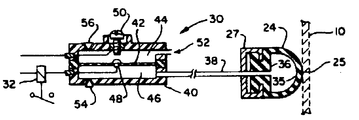
제1도는 본 발명에 따른 에스컬레이터용 스위치의 부분 단면 파단 사시도.1 is a partial cross-sectional cutaway perspective view of a switch for an escalator according to the present invention.
제2도는 비작동 상태에 있는 스위치 기구의 단면도.2 is a sectional view of a switch mechanism in an inoperative state.
제3도는 작동 상태에 있는 스위치 기구의 단면도.3 is a sectional view of a switch mechanism in an operating state.
* 도면의 주요부분에 대한 부호의 설명* Explanation of symbols for main parts of the drawings
10 : 스커트 판넬 12 : 에스컬레이터 계단10
14 : 트러스 부재 24 : 공기 주머니14: truss member 24: air bag
26 : 계단 디딤판(tread) 27 : 레일26: stair tread 27: rail
28, 29 : 보강 부재 25 : 공기 주머니 접촉지역28, 29: reinforcing member 25: air bag contact area
30 : 압력 스위치 32 : 차단 릴레이30: pressure switch 32: disconnect relay
33 : 모터 34 : 에스컬레이터 브레이크33: motor 34: escalator brake
40 : 하우징 42 : 다이어프램40
44 : 대기압 체임버 46 : 공기 주머니 압력 체임버44: atmospheric pressure chamber 46: air bag pressure chamber
48, 50 : 전기 접점48, 50: electrical contacts
본 발명은 에스컬레이터의 안전 장치에 관한 것이다.The present invention relates to a safety device of an escalator.
종래, 에스컬레이터의 인접 부품들 사이의 유동 간격으로 인하여 물체가 걸릴 위험이 있었다. 국립 표준치(규칙)에 표시된대로 그러한 간격들을 궁극적으로 실용적인 수준으로 감소시키는 것이 외관상 한가지 해결 방법이 될 수 있다. 난간 스커트 판넬에서 계단 간격까지의 지역은, 난간 스커트의 마찰을 작게 하도록 특수한 물질로 만들어지거나 표면 코팅을 해왔다. 그러나, 계단과 스커트 판넬 사이에 물체가 걸릴 가능성이 여전히 존재한다. 이로 인하여 스커트 판넬이 안쪽으로 휘어진다. 스커트 판넬이 휘어지는 경우에 에스컬레이터를 일시적으로 정지시키기 위해서, 종래에는 계단이 반대쪽에 스커트 판넬의 길이를 따라 스커트 판넬 뒷쪽의 불연속적인 위치들에 마이크로 스위치들을 설치해 두었다. 이 마이크로 스위치가 작동되면 에스컬레이터 구동모터가 정지되어 제동력이 가해지는 것이다. 이와 같이 마이크로 스위치를 불연속적인 간격으로 배치해두면, 스커트 판넬의 전체 길이를 따라 연속적인 휨 감지 센서의 역할을 실행할 수 없으므로 "완전한" 안전 보장이 이루어지지 못한다.Conventionally, there was a risk of object jamming due to the flow gap between adjacent parts of the escalator. As indicated by the National Standards (Rules), reducing such gaps to a practical level ultimately may be one solution in appearance. Areas from handrail skirt panels to stairway spacing have been made of special materials or surface coatings to reduce the friction of handrail skirts. However, there is still the possibility of objects being caught between the stairs and the skirting panel. This causes the skirting panel to bend inward. In order to temporarily stop the escalator when the skirt panel is bent, the microswitches were conventionally installed in discrete positions behind the skirt panel along the length of the skirt panel on the opposite side. When this micro switch is activated, the escalator drive motor is stopped to apply braking force. If the microswitches are arranged at discontinuous intervals in this way, they cannot play the role of a continuous bending sensor along the entire length of the skirting panel and thus cannot provide a “complete” safety guarantee.
전술한 바와 같은 문제점을 감안하여 이루어진 본 발명은, 스커트 판넬과 계단 사이에 물체가 걸리는 상황이 발생할 경우에 에스컬레이터를 일시 정지시키도록 완전한 범위에 걸쳐 안전을 보장할 수 있는 에스컬레이터용 스위치를 제공하는 것을 그 목적으로 하고 있다.SUMMARY OF THE INVENTION The present invention has been made in view of the above-described problems, and it is an object of the present invention to provide a switch for an escalator that can guarantee safety over a full range so as to pause the escalator when an object is caught between the skirt panel and the stairs. It is for that purpose.
본 발명에 따르면, 기다란 관 모양의 공기 주머니가 계단 반대쪽에서 에스컬레이터 스커트 판넬의 안쪽과 접촉된채 배치되어 있다. 어떤 물체가 계단과 스커트 판넬 사이의 유동 간격에 걸리어 스커트 판넬이 안쪽으로 휘어질 때 공기 주머니 내의 공기 압력이 증가한다. 이때, 공기 주머니내의 공기 압력 증가에 감응하여 압력 작용식 전기 스위치가 릴레이를 제어하여, 결과적으로 에스컬레이터를 일시 정지시킨다.According to the invention, an elongated tubular air pocket is arranged in contact with the inside of the escalator skirt panel opposite the stairs. When an object is caught in the flow gap between the stairs and the skirt panel, the air pressure in the air bag increases as the skirt panel flexes inward. At this time, in response to an increase in the air pressure in the air bag, the pressure-operated electric switch controls the relay, resulting in a pause of the escalator.
이하, 첨부된 도면을 참조하여 본 발명의 실시예에 대하여 더욱 상세히 설명하면 다음과 같다.Hereinafter, exemplary embodiments of the present invention will be described in detail with reference to the accompanying drawings.
제1도에는 난간 스커트 판넬(10), 그 판넬의 바깥쪽에 놓인 에스컬레이터 계단(12), 및 여러가지 에스컬레이터 부품들을 지지하도록 판넬 안쪽(즉, 뒷쪽)에 놓인 트러스 부재(14)가 도시된다. 판넬(10)은 그의 윗쪽 가장자리(16)와 그의 아랫쪽 가장자리(18) 근처가 버팀대(brace), 바닥 부분등과 같은 에스컬레이터 고정 부품들(20, 22)에 부착되어 있다.FIG. 1 shows a
기다란 관 모양의 공기 주머니(24)가 판넬(10) 뒤에 배치되어 계단 디딤판(26) 반대쪽에서 공기 주머니 접촉 지역(25)과 접촉하여 있고, 스커트 판넬의 길이를 따라 길이방향으로 연장된다. 공기 주머니는 그의 양끝이 적당한 밀봉수단(도시안됨)에 의해 폐쇄되어 있고, 보강 레일(27)에 의해 트러스 부재(14)에 장착되어 있다. 당 분야에서 통상의 지식을 가진자라면, 본 발명은 계단이 없고, 연속적인 벨트로 구성된 움직이는 보도(travolator)에 대해서도 똑같이 적용될 수 있음을 알 수 있을 것이다.An elongated
스커트 판넬은 공기 주머니 접촉 지역(25)의 상하로 판넬 안쪽에 위치한 길이방향 보강 부재들(28, 29)에 의해 보강되어 있다. 이로써 공기 주머니 접촉 지역(25)의 스커트 판넬(10) 중에서 가장 휘기쉬운 지역이되므로 계단과 스커트 판넬 사이에 물체가 걸리면 즉시 판넬이 안쪽으로 휘게 될 것이다. 판넬이 안쪽으로 휘어지면 공기 주머니가 가압된다. 공기 주머니(24)내의 공기 흐름과 소통되는 압력 작용식 스위치(30)는 상기한 가압된 압력에 감응하여 적절한 차단 릴레이(32)를 동작시켜서 에스컬레이터 모우터(33)를 정지시키고 에스컬레이터 브레이크(34)를 작동시킨다.The skirt panel is reinforced by longitudinal reinforcing
제2도에서는 공기 주머니(24)와 압력 스위치(30)를 더 상세하게 나타낸다. 공기 주머니(24)는 무부하 상태에서는 변형되지 않은채 스커트 판넬(10)과 맞닿아진다. 공기 주머니의 횡단면은 반원형이고, 반원의 꼭대기(35)는 판넬(10)과 맞닿아 있고, 반원의 기부(36)는 레일(27)에 의해 보유되어 있다. 공기 주머니의 꼭대기 부분은 쉽게 변형될 수 있도록 비교적 얇은 벽으로 되어 있다. 공기 주머니의 기부 부분은 꼭대기 부분보다 더 두껍게 되어 있고 그의 위 아랫면을 따라 길이방향으로 홈이 파여져 있어서 "C"자형 단면의 레일(27)안으로 확실하게 스냅 끼워 맞춤되어 있다. PVC 튜브(38)와 같은 통로가 공기 주머니(24)와 스위치(30) 사이에 공기 흐름이 소통되게 한다.2 shows the
스위치(30)는 다이어프램(42)에 의해 2개의 체임버들, 즉 대기압 체임버(44)와 공기 주머니 압력 체임버(46)로 분할된 하우징(40)을 포함한다. 다이어프램(42)에는 그의 중앙에 대기압 체임버 측으로 배치된 전기 접점(48)이 제공되어 스위치(30)를 적절하게 바깥쪽과 도선으로 접속시키게 된다. 하우징(40)에도 전기 접점(48)에 인접하게 대응하는 나사조정 전기 접점(50)이 대기압 체임버 측으로 배치되어 스위치를 바깥쪽과 적절하게 도선으로 접속시키게 된다. 공기 주머니(24)에 부하가 걸리지 않을 때, 다시말해서 스커트 판넬이 휘어지지 않으면, 접점들(48, 50)은 평상시에 개방되어 있다.The
제3도에 도시된 바와 같이, 스커트 판넬(10)이 변형되면, 공기 주머니(24)에 하중이 걸리어(불룩해져서) 스위치의 공기 주머니 압력 체임버(46)를 가압시킨다. 그러면 다이어프램(42)이 윗쪽으로 휘어지고, 전기 접점들(48, 50)이 릴레이(32)로의 회로를 완성시키게 된다.As shown in FIG. 3, when the
대기압 체임버(44)는 (52)에서 배기되어 진다. 공기 주머니 압력 체임버(46)에는 안전 밸브(54)가 설치되어 그 체임버내에 파괴적인 레벨의 과압이 형성되지 않게 보호한다. 마찬가지로, 대기압 체임버(44)내의 안전 밸브(56)도 그 체임버내에 파괴적인 레벨의 압력 형성을 방지한다.Atmospheric pressure chamber 44 is exhausted at 52. The
제2도 및 3도에 도시된 바와 같은 공기 주머니/스위치는 스위치 베렝겐-샤프하우젠의 비르허 AG, 스파르테 아파라테바우(Bircher AG, Sparte Apparatebau, in Berringen-Schaffhausen Switzerland)에서 구할 수 있다. 또한, 그 공기 주머니/스위치는 자동 오버헤드 도어의 아랫쪽 가장자리에서 도어의 완전 폐쇄를 감지하거나, 또는 도어 아래로 자동 통과하는 물체와 접촉하는 경우 도어를 역방향으로 이동시키도록 통상적으로 사용되고 있다. 공기 주머니 길이는 3 내지 4m 밖에 이용할 수 없는데 에스컬레이터 길이가 더 긴 경우에는 그 에스컬레이터의 각 측면을 따라 스커트 판넬 휨 감지 스위치들이 연속적으로 배치되어 스커트 판넬의 길이를 따라 연속적인 휨 감지 작용을 제공할 수 있다.Air bags / switches as shown in FIGS. 2 and 3 can be obtained from Switch Berengen-Schaeffhausen, Bircher AG, Sparte Apparatebau, in Berringen-Schaffhausen Switzerland. In addition, the airbags / switches are commonly used to detect the complete closure of the door at the bottom edge of the automatic overhead door, or to move the door in reverse when it comes in contact with an object passing under the door. Air bag lengths are only available from 3 to 4 m. For longer escalator lengths, skirt panel bending detection switches can be placed continuously along each side of the escalator to provide continuous bending detection along the length of the skirt panel. have.
Claims (2)
Applications Claiming Priority (2)
| Application Number | Priority Date | Filing Date | Title |
|---|---|---|---|
| US794,811 | 1985-11-04 | ||
| US06/794,811 US4669597A (en) | 1985-11-04 | 1985-11-04 | Escalator skirt panel |
Publications (2)
| Publication Number | Publication Date |
|---|---|
| KR870005425A KR870005425A (en) | 1987-06-08 |
| KR950002027B1 true KR950002027B1 (en) | 1995-03-08 |
Family
ID=25163751
Family Applications (1)
| Application Number | Title | Priority Date | Filing Date |
|---|---|---|---|
| KR1019860009253A KR950002027B1 (en) | 1985-11-04 | 1986-11-03 | Switch for escalator |
Country Status (10)
| Country | Link |
|---|---|
| US (1) | US4669597A (en) |
| JP (1) | JPH0791018B2 (en) |
| KR (1) | KR950002027B1 (en) |
| CN (1) | CN1006159B (en) |
| AU (1) | AU585080B2 (en) |
| CA (1) | CA1269745A (en) |
| CH (1) | CH672632A5 (en) |
| DE (1) | DE3637400C2 (en) |
| FR (1) | FR2589622B1 (en) |
| GB (1) | GB2182301B (en) |
Families Citing this family (11)
| Publication number | Priority date | Publication date | Assignee | Title |
|---|---|---|---|---|
| US5052539A (en) * | 1989-10-24 | 1991-10-01 | Melvin Simon & Associates, Inc. | Circular escalator |
| NL1001785C1 (en) * | 1995-11-30 | 1996-01-24 | Arthur Van Moerkerken | Security system for escalators. |
| US6152279A (en) * | 1998-03-23 | 2000-11-28 | Jason Incorporated | Strip Barrier Brush assembly |
| US6425472B1 (en) | 2000-08-24 | 2002-07-30 | Jason Incorporated | Strip barrier brush assembly |
| US6595344B1 (en) | 2000-08-24 | 2003-07-22 | Jason Incorporated | Strip barrier brush assembly |
| WO2010112952A1 (en) | 2009-04-03 | 2010-10-07 | Otis Elevator Company | Adjustable bracket for step flange cover |
| DE102010061614A1 (en) | 2010-12-29 | 2012-07-05 | Thyssenkrupp Fahrtreppen Gmbh | Escalator or moving walk |
| CN107662873B (en) * | 2016-07-29 | 2021-08-24 | 奥的斯电梯公司 | Sensor assembly, safety system and passenger conveyor |
| CN107324197B (en) * | 2017-07-28 | 2019-04-26 | 苏州江南嘉捷电梯有限公司 | A kind of apron crush protector |
| TW202104060A (en) | 2019-04-12 | 2021-02-01 | 瑞士商伊文修股份有限公司 | Side monitoring device for a passenger transport system |
| KR102246328B1 (en) * | 2020-05-11 | 2021-04-29 | (주)볼츠원 | Bolt with opening part |
Family Cites Families (10)
| Publication number | Priority date | Publication date | Assignee | Title |
|---|---|---|---|---|
| DE1701126U (en) * | 1955-03-24 | 1955-06-23 | Haushahn Maschinenfabrik C | SAFETY DEVICE TO PREVENT THE RISK OF PINCHING WITH ELEVATORS, SLIDING DOORS AND THE LIKE. |
| CH374169A (en) * | 1959-11-09 | 1963-12-31 | Inventio Ag | Device for stopping escalators, people and goods belt conveyors |
| DE6601754U (en) * | 1967-01-31 | 1969-03-27 | Orenstein & Koppel Ag | DEVICE FOR SWITCHING OFF THE DRIVE MOTOR OF ESCALATORS |
| BE758095A (en) * | 1969-11-03 | 1971-04-01 | Goodyear Tire & Rubber | HANDRAIL PROTECTION DEVICE |
| GB1317954A (en) * | 1970-05-26 | 1973-05-23 | Blackburn D M | Remote control of electrical outlets |
| JPS54122591A (en) * | 1978-03-13 | 1979-09-22 | Hitachi Ltd | Safety device for escalator |
| JPS54159988A (en) * | 1978-06-08 | 1979-12-18 | Hitachi Ltd | Man-conveyor monitor |
| US4369344A (en) * | 1979-07-26 | 1983-01-18 | Vapor Corporation | Sensitive door edge Wiegand module switch assembly |
| US4371762A (en) * | 1979-07-26 | 1983-02-01 | Vapor Corporation | Contactless pressure sensitive switch |
| DE2941773C2 (en) * | 1979-10-16 | 1984-03-08 | Thyssen Aufzüge GmbH, 7303 Neuhausen | Boundary pedestals for escalators or moving walks |
-
1985
- 1985-11-04 US US06/794,811 patent/US4669597A/en not_active Expired - Fee Related
-
1986
- 1986-10-14 CA CA000520381A patent/CA1269745A/en not_active Expired - Lifetime
- 1986-10-29 FR FR868615080A patent/FR2589622B1/en not_active Expired - Lifetime
- 1986-10-30 CH CH4311/86A patent/CH672632A5/de not_active IP Right Cessation
- 1986-11-03 AU AU64676/86A patent/AU585080B2/en not_active Ceased
- 1986-11-03 DE DE3637400A patent/DE3637400C2/en not_active Expired - Fee Related
- 1986-11-03 KR KR1019860009253A patent/KR950002027B1/en not_active IP Right Cessation
- 1986-11-03 CN CN86107634.6A patent/CN1006159B/en not_active Expired
- 1986-11-04 JP JP61262611A patent/JPH0791018B2/en not_active Expired - Lifetime
- 1986-11-04 GB GB8626289A patent/GB2182301B/en not_active Expired
Also Published As
| Publication number | Publication date |
|---|---|
| KR870005425A (en) | 1987-06-08 |
| AU585080B2 (en) | 1989-06-08 |
| DE3637400C2 (en) | 1997-10-02 |
| FR2589622A1 (en) | 1987-05-07 |
| AU6467686A (en) | 1987-05-07 |
| GB2182301B (en) | 1989-10-04 |
| JPS62163225A (en) | 1987-07-20 |
| DE3637400A1 (en) | 1987-05-14 |
| GB2182301A (en) | 1987-05-13 |
| CA1269745A (en) | 1990-05-29 |
| CN86107634A (en) | 1987-05-27 |
| JPH0791018B2 (en) | 1995-10-04 |
| CH672632A5 (en) | 1989-12-15 |
| GB8626289D0 (en) | 1986-12-03 |
| CN1006159B (en) | 1989-12-20 |
| US4669597A (en) | 1987-06-02 |
| FR2589622B1 (en) | 1990-10-12 |
Similar Documents
| Publication | Publication Date | Title |
|---|---|---|
| KR950002027B1 (en) | Switch for escalator | |
| EP0803461A2 (en) | Arrangement in an elevator push button | |
| US20030136635A1 (en) | Handrail vertical load detector | |
| EP3341317B1 (en) | Conveyor device | |
| KR101974193B1 (en) | Apparatus for finger Protection at Sliding Door | |
| KR102245816B1 (en) | Protection switch for a elevator | |
| WO2003069104A1 (en) | Pinching-prevention device for automatic doors, in particular for lifts and/or elevators | |
| AU2020272919B2 (en) | Side monitoring device for a passenger transport system | |
| JPH0853281A (en) | Escalator handrail hood | |
| KR100386522B1 (en) | Handrail Safety Device at Handrail Entrance | |
| KR19990038362U (en) | Elevator door jamming device | |
| KR0167948B1 (en) | Variable step of a bus | |
| JPH0891757A (en) | Deck advance preventing device for escalator | |
| KR100547315B1 (en) | Escalator safety device | |
| KR870008773A (en) | Elevator control | |
| JP2002128449A (en) | Inlet device for man conveyor | |
| RU2129890C1 (en) | Load gravity transportation device | |
| KR930017803A (en) | Man Conveyor | |
| KR950004834B1 (en) | Safety railing for opening of walls | |
| JPS6122940Y2 (en) | ||
| JPH0978965A (en) | Safety device in motor-driven shutter | |
| JP2507645B2 (en) | Railing on passenger conveyor | |
| CN114263375A (en) | High-rise building with novel elevator structure | |
| JPH08245148A (en) | Safety device of elevator | |
| JP2005255295A (en) | Skirt guard contact preventing device of passenger conveyor |
Legal Events
| Date | Code | Title | Description |
|---|---|---|---|
| A201 | Request for examination | ||
| E902 | Notification of reason for refusal | ||
| G160 | Decision to publish patent application | ||
| E701 | Decision to grant or registration of patent right | ||
| GRNT | Written decision to grant | ||
| FPAY | Annual fee payment |
Payment date: 19980302 Year of fee payment: 4 |
|
| LAPS | Lapse due to unpaid annual fee |