KR940000609B1 - Tape cartridge - Google Patents
Tape cartridge Download PDFInfo
- Publication number
- KR940000609B1 KR940000609B1 KR1019860000436A KR860000436A KR940000609B1 KR 940000609 B1 KR940000609 B1 KR 940000609B1 KR 1019860000436 A KR1019860000436 A KR 1019860000436A KR 860000436 A KR860000436 A KR 860000436A KR 940000609 B1 KR940000609 B1 KR 940000609B1
- Authority
- KR
- South Korea
- Prior art keywords
- plate
- case
- magnetic shield
- partition wall
- main surface
- Prior art date
Links
- 238000005192 partition Methods 0.000 claims description 30
- 238000003780 insertion Methods 0.000 claims description 16
- 230000037431 insertion Effects 0.000 claims description 16
- 238000005452 bending Methods 0.000 claims 1
- 230000001105 regulatory effect Effects 0.000 description 8
- 230000004888 barrier function Effects 0.000 description 2
- 238000006073 displacement reaction Methods 0.000 description 2
- 238000010079 rubber tapping Methods 0.000 description 2
- 229910000906 Bronze Inorganic materials 0.000 description 1
- 241000283973 Oryctolagus cuniculus Species 0.000 description 1
- OAICVXFJPJFONN-UHFFFAOYSA-N Phosphorus Chemical compound [P] OAICVXFJPJFONN-UHFFFAOYSA-N 0.000 description 1
- 230000005856 abnormality Effects 0.000 description 1
- 239000010974 bronze Substances 0.000 description 1
- KUNSUQLRTQLHQQ-UHFFFAOYSA-N copper tin Chemical compound [Cu].[Sn] KUNSUQLRTQLHQQ-UHFFFAOYSA-N 0.000 description 1
- 238000004049 embossing Methods 0.000 description 1
- 210000004209 hair Anatomy 0.000 description 1
- 238000005304 joining Methods 0.000 description 1
- 238000000034 method Methods 0.000 description 1
- MOFOBJHOKRNACT-UHFFFAOYSA-N nickel silver Chemical compound [Ni].[Ag] MOFOBJHOKRNACT-UHFFFAOYSA-N 0.000 description 1
- 239000010956 nickel silver Substances 0.000 description 1
- 238000003825 pressing Methods 0.000 description 1
- 230000002787 reinforcement Effects 0.000 description 1
- 230000003014 reinforcing effect Effects 0.000 description 1
- 238000000638 solvent extraction Methods 0.000 description 1
- 238000003860 storage Methods 0.000 description 1
- 210000002268 wool Anatomy 0.000 description 1
Images


Classifications
-
- G—PHYSICS
- G11—INFORMATION STORAGE
- G11B—INFORMATION STORAGE BASED ON RELATIVE MOVEMENT BETWEEN RECORD CARRIER AND TRANSDUCER
- G11B23/00—Record carriers not specific to the method of recording or reproducing; Accessories, e.g. containers, specially adapted for co-operation with the recording or reproducing apparatus ; Intermediate mediums; Apparatus or processes specially adapted for their manufacture
- G11B23/02—Containers; Storing means both adapted to cooperate with the recording or reproducing means
- G11B23/04—Magazines; Cassettes for webs or filaments
- G11B23/08—Magazines; Cassettes for webs or filaments for housing webs or filaments having two distinct ends
- G11B23/087—Magazines; Cassettes for webs or filaments for housing webs or filaments having two distinct ends using two different reels or cores
- G11B23/08707—Details
- G11B23/08792—Shielding devices
-
- G—PHYSICS
- G11—INFORMATION STORAGE
- G11B—INFORMATION STORAGE BASED ON RELATIVE MOVEMENT BETWEEN RECORD CARRIER AND TRANSDUCER
- G11B23/00—Record carriers not specific to the method of recording or reproducing; Accessories, e.g. containers, specially adapted for co-operation with the recording or reproducing apparatus ; Intermediate mediums; Apparatus or processes specially adapted for their manufacture
- G11B23/02—Containers; Storing means both adapted to cooperate with the recording or reproducing means
- G11B23/04—Magazines; Cassettes for webs or filaments
- G11B23/08—Magazines; Cassettes for webs or filaments for housing webs or filaments having two distinct ends
- G11B23/087—Magazines; Cassettes for webs or filaments for housing webs or filaments having two distinct ends using two different reels or cores
- G11B23/08707—Details
- G11B23/08757—Guiding means
- G11B23/08771—Pressure pads
Abstract
내용 없음.No content.
Description
제1도는 본 발명의 중요부의 평면도.1 is a plan view of an important part of the present invention.
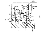
제2도는 제1도에 있어서의 A-A 선의 단면도.2 is a cross-sectional view taken along the line A-A in FIG.
제3도는 제1도에 있어서의 B-B 선의 단면도.3 is a cross-sectional view taken along the line B-B in FIG.
제4도는 본 발명의 아래 케이스의 내면 형상을 도시한 중요부의 사시도.4 is a perspective view of an important part showing the inner surface shape of the lower case of the present invention.
제5도는 본 발명의 위 케이스의 내면 형상을 도시한 중요부의 평면도.5 is a plan view of an important part showing the inner surface shape of the upper case of the present invention.
제6도는 본 발명의 아래 케이스의 내면형상을 도시한 중요부의 평면도.6 is a plan view of an essential part showing the inner shape of the lower case of the present invention.
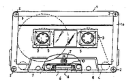
제7도는 본 발명의 대상으로 하는 테이프 카아트리지의 일부를 자른 평면도.7 is a plan view of a part of the tape cartridgeage to be subjected to the present invention.
제8도는 종래예를 설명하는 중요부의 평면도.8 is a plan view of an essential part illustrating a conventional example.
* 도면의 주요부분에 대한 부호의 설명* Explanation of symbols for main parts of the drawings
1 : 본체 케이스 12 : 주면판1: body case 12: main plate
15 : 패드 6 : 헤드 삽입창15: pad 6: head insertion window
13 : 구부림부 16 : 굴곡부13: bend portion 16: bend portion
10 : 자기 차단판 14 : 돌출부10
25 : 사이드 리브25: side rib
본 발명은 제7도에 도시한 것과 같이, 본체케이스(1)의 전면에 마련한 헤드 삽입창(6)의 안쪽 깊숙한 부위에 자기 차단판(10)과 패드 지지용 판스프링(11)을 구비한 테이프 카아트리지에 관한 것이다.As shown in FIG. 7, the
특히, 제1도에 도시한 것과 같이 본체 케이스(1)의 전면에 헤드 삽입창(6)을 갖고, 이 헤드 삽입창(6)의 안쪽 깊숙힌 부위에 평판형태의 주면판(12)의 좌우 양 끝에서 구부림부(13,13)을 앞쪽으로 돌출하여서된 자기차단판(10), 전면의 중앙부위에 패드(15)가 굳게 붙여지고 좌우 양끝에서 굴곡부(16,16)이 뒤쪽으로 돌출하여서된 패드 지지용 판스프링(11)을 구비하고 있으며, 이 판스프링(11)은 상기 구부림부(13)의 앞쪽 끝에서 케이스 안쪽 깊숙한 (뒷쪽)쪽으로의 이동한계가 맞닿아서 규제되어 있음과 동시에, 그 구부림부(13,13)의 각각의 좌우 바깥쪽으로 상기 굴곡부(16,16)이 위치하는 것에 의해, 좌우 가로 방향으로의 엇갈림 움직임이 맞닿아서 규제되어 있는 형태의 테이프 카아트리지에 관한 것이다.In particular, as shown in FIG. 1, the front surface of the main body case 1 has the
이 종류의 테이프 카아트리지에 있어서는, 자기 차단판(10)을 상하, 좌우 및 전후로 덜거덕 거리는 일이 없게 장착하는 것이 요구된다. 이중, 자기 차단판(10)의 상하 방향의 움직임은 본체 케이스(1)을 구성하는 상하 케이스(1a,1b)를 결합한 상태에서 최종적으로 규제된다. 자기 차단판(10)의 좌우 방향으로의 덜거럭 거림도, 예를 들면 자기 차단판(10)의 앞쪽 좌우에 마련한 사이드 리브(25,25)를 구부림부(13,13)의 안쪽 모퉁이 부분에 맞닿게 하는 것에 의해 간단하게 규제된다.In this kind of tape cartridge, it is required to mount the
문제는 자기 차단판(10)의 조립 작업성을 확보한 다음에, 이 전후 방향의 덜거덕 거림을 어떻게 없애는가이다. 패드 지지용 판스트링(11)은 자기 차단판(10)의 양쪽 구부림부(13,13)의 앞쪽 끝에 맞닿는 것에 의해, 케이스 안쪽 깊숙한 쪽으로의 이동한계가 맞닿아서 규제되어 있고, 따라서 자기 차단판(10)이 전후로 덜거럭 거리던지, 위치 정밀도가 나쁘던지 하면, 패드 지지용 판스트링(11)의 지지점위치가 변화하므로, 플레이어의 헤드에 대한 테이프(4)의 패드 누름에 흐트러짐이 일어나, 테이프(4)의 헤드 텃치(head touch)불량이나, 주행 불량을 초래하는 요인으로 되기 때문이다.The problem is how to eliminate the rattling in the front-back direction after securing the workability of assembling the
이 점에 관하여, 종래부터 자기 차단판(10)의 강도를 높이기 위해 주면판(12)의 뒷면쪽에 돌출부(14)를 엠보스(emboss) 가공하는 것이 알려지고 있다. 이 돌출부(14)는 주면판(12)의 중앙의 1개소에 있던지, 도면에 도시한 바와 같이 중앙과 좌우의 각각 상하에 위치시켜서 합계 5개소에 마련하던지 한다. 그리고, 돌출부(14)로 주면판(1)의 외관상의 두께를 확보하고 이 돌출부(14)를 이용해서 자기 차단판(10)을 전후로 덜거덕 거림이 없게 장착하는 것이 실시되고 있다.In this regard, it has been known to emboss the
여기서는, 종래에 일반적으로 제8도에 도시한 것과 같이, 아래 케이스(1b)에 있어서, 칸막이벽(21)과 사이드 리브(25,25)의 사이에 자기차단판(10)을 윗쪽에서 끼워 넣고, 칸막이벽(21)의 일부(일반적으로 상하케이스(1a,1b)의 나사 멈춤용 보스(boss)(29))가 주면판(12)의 뒷면 중앙부에 마련한 돌출부(14)에 마찰접촉하고, 사이드 리브(25,25)가 주면판(12)의 전면의 좌우 양쪽 끝부분 가까이에 마찰 접촉하는 3점 지지형태를 취한다. 이러한 형태는 돌출부(14)의 존재가 적극적으로 명시되어 있지 않으나, 예를들면, 일본국실용신안 공보 소화 56-467호, 동 57-31414호, 일본국 실용신안 공개 공보 소화 51-2339호, 동 52-77730호 등에 개시되어 있다.Here, in the lower case 1b, the
이와같이, 종래의 자기 차단판(10)은 실시에 있어서 주면판(12)에 돌출부(14)를 마련하여 외견상의 두께를 확보하고 그 돌출부(14)를 이용해서 주면판(12)를 끼워 넣는 상태에서 끼워 붙이고 있다. 여기서는 돌출부(14)의 존재가 자기 차단판(10)의 끼워 넣기 작업의 용이화에 공헌하고 있다.As described above, in the conventional
그러나, 이러한 종래 형태로는 돌출부(14)를 엠보스 가공할때 그 돌출부(14)의 돌출량과 돌출면의 평면도에 흐르러짐이 일어나는 것은 피할수가 없다. 때문에, 자기 차단판(10)의 양쪽끝 구부림부(13,13)의 앞쪽끝위치에 이상이 생겨, 상술한 패드 누름에 흐트러짐이 발생하는 일이 많았었다.However, in this conventional form, it is unavoidable that the embossing of the
본 발명의 목적은 이러한 사실에 착안하여 종래의 결점을 해소하고, 자기 차단판(10)의 전후 위치 결정이 확실하게 행하여지며, 또한 지기차단판(10)의 밀어 넣는 장착의 용이성도 확보하는 테이프 카아트리지를 제공하는 것이다.An object of the present invention is to focus on the fact that the conventional drawbacks are eliminated, the front and rear positioning of the
즉, 본 발명에서는 자기차단판(10)의 주면판(12)를 칸막이 벽(21)과 사이드 리브(25,25)사이에서 전후로부터 끼워 붙여서 자기차단판(10)의 전후 위치 결정을 도모하는데 있어서, 주면판(12)에는 이 자체의 보강을 위한 돌출부(14)를 마련하지만, 그 돌출부(14)를 이용하는 일 없이, 주면판(12) 그 자체의 판의 두께를 이용하여 칸막이 벽(21)과 사이드 리브(25,25)의 사이에 주면판(12)를 끼워 붙이는 것이다.That is, in the present invention, the
구체적으로는 본체 케이스(1)의 앞면에 마련한 헤드 삽입창(6)의 안쪽 깊숙한 부위에, 칸막이 벽(21)과 좌우의 사이드 리브(25,25)를 거쳐서 기본적으로는 상술한요령으로 자기차단판(10)과 패드 지지용 판스트링(11)이 장착된 테이프 카아트리지를 전제로 한다.Specifically, self-blocking is basically performed through the
또한, 칸막이벽(21)에 자기차단판(10)의 주면판(12)의 뒷면쪽에 부풀어 나와 형성된 돌출부(14)를 받아 들이는 오목(凹)부(22)를 마련한다. 즉, 그 돌출부(14)가 칸막이벽(21)에 전극적으로 맞닿는 것을 피한다. 그리고, 칸막이벽(21)과 이의 앞쪽 좌우에 위치하는 사이드 리브(25,25)의 사이에, 주면판(12)의 판두께 t에 상당하는 틈(g,g)를 마련하고, 칸막이벽(21)과 사이드 리브(25,25)와의 사이에서 상기 돌출부(14)를 피한 주면판(12)의 좌우 양쪽 끝부분을 전후에서 끼워두도록 한 것이다.Further, the
이상과 같이한 본 발명에 의하면, 자기차단판(10)의 전후의 위치 결정은 칸막이벽(21)과 좌우의 사이드리브(25,25)에 의한 좌우의 2점에서 이루어진다. 여기서는, 돌출부(14)에 의지하지 않고, 그 돌출부(14)를 피한 주면판(12)의 본체부분, 즉 주면판(12)의 판두께 t로 자기차단판(10)의 전후 위치를 규제하고 있다. 그런데 주면판(12)의 판두께 t는 원래, 고정밀도로 완성되어 있으므로, 자기 차단판(10) 전체의 전후 방향의 위치 정밀도를 높일 수가 있어, 그 자기 차단판(10)의 양쪽끝 구부림부(13,13)에 지지되는 패드 지지용 판스트링(11)의 지지점도 전후위치가 높은 정밀도로 되고, 그 판스프링(11)에 고착한 패드(15)에 의한 플레이어의 헤드로의 테이프(4)의 패드 누름이 안정되어 , 테이프(4)의 헤드 텃치와 주행의 안정성을 기할수가 있다.According to the present invention as described above, positioning before and after the
자기차단판(10)의 주면판(12)에는 오로지 보강을 위한 돌출부(14)가 있으나, 밀어 넣기 장착시에 그 돌출부(14)는 칸막이벽(21)의 오목부(22)에 들어가서 맞닿아 간섭하지 않고 주면판(12)는 좌우의 2점 지지이므로 자기차단판(10)의 조립 작업성은 종래의 3점 지지형태보다 우수하게 확보할 수 있다. 특히, 사이드 리브(25,25)이 높이를 크게, 예를 들면도시한 예와 같이 분할 라인 L가까이까지 도달하도록 설정하면 아레 케이스(1b)로 자기차단판(10)을 일시적으로 장착할때, 칸막이벽(21)과 사이드 리브(25,25) 사이로 삽입하는 안내를 빠르게 할 수 있으므로 자동 기계화 할때에도 자기차단판(10)을 빠르게 떼어서 다시 확실하게 떨어뜨려 장착할 수 있다.The
자기 차단판(10)의 위치 결정 정밀도를 높게 확보할 수 있는 것은 조립 라인 상에서 이것이 전후, 또는 상하로 덜거덕 거려서 패드 지지용 판스프링(11)이 앞으로 넘어진 상태로 되는 것을 양호하게 방지하고, 또한 제품화 한 후에 자기차단판(10)이 덜거덕 거리는 소리를 내는 것도 방지할 수 있게 된다.It is possible to ensure high positioning accuracy of the
이하 본 발명의 구성에 대해서 실시예와 함께 설명한다. 제7도는, 본 발명에 관한 테이프 카아트리지의 개요를 도시하고 있으며, 이들의 본체 케이스(1)은 플라스틱제의 상하 케이스(1a,1b)를 뚜껑을 합친 상태로 결합하여서 된다. 도면에서는 상하 케이스(1a,1b)가 4개의 모퉁이 부분과 앞쪽 중앙부의 합계 5개소에서 탭핑(tapping) 나사(2)에 의해 조여져 있다EMBODIMENT OF THE INVENTION Hereinafter, the structure of this invention is demonstrated with an Example. Fig. 7 shows an outline of the tape cartridge according to the present invention, and these main body cases 1 may be formed by joining plastic upper and lower cases 1a and 1b in a state where a lid is put together. In the figure, the upper and lower cases 1a and 1b are fastened by tapping screws 2 at four corners and five locations in the front center.
본체 케이스(1)의 중앙부 좌우에 상하 관통형상의 구동축 삽입구멍(3,3)이 있고, 본체 케이스(1)내의 좌우에 테이프(4)가 감기는 허브(5,5)를 각 구동축 삽입 구멍(3,3)위에 위치시켜서 회전할 수 있도록 장착하고 있다. 본체 케이스(1)의 전면에는 중앙부에 녹음, 재생용 자기헤드 삽입창(6)을 마련함과 동시에, 좌우의 대칭위치에 본체 케이스(1)의 상하반전에 의해 전환하는 소거 헤드 삽입창(7)과 핀치 로울러 삽입창(8)을 마련하고 있다. 테이프(4)는 한쪽의 허브(5)에서 케이스 전면으로 풀려져서 상기 삽입창(7,6,8)의 안쪽을 통해서 다른쪽의 허브(5)에 감겨 진다.The drive
제1도는 케이스 전면의 중앙에 위치하는 헤드삽입창(6)의 안쪽 깊숙한 부분을도시하고 있고, 여기에는 자기차단판(10)과 패드 지지용 판스프링(11)이 조립되어 있다.1 shows a deep inside portion of the
자기차단판(10)은 평판형상의 주면판(12)의 좌우 끝에서 구부림부(13,13)을 앞쪽으로 향해서 직각으로 꾸부려 돌출한 평면에 보았을때 ㄷ자의 형상을 하고 있다. 주면판(12)에는 중앙의 상하와 좌우의 상하의 합계 5개소에 돌출부(14)가 뒷면쪽으로 향해서 일체로 팽창되어 나와서 형성되어 있다. 좌우의 각 구부림부(13)은 제3도에 도시한 것과 같이, 앞쪽 끝 부분(13a)가 상하를 자른 소폭으로 설정되어 있다.The
패드 지지용 판스프링(11)은 니켈은 (nickel silver)판이거나 인청동판 등으로 되며, 제1도에 도시한 것과 같이 좌우 중앙부의 전면에 양모 털이나, 토끼 털 등으로 된 펠트(felt)제 등의 패드(15)가 고착되어서 양쪽 끝에서 굴곡부(16,16)이 뒷쪽으로 직각으로 돌출하게 된다.The pad supporting
제1도 내지 제3도에서, 상하 케이스(1a,1b)의 내면에는 중앙의 헤드 삽입창(6)의 전면 좌우에 서로가 맞물려지는 앞니(17,17)을 튀어나오게 설치한다. 아래 케이스(1b)의안쪽 바닥면에는 그 앞니(17,17)의 안쪽에 중앙 테이프 가이드 핀(18,18)을 일체로 세워 설치하고, 앞니(17)과 그 핀(18)의 사이가 테이프 주행 경로로 되어 있다. 테이프 가이드 핀(18)은 상하 케이스(1a,1b)의 분할라인 (덮개가 맞닿는 면) L 보다도 높게 위 케이스(a)의 내면에 도달한다. 상하 케이스(1a,1b)의 대향면에는 각 앞니(17,17)의 대향하는 한쪽끝쪽에는 케이스 안쪽으로 향해서 테이프(4)의 상하위치 규제용 리브(19,19)를 각각 튀어나오게 설치하고 있으며, 테이프 가이드 핀(18,18)의 토대가 되는 부분에서는 케이스 안쪽으로 향해서 스프링받이 리브(20,20)을 각각 튀어나오게 설치하고 있다. 이 스프링 받이 리브(20,20)은 상기 리브(19,19)의 좌우 바깥쪽에 있어 이것보다도 높다.1 to 3, the inner surfaces of the upper and lower cases 1a and 1b are provided so that the
헤드 삽입창(6)의 안쪽 깊숙히에는 케이스 내의 테이프 수납 공간을 칸막이하는 수직 벽 모양의 칸막이벽(21)이 상하 케이스(1a,1b)에서 각각 수직으로 세워 설치 되어 있고, 상하 케이스(1a,1b)를 중합시켰을때, 상하의 칸막이 벽(21,21)끼리가 맞물려진다. 이 칸막이벽(21)의 전면은 헤드 삽입창(6)의 좌우폭에 대략 상당하는 좌우 사이에 걸쳐서 오목부가 마련되어 있고, (22)가 그 오목부를 표시한다.Deep inside the
상하 케이스(1a,1b)의 내면에는 칸막이벽(21)의 전면쪽의 토대 부분의 끝에, 받이 홈(23)이 각각 상하대향하는 모양으로 오목부가 마련되어 있다.On the inner surfaces of the upper and lower cases 1a and 1b, recesses are provided in the shape of the receiving
그리고, 아래 케이스(1b)의 내면에서 칸막이벽(21)의 앞쪽으로 그 칸막이벽(21)과 평행으로 대향하는 좌우 1쌍의 사이드 리브(25,25)가 받이 홈(23)을 끼워서 대략 아래 케이스(1b)의 분할 라인 L에 도달하는 높이로 세워 설치하고 있다. 이 사이드 리브(25,25)는 칸막이벽(21)과의 대향면의 적어도 일부가 상기 오목부(22)에서 떨어진 좌우 위치에 있고, 칸막이벽(21)과 사이드 리브(25,25)의 틈 g는 자기차단판(10)의 주면판(12)의 판두께 t와 동일하던가, 그것보다 약간 크게 설정되어 있다.도면의 각 사이드 리브(25)는 상기 리브(19)의 안쪽 끝에 연결되어 있고, 그 윗쪽끝은 아래 경사면(26)에 형성되어 있다.Then, a pair of left and
다음에, 상기 구성의 본체 케이스(1)에 대한 자기차단판(10)과 패드 지지용 판스프링(11)의 조립방법을 설명하기로 한다.Next, a method of assembling the
우선, 아래 케이스(1b)에 자기차단판(10)이 윗쪽에서 장착 되어서 임시로 고정된다. 그것에는 자기차단판(10)의 주면판(12)를 칸막이벽(21)과 사이드 리브(25,25)의 사이에 밀어 넣는다. 이때, 각 사이드 리브(25)는 제3도에 도시한 것과 같이 아래 케이스(1b)의 대략 분할 라인 L에 도달하는 높이, 즉 칸막이벽(21)과 같은 정도의 높이를 가지므로, 상기 경사면(26)에서 안내하여 높은 위치에서(21)과 (25)사이로 떨어져 들어간다. 바꾸어 말하면, 사이드 리브(25,25)가 낮은 종래 형태 보다도 빨리 자기차단판(10)을 분리시키고, 또한 확실하게 떨어뜨려서 장착을 할 수가 있어, 자동기계화에 유리하다. 이때 주면판(12)에 마련한 돌출부(14)는 칸막이벽(21)의 오목부(22)로 받아들여져, 각 돌출부(14)는 칸막이벽(21)에 맞닿지 않는다.First, the
자기차단판(10)을 떨어뜨려서 장착한 상태에 있어서, 주면판(12)의 아래끝이 받이 홈(23)에 삽입되어서 주면판(12)의 돌출부(14)를 벗어난 좌우 끝부분이 칸막이벽(21)과 양 사이드 리브(25,25)의 사이에서, 전후에서 끼워져서 자기차단판(10)의 전후 방향의 위치 결정과 쓰러지는 것이 규제된다. 실제로는 주면판(12)의 판 두께 t는 0.6mm 정도이며, 상기틈 g는 그 판의 두께 t 보다도 0.1mm를 초과하지 않는 수치로 설정하고 있으며, 그 틈 g에 주면판(12)의 본체판 부분이 전후로 거의 덜거덕거림이 없는 상태로 끼워 맞춰진다. 동시에, 양 사이드 리브(25,25)는 자기차단판(10)의 구부림부(13,13)의 안쪽모퉁이 부분에도 맞닿아 작용하여 자기차단판(10)그 전체의 좌우방향의 위치 엇갈림도 규제한다. 그리고, 각 구부림부(13)의 작은 폭의 선단부(13a)가 각 스프링 받이 리브(20)위에 위치한다.In the state where the
다음에, 패드 지지용 판스프링(11)을 조립한다. 이 판스프링(11)은 양쪽끝을 좌우의 테이프 가이드 핀(18,18)과 자기차단판(10)의 구부림부(13,13)의 선단의 사이로 윗쪽에서 안내하고, 좌우의 스프링 받이 리브(20,20)에 올려 아 지지한다. 이 상태에서 판 스프링(11)의 케이스 안쪽으로의 이동한계가 상기 구부림부(13,13)으로의 맞닿음에 의해 규제됨과 동시에, 판스프링(11)의 양 굴곡부(16,16)이 그 구부림부(13,13)의 작은폭의 선단부(13a,13a)의 바깥쪽에 각각 대향해서 판스프링(11) 그 전체의 좌우 방향의 위치 엇갈림이 맞닿아 규제된다.Next, the pad
아레 케이스(1b)에 테이프(4)가 감긴 허브(5,5)이외의 필요한 부품을 한데 조립한 후, 아래 케이스(1b)에 위케이스(1a)를 덮어 붙여서 탭핑나사(2)로 조인다.도면에서는, 아래 케이스(1b)쪽에 마련한 아래구멍(28)을 가진 보스(boss)(29)에 위 케이스(1a)쪽에 마련한, 나사를 끼워서 통하는 구멍(30)을 가진 보스(31)이 끼워 맞춰져서, 상술한 5개소에서 나사로 결합된다. 이 조립상태에 있어서, 위케이스(1a)쪽의 상기받이 홈(23)에 자기차단판(10)의 주면판(12)의 위쪽끝이 끼워 맞춰져서 그 자기차단판(10)의 최종적인 상하방향의 위치 결정이 이루어진다. 또, 제3도와 제5도에 도시한 것과 같이 위 케이스(1a)에 늘어뜨려 설치한 스프링받이 리브(32)가 아래 케이스(1b)쪽의 스프링 받이 리브(20)위에 있어, 양 리브(20,32)가 패드 지지용 판스프링(11)의 상하로의 움직임을 맞닿아 규제하고 있다. 도면에서는 아래 케이스(1b)쪽의 사이드 리브(25,25)만으로 자기차단판(10)이 앞쪽으로 쓰러지는 것을 맞닿아 규제하는 형태로 하여 간략화를 도모하였으나, 위 케이스(1a)쪽에 같은 목적의 사이드 리브 또는 그 대신에 벽부재를 마련하는 것도 생각할 수 있다.After assembling the necessary parts other than the
이상과 같은 본 발명의 테이프 카아트리지에 의할때는, 자기차단판(10)의 주면판(12)의 특히 돌출부(14)를 뺀 판의 부분을, 칸막이 벽(21)과 양 사이드 리브(25,25)로 끼워서 자기차단판(10)의 전후의 위치 결정을 도모하고 있다. 따라서, 상기 돌출부(14)의 가공 정밀도에 영향을 받지 않는다. 주면판(12)의 판두께 t는 원래 높은 정밀도로 완성되어 있기 때문에, 자기차단판(10)의 양쪽 구부림부(13,13)의 선단의 전후 위치가 높은 정밀도로 결정되어 그 구부림부(13,13)의 선단에 의해 지지되는 패드(11)의 지지점 위치도 바라는 것과 같이 흐트러짐이 없는 것으로 된다.In the tape cartridge of the present invention as described above, the
그리고,도시한 예의 칸막이 벽(21)은 수직벽의 모양으로 하였으나, 이것은 제8도의 종래 예에 도시한 것과 같이, 평면에서 보아 삼각형 모양으로 하여, 그 전면쪽에 형성되는 삼각형의 오목부(22)에 자기차단판(10)쪽의 상기 돌출부(14)가 수용되는 형태로 하여도 좋다.In addition, although the
Claims (5)
Applications Claiming Priority (2)
| Application Number | Priority Date | Filing Date | Title |
|---|---|---|---|
| JP12572 | 1985-01-30 | ||
| JP1985012572U JPH042469Y2 (en) | 1985-01-30 | 1985-01-30 |
Publications (2)
| Publication Number | Publication Date |
|---|---|
| KR860006100A KR860006100A (en) | 1986-08-18 |
| KR940000609B1 true KR940000609B1 (en) | 1994-01-26 |
Family
ID=11809070
Family Applications (1)
| Application Number | Title | Priority Date | Filing Date |
|---|---|---|---|
| KR1019860000436A KR940000609B1 (en) | 1985-01-30 | 1986-01-24 | Tape cartridge |
Country Status (3)
| Country | Link |
|---|---|
| US (1) | US4731687A (en) |
| JP (1) | JPH042469Y2 (en) |
| KR (1) | KR940000609B1 (en) |
Families Citing this family (3)
| Publication number | Priority date | Publication date | Assignee | Title |
|---|---|---|---|---|
| JPH07141823A (en) * | 1993-06-16 | 1995-06-02 | Fuji Photo Film Co Ltd | Magnetic tape cassette assembling method and cassette |
| US5629822A (en) * | 1994-11-18 | 1997-05-13 | Loran Cassettes And Audio Products | Tape cassette and method of manufacturing a tape cassette |
| US5541685A (en) * | 1995-02-13 | 1996-07-30 | Eastman Kodak Company | Emulsion side backer support plate assembly for magnetics-on-film read/write head |
Family Cites Families (7)
| Publication number | Priority date | Publication date | Assignee | Title |
|---|---|---|---|---|
| US4022402A (en) * | 1974-11-21 | 1977-05-10 | Matsushita Electric Industrial Co., Ltd. | Container for magnetic tape |
| JPS543130U (en) * | 1977-06-10 | 1979-01-10 | ||
| JPS5756381Y2 (en) * | 1977-07-22 | 1982-12-04 | ||
| JPS5731414Y2 (en) * | 1978-06-20 | 1982-07-09 | ||
| US4452408A (en) * | 1981-12-04 | 1984-06-05 | Sony Corporation | Tape cassette |
| US4545500A (en) * | 1982-12-29 | 1985-10-08 | Sony Corporation | Magnetic tape cassette |
| US4506846A (en) * | 1984-01-06 | 1985-03-26 | Shape Inc. | Tape cassette with separate tape guide |
-
1985
- 1985-01-30 JP JP1985012572U patent/JPH042469Y2/ja not_active Expired
-
1986
- 1986-01-24 KR KR1019860000436A patent/KR940000609B1/en not_active IP Right Cessation
- 1986-01-29 US US06/823,806 patent/US4731687A/en not_active Expired - Fee Related
Also Published As
| Publication number | Publication date |
|---|---|
| JPH042469Y2 (en) | 1992-01-28 |
| KR860006100A (en) | 1986-08-18 |
| JPS61130084U (en) | 1986-08-14 |
| US4731687A (en) | 1988-03-15 |
Similar Documents
| Publication | Publication Date | Title |
|---|---|---|
| US4463918A (en) | Magnetic recording tape cartridge | |
| EP0233028A2 (en) | Tape cassettes | |
| KR940000609B1 (en) | Tape cartridge | |
| US4337493A (en) | Magnetic recording tape cartridge | |
| US5041939A (en) | Magnetic tape cassette with leaf-shaped spring door closure mechanism | |
| KR940003671B1 (en) | Tape cartridge case composition for reducing modulation noise | |
| KR940005108B1 (en) | Cassette holder mounting | |
| US5088656A (en) | Tape cartridge using metal and plastic resin | |
| GB2126561A (en) | Magnetic tape cassette casing | |
| US5561573A (en) | Method of assembling a tape cassette and securing a plate spring and shield plate therein | |
| EP0327098B1 (en) | A tape cartridge | |
| JPS6230225Y2 (en) | ||
| JPH0333985Y2 (en) | ||
| JP2508872Y2 (en) | Tape cartridge | |
| KR900003878Y1 (en) | Attachement of front surface | |
| US4248344A (en) | Tape cassette | |
| JPH0778980B2 (en) | Tape cartridge | |
| KR900007374Y1 (en) | Tape cassette | |
| JPH0424542Y2 (en) | ||
| KR890000166Y1 (en) | Tape cassette | |
| JPS6327324Y2 (en) | ||
| KR910008607Y1 (en) | Cassette housing using main sash | |
| JPS6327322Y2 (en) | ||
| JPH0782734B2 (en) | Tape car ledge | |
| KR940005818Y1 (en) | Tape fixing device of cassette |
Legal Events
| Date | Code | Title | Description |
|---|---|---|---|
| A201 | Request for examination | ||
| G160 | Decision to publish patent application | ||
| E701 | Decision to grant or registration of patent right | ||
| GRNT | Written decision to grant | ||
| LAPS | Lapse due to unpaid annual fee |